EP0411234B1 - Elektronisches automatisches Überwachungssystem - Google Patents
Elektronisches automatisches Überwachungssystem Download PDFInfo
- Publication number
- EP0411234B1 EP0411234B1 EP19890870122 EP89870122A EP0411234B1 EP 0411234 B1 EP0411234 B1 EP 0411234B1 EP 19890870122 EP19890870122 EP 19890870122 EP 89870122 A EP89870122 A EP 89870122A EP 0411234 B1 EP0411234 B1 EP 0411234B1
- Authority
- EP
- European Patent Office
- Prior art keywords
- signal
- detection
- receive
- frequency
- output
- Prior art date
- Legal status (The legal status is an assumption and is not a legal conclusion. Google has not performed a legal analysis and makes no representation as to the accuracy of the status listed.)
- Expired - Lifetime
Links
Images

Classifications
-
- G—PHYSICS
- G08—SIGNALLING
- G08B—SIGNALLING SYSTEMS, e.g. PERSONAL CALLING SYSTEMS; ORDER TELEGRAPHS; ALARM SYSTEMS
- G08B29/00—Checking or monitoring of signalling or alarm systems; Prevention or correction of operating errors, e.g. preventing unauthorised operation
- G08B29/02—Monitoring continuously signalling or alarm systems
- G08B29/04—Monitoring of the detection circuits
Definitions
- the present invention relates to an electronic system allowing an electronic detection device to self-monitor, that is to say to automatically detect any failure or anomaly affecting its operation and to react in this case in a previously determined manner.
- a self-monitoring system of this kind can be incorporated, for example, in an opening detector for an automatic door, in an intrusion detector for surveillance or access control applications or in a detector for industrial applications, short in any application for which the safety of use requires information related to the good working condition of the detector.
- Electronic detectors comprising a transmitter for emitting waves or radiation, for example microwave waves, ultrasound or infrared radiation, and a receiver for picking up reflected waves or diffuse radiation reflected by an obstacle located in the covered space field. so as to produce a detection signal as a function of the reflected intensity.
- waves or radiation for example microwave waves, ultrasound or infrared radiation
- a receiver for picking up reflected waves or diffuse radiation reflected by an obstacle located in the covered space field. so as to produce a detection signal as a function of the reflected intensity.
- a first example is that of the devices for the automatic door opening control.
- a movement detector reacts to any movement in the detection field and generates a control signal for opening the door.
- a presence detector reacts to any variation in waves or reflected radiation, corresponding to the presence of an obstacle and generates a control signal for opening the door.
- a second example is that of surveillance devices (theft security systems, for example).
- a motion or presence detector reacts to any movement or presence in the detection field and causes the installation to alarm.
- sabotage detection circuits are conventionally used, in many cases the failure of one or other component constituting the detector renders the latter inoperative and the fault can only be observed during maintenance operations on the detector. the installation. This constitutes a risk for the user who believes he is protected while his installation is only partially operational. It is clear that the unreported failure of an intrusion detector can have damaging consequences, the way being open to the potential intruder.
- US-A-4 660 024 describes a monitoring circuit connected in parallel on a part of an electronic detection circuit to report any failure of the monitored circuit. It is a redundant monitoring device, with partial test, which verifies the proper functioning of the components located upstream of the connection point of the monitoring circuit, and of these components only. The whole part of the detection circuit including the processing of the detection signal, its conditioning and the generation of the output signal is not monitored, any more than the operation of the monitoring circuit itself, which is also not immune to a failure.
- the object of the invention is to overcome the drawbacks and failures mentioned above and to make possible the intrinsic monitoring of an electronic detection circuit, that is to say to automatically detect any operational failure of the whole of the detection circuit, not just a malfunction of the transmitting and receiving parts.
- the proposed arrangement allows the pulses generated upstream to pass through all parts of the circuit, until detection at the end of the line.
- the transformation of the pulses into a sufficient voltage level to activate the output relays is such that, when these pulses disappear, either during a detection, or because of the failure of any component, the output relays are no longer supplied and transmit information by switching. It is obvious that in the absence of supply, the output relays also switch and that the safety being positive, the cut of the connection cable between the output contacts and the controlled member is also detected.
- the failure of any active or passive circuit in a device is automatically detected, immediately causing switching of the output circuit and thus allowing the appropriate actions, the latter being linked to the function of the device. It is understood that the power supply failures of the device are also detected. For example, a detector for automatic door opening will force the opening of the controlled door in the event of a sensor failure, while a monitoring detector, in the event of failure, will issue a warning or an alarm.
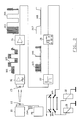
- the device represented in FIG. 1 is an exemplary microwave device usable as a detector for automatic door opening or as an intrusion detector, but not provided with a self-monitoring system.
- a transmitter circuit comprises a Gunn diode 12 placed in a tuned cavity; suitably polarized by a supply circuit 11, the Gunn diode generates a microwave signal which is radiated in space by a horn antenna.
- any object or person moving in front of the detector reflects part of the incident wave; this reflected wave is picked up by the antenna and mixed with the incident wave thanks to a Schottky diode 13 placed in a waveguide located between the cavity and the antenna. Consequently and according to the Doppler effect, a low frequency signal is available at the terminals of the mixing diode 13.
- the frequency of the Doppler signal is proportional to the speed of the obstacle detected and its amplitude is proportional to the size of the object.
- the Doppler signal is presented at the input of an amplification cell 14 whose bandwidth, for example from 5 to 150 Hz, has been determined to correspond to the speeds of the obstacles to be detected.
- Waveform 100 shows a time slice during which a useful Doppler signal appears.
- the Doppler signal passes through a shaping cell 15; there comes out a square signal 101 which corresponds to the input signal 100. This signal is then integrated into a cell 16 and transformed into an increasing signal by stairs 102.
- a comparator 17 makes it possible to assign a binary value (0/1) to an output signal whose waveform is shown at 103.
- the signal 103 controls the output stage 18 actuating the relay 19 whose output contact 190 is connected to the device to be controlled, for example the mechanism of an automatic door.
- the failure of one or more components of the circuit of FIG. 1 causes the operation of the detector to stop without particular signaling and without securing the controlled device.
- the failure of the Gunn 12 or Schottky 13 diode is such that no signal no longer reaches the measurement chain and the output stage remains perpetually inactive, with the consequences mentioned above.
- the failure of the integration circuit 16 prevents the useful signal from reaching the switching level of the comparator 17 so that the output stage also remains inactive.
- a detection device an example of which is described above, must have its arrangement profoundly modified in order to give it the additional self-monitoring function sought.
- the general principle which is the basis of the invention is the generation of control pulses upstream of the circuit and the control of their presence at the end of the circuit. A judicious interconnection of the components is necessary so that the control pulses pass through all the components of the circuit.
- FIG. 2 attached hereto shows a block diagram of an exemplary microwave device usable as a detector for automatic door opening or as an intrusion detector, but incorporating the invention so as to ensure, in addition to its normal function, that of self-monitoring.
- a transmitter circuit comprises a Gunn diode 22 placed in a tuned cavity; suitably polarized by a supply circuit 21, the Gunn diode generates a microwave signal which is radiated in space by a horn antenna.
- an oscillator-modulator cell 25 constitutes a pulsed signal generator connected to modulate the Gunn diode 22 in amplitude. by a square signal at a frequency of 20 kHz for example. Consequently, the signal radiated in space is also modulated and this modulation is picked up by the Schottky diode 23 when the signal has been reflected by the environment or by an obstacle to be detected.
- the signal received is amplified in an amplification and filtering cell 24, the characteristic of which is the variable gain as a function of the frequency: for example 40 dB for the frequency band comprised for example between 5 Hz and 200 Hz and 20 dB for the frequency band between, for example, 200 Hz and 22 kHz; in any case, the gain for the frequency band corresponding to the Doppler frequency (for example 5 to 200 Hz) is always significantly higher than the gain for the frequency band going up to the control frequency or beyond.
- the characteristic of which is the variable gain as a function of the frequency: for example 40 dB for the frequency band comprised for example between 5 Hz and 200 Hz and 20 dB for the frequency band between, for example, 200 Hz and 22 kHz; in any case, the gain for the frequency band corresponding to the Doppler frequency (for example 5 to 200 Hz) is always significantly higher than the gain for the frequency band going up to the control frequency or beyond.
- a low frequency Doppler signal is available at the terminals of the Schottky diode 23 and a signal whose form d is obtained at the output of the amplification and filtering cell 24.
- the wave is shown at 202 and the frequency of which is the same as that of the signal from the receiver 23, that is to say a signal resulting from the superposition of the modulation on the control frequency.
- the characteristic of the amplification and filtering cell 24 is such that the amplification of the Doppler signal is far greater than the amplification of the signal modulated at 20 kHz and that, compared to a reference voltage, the signal modulated at 20 kHz is always of the same sign as the Doppler signal that it affected.
- the output of the amplification and filtering cell 24 is connected to the negative input (-) of a comparator 26 while the positive input (+) of comparator 26 is applied a reference voltage.
- the signal 201 at the negative input of the comparator 26 produces at the output of the comparator a signal 203 having the frequency of the pulsed signal 200.
- comparator 26 is applied to the input of a monostable rocker 27 whose main function is to calibrate the duty cycle of the pulses; the pulses at 20 kHz are transformed into regular pulses as shown by the waveform shown in 205, while the rising edges of the Doppler signal are transformed into short pulses, of the order of 25 microseconds in duration for example, as shown in 206.
- the output signal of the flip-flop 27 is injected into a cell 28 which supplies the output relays.
- the cell 28 comprises for example a field effect transistor 31, of the Mosfet type, controlled by the pulse signal and which modulates the primary of a transformer 32, the secondary of this transformer being connected to a filtering cell 33.
- a signal whose waveform is shown at 205 is transformed at the output of cell 28 into a continuous signal having a first state 207 and having a voltage level sufficient to keep the output relays activated; this state 207 corresponds to the periods when no obstacle is detected, so that the relays remain activated when the detector is at rest.
- a signal whose waveform is shown at 206 is transformed at the output of cell 28 into a continuous signal having a second state 208 and having a practically zero voltage level which does not make it possible to maintain the output relays activated.
- This state 208 corresponds to the obstacle detection periods so that the relays are deactivated upon detection.
- the output relays 29 control a door opening control member or an alarm device for example.
- Other embodiments of the cell 28 are of course possible, the solution described being only one example in no way limiting.
- a redundant circuit at the output relays 29 and their contacts keeps the system operational when an output contact fails. In fact, if one of the group of contacts 30a and 30b remains blocked in a permanent state, the supply of the relays 29 is interrupted, either immediately or after the next detection, thus definitively preventing the activation of the relays.
- the arrangement according to the invention allows the device to self-monitor; Indeed, the proposed arrangement allows the pulses generated upstream to pass through all parts of the circuit, until detection at the end of the line.
- the transformation of the pulses into a sufficient voltage level to activate the output relays is such that, when these pulses disappear, either during a detection, or because of the failure of any component, the output relays are no longer supplied and transmit information by switching. It is obvious that in the absence of supply, the output relays also switch and that the safety being positive, the cut of the connection cable between the output contacts and the controlled member is also detected. Finally, redundancy at the output relays and their contacts makes it possible to reinforce the security of the output stage.
Landscapes
- Engineering & Computer Science (AREA)
- Computer Security & Cryptography (AREA)
- Physics & Mathematics (AREA)
- General Physics & Mathematics (AREA)
- Burglar Alarm Systems (AREA)
Claims (3)
- Vorrichtung zur elektronischen Erfassung umfassend einen Strahlensender (22) in einem Erfassungsfeld, einen pulssignalgeber (25) zur Modulation der vom Strahlensender (22) abgegebenen Strahlungen, einen Empfänger (23), um die von einem im Erfassungsfeld befindlichen Widerstand reflektierten Strahlungen zu empfangen und ein Doppler-Erfassungssignal zu erzeugen, ein Mittel (26) zum Empfang des Erfassungssignals (201, 202) und zur Erzeugung eines ersten Pulssignals (203) mit der Frequenz des Prüfpulssignals (200), wenn kein Widerstand in Bewegung sich in dem Erfassungsfeld befindet, und zur Erzeugung eines zweiten Signals (204) mit der Frequenz des Dopplersignals des Empfängers, wenn ein Widerstand in Bewegung in dem Erfassungsfeld erfaßt wurde, und ein geschaltetes Mittel zum Empfang der genannten ersten und zweiten Pulssignale (203, 204) zur Erzeugung eines Befehlssignals, das einen ersten Zustand (207) als Antwort auf das genannte erste Signal (203) und einen zweiten Zustand (208) als Antwort auf das genannte zweiten Signal (204) aufweist, und mindestens ein Schaltorgan (29), das auf das Befehlssignal antwortet, dadurch gekennzeichnet, daß die Mittel zum Empfang der genannten ersten und zweiten Pulssignale (203, 204) ein monostabiles Kippglied (27) umfassen, gefolgt von einer Filterzelle (28), gebildet aus einem Schalttransistor (31), der ein elektrisches Schaltmittel (32) zum Umformen der oberhalb eines ausreichenden Spannungsniveaus erzeugten Impulse zum Betätigen des Schaltorgans (29) moduliert, sodaß, wenn diese Impulse verschwinden, das obengenannte Schaltorgan nicht mehr gespeist wird und bei der Umschaltung die Information weiterleitet.
- Vorrichtung nach Anspruch 1, dadurch gekennzeichnet, daß das Mittel (26), welches das Erfassungssignal empfängt, aus einem Komparator besteht, mit einem ersten Eingang (-), der geschaltet ist, um das Erfassungssignal zu empfangen und mit einem zweiten Eingang (+), der geschaltet ist, um eine Bezugsspannung zu empfangen.
- Vorrichtung nach Anspruch 1 oder 2, dadurch gekennzeichnet, daß das Signal des Empfängers (23) in einem Verstärker (24) mit einer höheren Verstärkung für das Frequenzband des modulierten Signals (202) als für das Frequenzband des Prüfsignals (201) verstärkt wird.
Priority Applications (2)
| Application Number | Priority Date | Filing Date | Title |
|---|---|---|---|
| EP19890870122 EP0411234B1 (de) | 1989-07-31 | 1989-07-31 | Elektronisches automatisches Überwachungssystem |
| DE1989620873 DE68920873T2 (de) | 1989-07-31 | 1989-07-31 | Elektronisches automatisches Überwachungssystem. |
Applications Claiming Priority (1)
| Application Number | Priority Date | Filing Date | Title |
|---|---|---|---|
| EP19890870122 EP0411234B1 (de) | 1989-07-31 | 1989-07-31 | Elektronisches automatisches Überwachungssystem |
Publications (2)
| Publication Number | Publication Date |
|---|---|
| EP0411234A1 EP0411234A1 (de) | 1991-02-06 |
| EP0411234B1 true EP0411234B1 (de) | 1995-01-25 |
Family
ID=8203284
Family Applications (1)
| Application Number | Title | Priority Date | Filing Date |
|---|---|---|---|
| EP19890870122 Expired - Lifetime EP0411234B1 (de) | 1989-07-31 | 1989-07-31 | Elektronisches automatisches Überwachungssystem |
Country Status (2)
| Country | Link |
|---|---|
| EP (1) | EP0411234B1 (de) |
| DE (1) | DE68920873T2 (de) |
Cited By (2)
| Publication number | Priority date | Publication date | Assignee | Title |
|---|---|---|---|---|
| EP2418505A1 (de) | 2010-07-26 | 2012-02-15 | Bea S.A. | Modulierender Retroreflektor zum Testen eines Dopplertransceivers |
| DE202010018461U1 (de) | 2010-07-26 | 2016-11-08 | Bea Sa | Dopplertransceiver |
Families Citing this family (1)
| Publication number | Priority date | Publication date | Assignee | Title |
|---|---|---|---|---|
| CH696611A5 (de) * | 2001-01-11 | 2007-08-15 | Reglomat Ag | Verfahren zur Selbstüberwachung eines Gerätes zur automatischen Betätigung von Gegenstäden sowie das Gerät. |
Family Cites Families (4)
| Publication number | Priority date | Publication date | Assignee | Title |
|---|---|---|---|---|
| US4035798A (en) * | 1974-03-27 | 1977-07-12 | Pittway Corporation | Ultrasonic intrusion detection system |
| US3932870A (en) * | 1974-05-31 | 1976-01-13 | American District Telegraph Company | On-line test circuit for intrusion alarm systems |
| JPS5910630Y2 (ja) * | 1976-03-19 | 1984-04-03 | ホーチキ株式会社 | 移動物体警報装置 |
| US4660024A (en) * | 1985-12-16 | 1987-04-21 | Detection Systems Inc. | Dual technology intruder detection system |
-
1989
- 1989-07-31 DE DE1989620873 patent/DE68920873T2/de not_active Expired - Fee Related
- 1989-07-31 EP EP19890870122 patent/EP0411234B1/de not_active Expired - Lifetime
Cited By (3)
| Publication number | Priority date | Publication date | Assignee | Title |
|---|---|---|---|---|
| EP2418505A1 (de) | 2010-07-26 | 2012-02-15 | Bea S.A. | Modulierender Retroreflektor zum Testen eines Dopplertransceivers |
| US8886134B2 (en) | 2010-07-26 | 2014-11-11 | Bea Sa | Monitoring system for a doppler transceiver |
| DE202010018461U1 (de) | 2010-07-26 | 2016-11-08 | Bea Sa | Dopplertransceiver |
Also Published As
| Publication number | Publication date |
|---|---|
| EP0411234A1 (de) | 1991-02-06 |
| DE68920873T2 (de) | 1995-08-31 |
| DE68920873D1 (de) | 1995-03-09 |
Similar Documents
| Publication | Publication Date | Title |
|---|---|---|
| US5093656A (en) | Active supervision of motion-detection systems | |
| CH630482A5 (fr) | Installation pour la protection des personnes et des biens dans une agglomeration urbaine. | |
| EP0073776A1 (de) | Elektrische meldevorrichtung mit mindestens einem empfänger und einem sender. | |
| FR2541022A1 (fr) | Appareil de telesignalisation | |
| EP0411234A1 (de) | Elektronisches automatisches Überwachungssystem | |
| EP0681723B1 (de) | Entstoerungsfunkvorrichtung fuer systeme zur ueberwachung des eindringens | |
| EP0044232A1 (de) | Tragbarer digitaler Dosismesser zum Messen und Überwachen einer ionisierenden Strahlung | |
| EP0683913B1 (de) | System zum übermitteln von informationen, insbesondere für personen mit reduzierten sinnesfunktionen | |
| EP2678844B1 (de) | Alarmauslösende vorrichtung für ein sicherheitssystem und verfahren zur installation einer alarmauslösenden vorrichtung | |
| US5043703A (en) | Supervision of autodyne microwave motion-detection system | |
| EP0255812A2 (de) | Überwachungsvorrichtung mit infraroten und radiofrequenten Fühlerkomponenten | |
| EP0312431B1 (de) | Waren- und/oder Personen-Fernüberwachungsverfahren | |
| FR2672410A1 (fr) | Dispositif de surveillance et de protection anti-vol. | |
| EP2963590B1 (de) | Betriebsverfahren eines alarm- und/oder heiminstallationssystems, und entsprechendes alarm-und/oder heiminstallations-system | |
| FR2573893A1 (fr) | Procede et dispositifs pour declencher une alarme ou un automatisme en evitant des declenchements intempestifs | |
| EP1204083B1 (de) | Verfahren und Vorrichtung zur multifrequenzen Überwachung und/oder Meldung | |
| FR2745915A1 (fr) | Dispositif detecteur de brouillard | |
| EP0694893B1 (de) | Alarmdetektionsvorrichtung mit Stromschleifen und Bake zur Lokalisierung von Waterzonen für eine solche Vorrichtung | |
| BE1002349A6 (fr) | Detecteur electronique auto-adaptatif. | |
| FR2812433A1 (fr) | Procede et dispositif pour la protection en continu contre les intrusions dans des locaux eventuellement habites | |
| FR2720178A1 (fr) | Ensemble de protection d'appareils, en particulier contre le vol, sous-ensemble de détection et sous-ensemble de surveillance pour un tel ensemble de protection. | |
| EP2678845B1 (de) | Alarmauslösende vorrichtung für ein sicherheitssystem | |
| FR2647538A1 (fr) | Dispositif de surveillance d'une installation frigorifique | |
| EP3971610A1 (de) | Alarm für kraftfahrzeug | |
| FR2575571A1 (fr) | Installation de securite anti-intrusion |
Legal Events
| Date | Code | Title | Description |
|---|---|---|---|
| PUAI | Public reference made under article 153(3) epc to a published international application that has entered the european phase |
Free format text: ORIGINAL CODE: 0009012 |
|
| AK | Designated contracting states |
Kind code of ref document: A1 Designated state(s): AT BE CH DE ES FR GB GR IT LI LU NL SE |
|
| RBV | Designated contracting states (corrected) |
Designated state(s): BE CH DE FR GB IT LI NL SE |
|
| 17P | Request for examination filed |
Effective date: 19910716 |
|
| 17Q | First examination report despatched |
Effective date: 19930714 |
|
| GRAA | (expected) grant |
Free format text: ORIGINAL CODE: 0009210 |
|
| AK | Designated contracting states |
Kind code of ref document: B1 Designated state(s): BE CH DE FR GB IT LI NL SE |
|
| REF | Corresponds to: |
Ref document number: 68920873 Country of ref document: DE Date of ref document: 19950309 |
|
| ITF | It: translation for a ep patent filed | ||
| GBT | Gb: translation of ep patent filed (gb section 77(6)(a)/1977) |
Effective date: 19950501 |
|
| PLBE | No opposition filed within time limit |
Free format text: ORIGINAL CODE: 0009261 |
|
| STAA | Information on the status of an ep patent application or granted ep patent |
Free format text: STATUS: NO OPPOSITION FILED WITHIN TIME LIMIT |
|
| 26N | No opposition filed | ||
| REG | Reference to a national code |
Ref country code: CH Ref legal event code: PLI Owner name: BELGIAN ELECTRONIC RESEARCH ''B.E.R.'', SOCIETE AN |
|
| REG | Reference to a national code |
Ref country code: GB Ref legal event code: IF02 |
|
| PGFP | Annual fee paid to national office [announced via postgrant information from national office to epo] |
Ref country code: BE Payment date: 20050603 Year of fee payment: 17 |
|
| PGFP | Annual fee paid to national office [announced via postgrant information from national office to epo] |
Ref country code: FR Payment date: 20050606 Year of fee payment: 17 |
|
| PGFP | Annual fee paid to national office [announced via postgrant information from national office to epo] |
Ref country code: NL Payment date: 20050615 Year of fee payment: 17 |
|
| PGFP | Annual fee paid to national office [announced via postgrant information from national office to epo] |
Ref country code: CH Payment date: 20050627 Year of fee payment: 17 |
|
| PGFP | Annual fee paid to national office [announced via postgrant information from national office to epo] |
Ref country code: SE Payment date: 20050714 Year of fee payment: 17 |
|
| PGFP | Annual fee paid to national office [announced via postgrant information from national office to epo] |
Ref country code: GB Payment date: 20050725 Year of fee payment: 17 |
|
| PGFP | Annual fee paid to national office [announced via postgrant information from national office to epo] |
Ref country code: DE Payment date: 20060714 Year of fee payment: 18 |
|
| PG25 | Lapsed in a contracting state [announced via postgrant information from national office to epo] |
Ref country code: LI Free format text: LAPSE BECAUSE OF NON-PAYMENT OF DUE FEES Effective date: 20060731 Ref country code: GB Free format text: LAPSE BECAUSE OF NON-PAYMENT OF DUE FEES Effective date: 20060731 Ref country code: CH Free format text: LAPSE BECAUSE OF NON-PAYMENT OF DUE FEES Effective date: 20060731 Ref country code: BE Free format text: LAPSE BECAUSE OF NON-PAYMENT OF DUE FEES Effective date: 20060731 |
|
| PGFP | Annual fee paid to national office [announced via postgrant information from national office to epo] |
Ref country code: IT Payment date: 20060731 Year of fee payment: 18 |
|
| PG25 | Lapsed in a contracting state [announced via postgrant information from national office to epo] |
Ref country code: SE Free format text: LAPSE BECAUSE OF NON-PAYMENT OF DUE FEES Effective date: 20060801 |
|
| PG25 | Lapsed in a contracting state [announced via postgrant information from national office to epo] |
Ref country code: NL Free format text: LAPSE BECAUSE OF NON-PAYMENT OF DUE FEES Effective date: 20070201 |
|
| REG | Reference to a national code |
Ref country code: CH Ref legal event code: PL |
|
| GBPC | Gb: european patent ceased through non-payment of renewal fee |
Effective date: 20060731 |
|
| NLV4 | Nl: lapsed or anulled due to non-payment of the annual fee |
Effective date: 20070201 |
|
| EUG | Se: european patent has lapsed | ||
| REG | Reference to a national code |
Ref country code: FR Ref legal event code: ST Effective date: 20070330 |
|
| BERE | Be: lapsed |
Owner name: BELGIAN ELECTRONIC RESEARCH *BER S.A. Effective date: 20060731 |
|
| PG25 | Lapsed in a contracting state [announced via postgrant information from national office to epo] |
Ref country code: DE Free format text: LAPSE BECAUSE OF NON-PAYMENT OF DUE FEES Effective date: 20080201 Ref country code: FR Free format text: LAPSE BECAUSE OF NON-PAYMENT OF DUE FEES Effective date: 20060731 |
|
| PG25 | Lapsed in a contracting state [announced via postgrant information from national office to epo] |
Ref country code: IT Free format text: LAPSE BECAUSE OF NON-PAYMENT OF DUE FEES Effective date: 20070731 |