EP0411296B1 - Dispositif d'actionnement d'un véhicule - Google Patents
Dispositif d'actionnement d'un véhicule Download PDFInfo
- Publication number
- EP0411296B1 EP0411296B1 EP90111732A EP90111732A EP0411296B1 EP 0411296 B1 EP0411296 B1 EP 0411296B1 EP 90111732 A EP90111732 A EP 90111732A EP 90111732 A EP90111732 A EP 90111732A EP 0411296 B1 EP0411296 B1 EP 0411296B1
- Authority
- EP
- European Patent Office
- Prior art keywords
- oil
- drive arrangement
- arrangement according
- collecting chamber
- closing member
- Prior art date
- Legal status (The legal status is an assumption and is not a legal conclusion. Google has not performed a legal analysis and makes no representation as to the accuracy of the status listed.)
- Expired - Lifetime
Links
Images

Classifications
-
- F—MECHANICAL ENGINEERING; LIGHTING; HEATING; WEAPONS; BLASTING
- F16—ENGINEERING ELEMENTS AND UNITS; GENERAL MEASURES FOR PRODUCING AND MAINTAINING EFFECTIVE FUNCTIONING OF MACHINES OR INSTALLATIONS; THERMAL INSULATION IN GENERAL
- F16H—GEARING
- F16H57/00—General details of gearing
- F16H57/04—Features relating to lubrication or cooling or heating
- F16H57/042—Guidance of lubricant
- F16H57/0421—Guidance of lubricant on or within the casing, e.g. shields or baffles for collecting lubricant, tubes, pipes, grooves, channels or the like
-
- C—CHEMISTRY; METALLURGY
- C23—COATING METALLIC MATERIAL; COATING MATERIAL WITH METALLIC MATERIAL; CHEMICAL SURFACE TREATMENT; DIFFUSION TREATMENT OF METALLIC MATERIAL; COATING BY VACUUM EVAPORATION, BY SPUTTERING, BY ION IMPLANTATION OR BY CHEMICAL VAPOUR DEPOSITION, IN GENERAL; INHIBITING CORROSION OF METALLIC MATERIAL OR INCRUSTATION IN GENERAL
- C23C—COATING METALLIC MATERIAL; COATING MATERIAL WITH METALLIC MATERIAL; SURFACE TREATMENT OF METALLIC MATERIAL BY DIFFUSION INTO THE SURFACE, BY CHEMICAL CONVERSION OR SUBSTITUTION; COATING BY VACUUM EVAPORATION, BY SPUTTERING, BY ION IMPLANTATION OR BY CHEMICAL VAPOUR DEPOSITION, IN GENERAL
- C23C22/00—Chemical surface treatment of metallic material by reaction of the surface with a reactive liquid, leaving reaction products of surface material in the coating, e.g. conversion coatings, passivation of metals
- C23C22/05—Chemical surface treatment of metallic material by reaction of the surface with a reactive liquid, leaving reaction products of surface material in the coating, e.g. conversion coatings, passivation of metals using aqueous solutions
- C23C22/06—Chemical surface treatment of metallic material by reaction of the surface with a reactive liquid, leaving reaction products of surface material in the coating, e.g. conversion coatings, passivation of metals using aqueous solutions using aqueous acidic solutions with pH less than 6
- C23C22/07—Chemical surface treatment of metallic material by reaction of the surface with a reactive liquid, leaving reaction products of surface material in the coating, e.g. conversion coatings, passivation of metals using aqueous solutions using aqueous acidic solutions with pH less than 6 containing phosphates
- C23C22/08—Orthophosphates
- C23C22/12—Orthophosphates containing zinc cations
- C23C22/16—Orthophosphates containing zinc cations containing also peroxy-compounds
-
- C—CHEMISTRY; METALLURGY
- C23—COATING METALLIC MATERIAL; COATING MATERIAL WITH METALLIC MATERIAL; CHEMICAL SURFACE TREATMENT; DIFFUSION TREATMENT OF METALLIC MATERIAL; COATING BY VACUUM EVAPORATION, BY SPUTTERING, BY ION IMPLANTATION OR BY CHEMICAL VAPOUR DEPOSITION, IN GENERAL; INHIBITING CORROSION OF METALLIC MATERIAL OR INCRUSTATION IN GENERAL
- C23C—COATING METALLIC MATERIAL; COATING MATERIAL WITH METALLIC MATERIAL; SURFACE TREATMENT OF METALLIC MATERIAL BY DIFFUSION INTO THE SURFACE, BY CHEMICAL CONVERSION OR SUBSTITUTION; COATING BY VACUUM EVAPORATION, BY SPUTTERING, BY ION IMPLANTATION OR BY CHEMICAL VAPOUR DEPOSITION, IN GENERAL
- C23C22/00—Chemical surface treatment of metallic material by reaction of the surface with a reactive liquid, leaving reaction products of surface material in the coating, e.g. conversion coatings, passivation of metals
- C23C22/05—Chemical surface treatment of metallic material by reaction of the surface with a reactive liquid, leaving reaction products of surface material in the coating, e.g. conversion coatings, passivation of metals using aqueous solutions
- C23C22/06—Chemical surface treatment of metallic material by reaction of the surface with a reactive liquid, leaving reaction products of surface material in the coating, e.g. conversion coatings, passivation of metals using aqueous solutions using aqueous acidic solutions with pH less than 6
- C23C22/07—Chemical surface treatment of metallic material by reaction of the surface with a reactive liquid, leaving reaction products of surface material in the coating, e.g. conversion coatings, passivation of metals using aqueous solutions using aqueous acidic solutions with pH less than 6 containing phosphates
- C23C22/08—Orthophosphates
- C23C22/18—Orthophosphates containing manganese cations
-
- C—CHEMISTRY; METALLURGY
- C23—COATING METALLIC MATERIAL; COATING MATERIAL WITH METALLIC MATERIAL; CHEMICAL SURFACE TREATMENT; DIFFUSION TREATMENT OF METALLIC MATERIAL; COATING BY VACUUM EVAPORATION, BY SPUTTERING, BY ION IMPLANTATION OR BY CHEMICAL VAPOUR DEPOSITION, IN GENERAL; INHIBITING CORROSION OF METALLIC MATERIAL OR INCRUSTATION IN GENERAL
- C23C—COATING METALLIC MATERIAL; COATING MATERIAL WITH METALLIC MATERIAL; SURFACE TREATMENT OF METALLIC MATERIAL BY DIFFUSION INTO THE SURFACE, BY CHEMICAL CONVERSION OR SUBSTITUTION; COATING BY VACUUM EVAPORATION, BY SPUTTERING, BY ION IMPLANTATION OR BY CHEMICAL VAPOUR DEPOSITION, IN GENERAL
- C23C22/00—Chemical surface treatment of metallic material by reaction of the surface with a reactive liquid, leaving reaction products of surface material in the coating, e.g. conversion coatings, passivation of metals
- C23C22/05—Chemical surface treatment of metallic material by reaction of the surface with a reactive liquid, leaving reaction products of surface material in the coating, e.g. conversion coatings, passivation of metals using aqueous solutions
- C23C22/06—Chemical surface treatment of metallic material by reaction of the surface with a reactive liquid, leaving reaction products of surface material in the coating, e.g. conversion coatings, passivation of metals using aqueous solutions using aqueous acidic solutions with pH less than 6
- C23C22/34—Chemical surface treatment of metallic material by reaction of the surface with a reactive liquid, leaving reaction products of surface material in the coating, e.g. conversion coatings, passivation of metals using aqueous solutions using aqueous acidic solutions with pH less than 6 containing fluorides or complex fluorides
- C23C22/36—Chemical surface treatment of metallic material by reaction of the surface with a reactive liquid, leaving reaction products of surface material in the coating, e.g. conversion coatings, passivation of metals using aqueous solutions using aqueous acidic solutions with pH less than 6 containing fluorides or complex fluorides containing also phosphates
-
- C—CHEMISTRY; METALLURGY
- C23—COATING METALLIC MATERIAL; COATING MATERIAL WITH METALLIC MATERIAL; CHEMICAL SURFACE TREATMENT; DIFFUSION TREATMENT OF METALLIC MATERIAL; COATING BY VACUUM EVAPORATION, BY SPUTTERING, BY ION IMPLANTATION OR BY CHEMICAL VAPOUR DEPOSITION, IN GENERAL; INHIBITING CORROSION OF METALLIC MATERIAL OR INCRUSTATION IN GENERAL
- C23C—COATING METALLIC MATERIAL; COATING MATERIAL WITH METALLIC MATERIAL; SURFACE TREATMENT OF METALLIC MATERIAL BY DIFFUSION INTO THE SURFACE, BY CHEMICAL CONVERSION OR SUBSTITUTION; COATING BY VACUUM EVAPORATION, BY SPUTTERING, BY ION IMPLANTATION OR BY CHEMICAL VAPOUR DEPOSITION, IN GENERAL
- C23C22/00—Chemical surface treatment of metallic material by reaction of the surface with a reactive liquid, leaving reaction products of surface material in the coating, e.g. conversion coatings, passivation of metals
- C23C22/73—Chemical surface treatment of metallic material by reaction of the surface with a reactive liquid, leaving reaction products of surface material in the coating, e.g. conversion coatings, passivation of metals characterised by the process
- C23C22/77—Controlling or regulating of the coating process
-
- F—MECHANICAL ENGINEERING; LIGHTING; HEATING; WEAPONS; BLASTING
- F01—MACHINES OR ENGINES IN GENERAL; ENGINE PLANTS IN GENERAL; STEAM ENGINES
- F01M—LUBRICATING OF MACHINES OR ENGINES IN GENERAL; LUBRICATING INTERNAL COMBUSTION ENGINES; CRANKCASE VENTILATING
- F01M1/00—Pressure lubrication
- F01M1/12—Closed-circuit lubricating systems not provided for in groups F01M1/02 - F01M1/10
-
- F—MECHANICAL ENGINEERING; LIGHTING; HEATING; WEAPONS; BLASTING
- F01—MACHINES OR ENGINES IN GENERAL; ENGINE PLANTS IN GENERAL; STEAM ENGINES
- F01M—LUBRICATING OF MACHINES OR ENGINES IN GENERAL; LUBRICATING INTERNAL COMBUSTION ENGINES; CRANKCASE VENTILATING
- F01M11/00—Component parts, details or accessories, not provided for in, or of interest apart from, groups F01M1/00 - F01M9/00
- F01M11/06—Means for keeping lubricant level constant or for accommodating movement or position of machines or engines
-
- F—MECHANICAL ENGINEERING; LIGHTING; HEATING; WEAPONS; BLASTING
- F01—MACHINES OR ENGINES IN GENERAL; ENGINE PLANTS IN GENERAL; STEAM ENGINES
- F01M—LUBRICATING OF MACHINES OR ENGINES IN GENERAL; LUBRICATING INTERNAL COMBUSTION ENGINES; CRANKCASE VENTILATING
- F01M11/00—Component parts, details or accessories, not provided for in, or of interest apart from, groups F01M1/00 - F01M9/00
- F01M11/0004—Oilsumps
- F01M2011/0037—Oilsumps with different oil compartments
- F01M2011/0041—Oilsumps with different oil compartments for accommodating movement or position of engines
Definitions
- the invention relates to a drive device of a vehicle with features according to the preamble of claim 1.
- the invention is based on a drive device known from US Pat. No. 4,677,948.
- An oil pan is arranged on the underside of the engine block, from which oil can be extracted via a suction line by means of a servo pump and can be fed to a circuit.
- rotating bodies - including balancer shafts - reach down into the area of the oil pan to below the maximum opening level, which are at least partially covered by an organ that protects them against splashing oil - a housing.
- provisions are made for collecting and extracting oil that has penetrated into the interior of the protective housing, but here are based on the construction of the shafts and their function. This solution cannot be used for other cases, i.e. other rotating bodies.
- Such, from the crankshaft of the engine rotating bodies are to be understood as those such as gears, sprockets, flywheels or the like, which reach down into the area of the oil pan to below the maximum opening level and without suitable protective measures from during driving operation within the oil pan splashing oil back and forth.
- This uncontrolled splashing or sloshing oil represents an uncontrolled resistance to the running of the rotating body, so that its operation can in some cases be considerably impaired.
- the latter would be the case, for example, in connection with a flywheel, which is part of a braking energy recovery device as an energy store.
- a flywheel should be able to rotate as freely and freely as possible and should not be exposed to energy-consuming resistors. With such a flywheel, however, even if it is stored in its own housing, there would be the danger that oil, for example, would accumulate in the housing through bearings or from other sources and, if too large, could hinder the running of the flywheel.
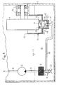
- the drive device of a vehicle e.g. Passenger cars, trucks, omnibuses, tractors, bulldozers, forklifts, tracked vehicles or the like are essentially only shown in the part which is formed by the oil pan 1 arranged on the underside of the engine / transmission block.
- oil can be pumped into a circuit by means of a servo pump 2 via a suction line 3 with a check valve 4 opening in the suction direction and a subsequent filter 5 (not essential and not necessary at this point), which in the drawing is only through a delivery line 6 is indicated.
- This circuit can be a cooling oil circuit, the control and / or working circuit of hydraulic machines as part of a hydrostatic-mechanical power split transmission, a brake circuit or the power steering of the vehicle.
- At least one rotary body 7 extends as part of the drive device, such as a toothed wheel, sprocket, flywheel or the like, down to the area of the oil pan 1, to the extent that it has its lowermost edge 8 below that marked with 9 maximum oil pan filling level.
- Rotating body 7 Under normal circumstances, the rotating body 7 would be thrown with oil during the travel of the vehicle as a result of the constantly sloshing or splashing oil filling 10, which would impede its proper running, but at least could lead to a loss in efficiency.
- These disadvantages are remedied by the fact that Rotating body 7 an organ 11 which seals it off from the oil filling 10 of the oil pan 1 and, by at least partially covering its lower region, protects against oil splashing or sloshing around while driving and also measures for collecting and suctioning into the interior of the protective Organ 11 are assigned to penetrated oil.
- This protective element 11 can be designed in the manner of a protective shell which is open at the top and covers only the lower region of the rotating body 7 or the rotating body 7. This embodiment can be seen from Figures 1 to 3.
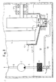
- the protective element 11 can, however, also be formed by a housing which completely surrounds the rotating body 7 but is not hermetically sealed, which case can be seen from FIG. Not hermetically sealed means that over time oil, albeit in small amounts, for example from the bearings 13 of the rotating body 7 or from the oil pan 1 via said bearing 13 or via connection points between housing parts, for example by capillary action, into the interior of the housing Protection organ 11 can penetrate.
- the housing forming the protective member 11 is held in a fixed association with respect to the oil pan 1 by means not described in detail - see FIG. 4.
- the protective element 11 is formed by a protective shell, it is arranged within the oil pan 1 or, if prefabricated as an independent component, is fastened in the oil pan 1 in such a way that its upper edge 12 is a larger piece above the maximum oil pan Level 9 is.
- the dimension between the upper edge 12 of the protective shell 11 and the maximum oil pan filling level 9 differs from case to case, to be determined by experiments and then to be determined that at least a large spill of the oil 10 stored in the oil pan 1 into the interior of the protective shell 11 can be avoided even under extreme driving conditions.
- Oil which has nevertheless penetrated into the interior of the protective member 11 runs downward on its inner wall surface and is collected in a collecting space 14 which is formed according to the invention at the lowest or deep area of the protective member 11.
- the latter is preferably formed by a cup-shaped bulge with an annular cylindrical side wall 15 and a flat or funnel-shaped bottom 16.
- a float valve 19 can, for example, be provided as a means for closing or opening the collecting space outlet 17 as required.
- Its float 20 is formed by a relatively thick, round plate which is guided with a relatively large radial clearance in the circular-cylindrical collecting space 14. Said radial play must be at least so large that the oil which has penetrated into the interior of the protective member 11 can freely penetrate into the collecting space 14 and there into the area below the float 20.
- the outlet 17 of the collecting space 14 is normally closed by the float valve 19 when the ball head 22 causes it to open due to its own weight the valve seat 23 is seated and not enough oil has been collected in the collecting space 14. However, the outlet 17 is opened when a sufficiently large amount of oil is collected in the collecting space 14 and the float valve 19 is lifted off its valve seat 23 as a result of the buoyancy force caused thereby.
- the oil collected can be extracted by means of the servo pump 2, specifically via the suction line 18, which in the exemplary embodiments shown leads to the suction line 3 and opens into the latter in the area between the check valve 4 and the filter 5. It is important to ensure that the outlet 17 of the collecting space 14 or the junction of the suction line 18 in the suction line 3 of the servo pump 2 is level higher than the inlet area 24 of the suction line 3 and the weight of the closing element or the closing spring of the check valve acting thereon 4 is designed so that there is a pressure drop in the oil conveyed by the servo pump 2 from the oil pan 1 through the suction line 3, which enables this oil suction from the collecting space 14.
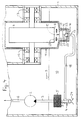
- a sensor that detects the opening and closing of the float valve 19 is provided, which in the event that the servo pump 2 should be inactive at the moment the float valve 19 is opened, triggers the servo pump 2 to be started up and, if necessary, switched off again after the float valve 19 has been closed .
- This sensor can be arranged at a suitable point in the collecting space 14 or the protective element 11.
- the sensor simultaneously forms a stop 25 which limits the opening stroke of the float valve 19 and which extends into the protective element 11 is installed above the collecting space 14 between this and the lower edge 8 of the rotating body 7.
- the stop / sensor 15 can be formed, for example, by a metallic plate which forms part of a capacitive proximity switch and is connected via an electrical signal line to a control device regulating the operation of the servo pump 2.
Landscapes
- Chemical & Material Sciences (AREA)
- Engineering & Computer Science (AREA)
- Mechanical Engineering (AREA)
- General Chemical & Material Sciences (AREA)
- Chemical Kinetics & Catalysis (AREA)
- Materials Engineering (AREA)
- Metallurgy (AREA)
- Organic Chemistry (AREA)
- General Engineering & Computer Science (AREA)
- Lubrication Details And Ventilation Of Internal Combustion Engines (AREA)
Claims (10)
Applications Claiming Priority (2)
| Application Number | Priority Date | Filing Date | Title |
|---|---|---|---|
| DE3925411A DE3925411A1 (de) | 1989-08-01 | 1989-08-01 | Antriebseinrichtung eines fahrzeuges |
| DE3925411 | 1989-08-01 |
Publications (2)
| Publication Number | Publication Date |
|---|---|
| EP0411296A1 EP0411296A1 (fr) | 1991-02-06 |
| EP0411296B1 true EP0411296B1 (fr) | 1992-09-02 |
Family
ID=6386270
Family Applications (1)
| Application Number | Title | Priority Date | Filing Date |
|---|---|---|---|
| EP90111732A Expired - Lifetime EP0411296B1 (fr) | 1989-08-01 | 1990-06-21 | Dispositif d'actionnement d'un véhicule |
Country Status (2)
| Country | Link |
|---|---|
| EP (1) | EP0411296B1 (fr) |
| DE (2) | DE3925411A1 (fr) |
Families Citing this family (9)
| Publication number | Priority date | Publication date | Assignee | Title |
|---|---|---|---|---|
| DE10017271A1 (de) * | 2000-04-06 | 2001-10-11 | Zahnradfabrik Friedrichshafen | Vorrichtung zur Reduzierung des Luftanteils im Öl eines Automatgetriebes |
| DE102004060595C5 (de) * | 2004-12-09 | 2013-12-19 | Getrag Getriebe- Und Zahnradfabrik Hermann Hagenmeyer Gmbh & Cie Kg | Doppelkupplungsanordnung |
| JP5202596B2 (ja) | 2010-09-15 | 2013-06-05 | 太平洋工業株式会社 | オイルパン内槽弁構造 |
| DE102011079824A1 (de) * | 2011-07-26 | 2013-01-31 | Zf Friedrichshafen Ag | Vorrichtung zur Kontrolle und Einstellung eines Ölstandes |
| DE102011080710A1 (de) * | 2011-08-10 | 2013-02-14 | Zf Friedrichshafen Ag | Getriebe eines Kraftfahrzeuges mit Hybridantrieb |
| DE102014013580A1 (de) * | 2014-09-13 | 2016-03-17 | Daimler Ag | Kraftfahrzeuggetriebevorrichtung |
| DE102019218418A1 (de) * | 2019-11-28 | 2021-06-02 | Zf Friedrichshafen Ag | Getriebe für ein Kraftfahrzeug |
| US11920671B1 (en) * | 2022-09-13 | 2024-03-05 | Dana Italia S.R.L. | Lubrication system with a flow regulating floater container |
| DE102022212783B3 (de) | 2022-11-29 | 2023-12-28 | Magna powertrain gmbh & co kg | Schmier- und Kühlsystem und Verfahren zum Betreiben eines Schmier- und Kühlsystems mit Notlaufschmierung eines elektrischen Antriebs |
Family Cites Families (14)
| Publication number | Priority date | Publication date | Assignee | Title |
|---|---|---|---|---|
| DE403609C (de) * | 1924-10-04 | Kemna Fa J | Brennstoffbehaelteranordnung fuer Kraftfahrzeuge | |
| FR502791A (fr) * | 1916-03-30 | 1920-05-26 | Louis Renault | Perfectionnements aux systèmes de graissage des moteurs |
| BE398581A (fr) * | 1932-10-17 | |||
| FR856123A (fr) * | 1938-06-14 | 1940-05-30 | Daimler Benz Ag | Circulation d'huile de lubrification pour moteurs à combustion interne |
| US2525946A (en) * | 1945-12-13 | 1950-10-17 | Albert O Roberts | Power reclaimer |
| US3106263A (en) * | 1961-07-11 | 1963-10-08 | Gen Motors Corp | Engine with side reservoir oil pan |
| US3214989A (en) * | 1963-04-01 | 1965-11-02 | Falk Corp | Vertical right angle speed reducer |
| DE1908240A1 (de) * | 1969-02-19 | 1970-08-27 | Klaue Hermann | Trockensumpfschmiersystem,insbesondere fuer luftgekuehlte Kraftwagenmotoren |
| DE1948186A1 (de) * | 1969-09-24 | 1971-04-01 | Daimler Benz Ag | Kolbenbrennkraftmaschine |
| DE2701939A1 (de) * | 1977-01-19 | 1978-07-20 | Kloeckner Humboldt Deutz Ag | Schmiervorrichtung fuer brennkraftmaschinen zur sicheren oelversorgung bei schraeglagen |
| US4519348A (en) * | 1983-04-21 | 1985-05-28 | Edward Hamilton | Oil pan and windage tray for high performance engines |
| DE3334044C2 (de) * | 1983-09-21 | 1985-11-07 | Audi AG, 8070 Ingolstadt | Hubkolben-Brennkraftmaschine |
| US4677948A (en) * | 1986-05-29 | 1987-07-07 | Chrysler Motors Corporation | Lubricating system for an engine balancing device |
| DE3619296A1 (de) * | 1986-06-07 | 1987-12-10 | Porsche Ag | Vorrichtung zum selbsttaetigen nachfuellen eines fluessigkeitsbehaelters |
-
1989
- 1989-08-01 DE DE3925411A patent/DE3925411A1/de not_active Withdrawn
-
1990
- 1990-06-21 DE DE9090111732T patent/DE59000287D1/de not_active Expired - Lifetime
- 1990-06-21 EP EP90111732A patent/EP0411296B1/fr not_active Expired - Lifetime
Also Published As
| Publication number | Publication date |
|---|---|
| DE59000287D1 (de) | 1992-10-08 |
| EP0411296A1 (fr) | 1991-02-06 |
| DE3925411A1 (de) | 1991-02-07 |
Similar Documents
| Publication | Publication Date | Title |
|---|---|---|
| DE10034561B4 (de) | Vorrichtung zum Steuern der Menge an Zahnradschmiermittel in Abhängigkeit von der Drehzahl | |
| EP1697660B1 (fr) | Boite de vitesse pour vehicule | |
| WO2020157004A1 (fr) | Ensemble d'engrenage | |
| EP0411296B1 (fr) | Dispositif d'actionnement d'un véhicule | |
| CH675758A5 (fr) | ||
| DE3906330A1 (de) | Oelreservoiranordnung fuer ein automatik-getriebe | |
| WO2020120022A1 (fr) | Ensemble siège réglable de motocycle et motocycle | |
| DE4010738C2 (fr) | ||
| DE102012004279A1 (de) | Achsgetriebe für ein Kraftfahrzeug | |
| DE10014368A1 (de) | Ölauffangvorrichtung und Ölpumpe für eine Brennkraftmaschine | |
| DE19833536C2 (de) | Vorrichtung zum Entlüften eines Getriebes | |
| DE10238237A1 (de) | Kammerentleerungseinrichtung | |
| DE3630973C2 (fr) | ||
| DE2946293C2 (de) | Schmiervorrichtung für einen in einem Getriebegehäuse untergebrachten Getriebezug | |
| DE1238270B (de) | Vorrichtung zur selbsttaetigen Steuerung der Ansaugleitung einer Schmieroelpumpe von Brennkraftmaschinen | |
| DE4001467C2 (fr) | ||
| DE102019211854A1 (de) | Ölversorgungssystem für ein Automatikgetriebe | |
| DE10213506A1 (de) | ABS-Stellglied mit Ablassanschlussleitung | |
| DE2103161A1 (de) | Hydrostatischer Antrieb mit Dualkraftquelle | |
| DE102004045441B4 (de) | Vorrichtung zur Versorgung eines Antriebs mit flüssigem Schmiermittel | |
| DE102018114255B4 (de) | Antriebseinheit mit schaltbarem Getriebe und Hydraulikmodul | |
| DE3209804A1 (de) | Kreiselverdichter mit schieberartig in radialer richtung verstellbaren fluegeln | |
| EP4279767A1 (fr) | Transmission pourvue de réservoir de récupération d'huile | |
| DE2148868A1 (de) | Hydraulisches Steuersystem zur Steuerung der Standhoehe von Fluessigkeit in einem Tank | |
| DE102022200991A1 (de) | Fahrzeuggetriebe |
Legal Events
| Date | Code | Title | Description |
|---|---|---|---|
| PUAI | Public reference made under article 153(3) epc to a published international application that has entered the european phase |
Free format text: ORIGINAL CODE: 0009012 |
|
| AK | Designated contracting states |
Kind code of ref document: A1 Designated state(s): DE FR GB IT SE |
|
| 17P | Request for examination filed |
Effective date: 19910223 |
|
| 17Q | First examination report despatched |
Effective date: 19910910 |
|
| ITF | It: translation for a ep patent filed | ||
| GRAA | (expected) grant |
Free format text: ORIGINAL CODE: 0009210 |
|
| AK | Designated contracting states |
Kind code of ref document: B1 Designated state(s): DE FR GB IT SE |
|
| REF | Corresponds to: |
Ref document number: 59000287 Country of ref document: DE Date of ref document: 19921008 |
|
| ET | Fr: translation filed | ||
| GBT | Gb: translation of ep patent filed (gb section 77(6)(a)/1977) | ||
| PLBE | No opposition filed within time limit |
Free format text: ORIGINAL CODE: 0009261 |
|
| STAA | Information on the status of an ep patent application or granted ep patent |
Free format text: STATUS: NO OPPOSITION FILED WITHIN TIME LIMIT |
|
| 26N | No opposition filed | ||
| PGFP | Annual fee paid to national office [announced via postgrant information from national office to epo] |
Ref country code: SE Payment date: 19940609 Year of fee payment: 5 |
|
| PGFP | Annual fee paid to national office [announced via postgrant information from national office to epo] |
Ref country code: GB Payment date: 19940613 Year of fee payment: 5 |
|
| PGFP | Annual fee paid to national office [announced via postgrant information from national office to epo] |
Ref country code: DE Payment date: 19940616 Year of fee payment: 5 |
|
| PGFP | Annual fee paid to national office [announced via postgrant information from national office to epo] |
Ref country code: FR Payment date: 19940630 Year of fee payment: 5 |
|
| EAL | Se: european patent in force in sweden |
Ref document number: 90111732.5 |
|
| PG25 | Lapsed in a contracting state [announced via postgrant information from national office to epo] |
Ref country code: GB Effective date: 19950621 |
|
| PG25 | Lapsed in a contracting state [announced via postgrant information from national office to epo] |
Ref country code: SE Effective date: 19950622 |
|
| GBPC | Gb: european patent ceased through non-payment of renewal fee |
Effective date: 19950621 |
|
| PG25 | Lapsed in a contracting state [announced via postgrant information from national office to epo] |
Ref country code: FR Effective date: 19960229 |
|
| PG25 | Lapsed in a contracting state [announced via postgrant information from national office to epo] |
Ref country code: DE Effective date: 19960301 |
|
| EUG | Se: european patent has lapsed |
Ref document number: 90111732.5 |
|
| REG | Reference to a national code |
Ref country code: FR Ref legal event code: ST |
|
| PG25 | Lapsed in a contracting state [announced via postgrant information from national office to epo] |
Ref country code: IT Free format text: LAPSE BECAUSE OF NON-PAYMENT OF DUE FEES Effective date: 20050621 |