EP0411431A2 - Windschutzscheiben-Waschanlagenpumpe für Fahrzeuge - Google Patents
Windschutzscheiben-Waschanlagenpumpe für Fahrzeuge Download PDFInfo
- Publication number
- EP0411431A2 EP0411431A2 EP90114113A EP90114113A EP0411431A2 EP 0411431 A2 EP0411431 A2 EP 0411431A2 EP 90114113 A EP90114113 A EP 90114113A EP 90114113 A EP90114113 A EP 90114113A EP 0411431 A2 EP0411431 A2 EP 0411431A2
- Authority
- EP
- European Patent Office
- Prior art keywords
- washer fluid
- washer
- pressurized
- pump
- valve
- Prior art date
- Legal status (The legal status is an assumption and is not a legal conclusion. Google has not performed a legal analysis and makes no representation as to the accuracy of the status listed.)
- Granted
Links
Images



Classifications
-
- B—PERFORMING OPERATIONS; TRANSPORTING
- B60—VEHICLES IN GENERAL
- B60S—SERVICING, CLEANING, REPAIRING, SUPPORTING, LIFTING, OR MANOEUVRING OF VEHICLES, NOT OTHERWISE PROVIDED FOR
- B60S1/00—Cleaning of vehicles
- B60S1/02—Cleaning windscreens, windows or optical devices
- B60S1/46—Cleaning windscreens, windows or optical devices using liquid; Windscreen washers
- B60S1/48—Liquid supply therefor
- B60S1/481—Liquid supply therefor the operation of at least part of the liquid supply being controlled by electric means
-
- F—MECHANICAL ENGINEERING; LIGHTING; HEATING; WEAPONS; BLASTING
- F04—POSITIVE - DISPLACEMENT MACHINES FOR LIQUIDS; PUMPS FOR LIQUIDS OR ELASTIC FLUIDS
- F04D—NON-POSITIVE-DISPLACEMENT PUMPS
- F04D15/00—Control, e.g. regulation, of pumps, pumping installations or systems
- F04D15/0005—Control, e.g. regulation, of pumps, pumping installations or systems by using valves
- F04D15/0016—Control, e.g. regulation, of pumps, pumping installations or systems by using valves mixing-reversing- or deviation valves
-
- F—MECHANICAL ENGINEERING; LIGHTING; HEATING; WEAPONS; BLASTING
- F04—POSITIVE - DISPLACEMENT MACHINES FOR LIQUIDS; PUMPS FOR LIQUIDS OR ELASTIC FLUIDS
- F04D—NON-POSITIVE-DISPLACEMENT PUMPS
- F04D5/00—Pumps with circumferential or transverse flow
- F04D5/002—Regenerative pumps
Definitions
- the present invention relates to a windscreen washer pump, and particularly to a washer pump for use with a vehicle, which serves to supply washer fluid to two systems for the windscreen.
- two washer pumps having different delivery pressure are mounted on a conventional vehicle and the washer fluid is supplied to the front and rear glasses with different delivery pressure by using the respective washer pumps.
- the delivery pressure of the washer pump when the delivery pressure of the washer pump is set to a higher value in relation to the front glass, the delivery pressure of the washer fluid to the rear glass is so high that a reduction in efficiency takes place due to the spray of the fluid or the like.
- the delivery pressure of the washer pump when the delivery pressure of the washer pump is set to a lower value in relation to the rear glass, a substantial quantity of washer fluid cannot be supplied to the front glass.
- the wind pressure is high as in the case where the vehicle is running at high speed, the landing point of the washer fluid onto the front glass varies correspondingly and hence the wiping ability of the front glass is deteriorated.
- the washer pump according to the present invention comprises a pressurized mechanism which can pressurize the washer fluid from a washer fluid supply source so as to deliver the same therefrom and also can change the delivery of the washer fluid in two directions, a first valve operative to be opened according to the delivery of the washer fluid from the pressurized mechanism in one direction for introducing the pressurized washer fluid onto a first window glass, a second valve operative to be opened according to the delivery of the washer fluid from the pressurized mechanism in the other direction for introducing the pressurized washer fluid onto a second window glass, and bypass means serving to take out part of the washer fluid delivered in the one direction for reducing the delivery rate of the washer fluid to the first window glass below that of the washer fluid to the second window glass.
- the delivery rate of the washer fluid from the pressurized mechanism in the one direction can be reduced as compared to that of the washer fluid therefrom in the other direction in spite of there being a single pump.
- the bypass means can be applied to both cases, one for where it is mounted on the pressurized mechanism and the other for where it is provided between the pressurized mechanism and each of the washer fluid injection nozzles.
- the pressurized mechanism is provided with a pressurized flow passage formed by a pump chamber and an impeller, the pressurized washer fluid is taken out from a portion closer to an outlet for discharging the washer fluid onto the first window glass rather than an outlet for discharging the washer fluid onto the second window glass.
- the bypass means is provided at the portion other than the pressurized mechanism, part of the pressurized washer fluid is taken out from a guide passage formed between the pressurized mechanism and an injection nozzle provided adjacent to the first window glass.
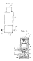
- FIG. 2 illustrates the complete exterior of a washer pump for a vehicle, to which a first embodiment of the present invention is applied.
- FIG. 3 depicts a sectional schematic illustration taken along line 3 - 3 of FIG. 2.
- the washer pump according to the first embodiment is provided with a cylinder 13 projected from the outer peripheral wall of a housing 10 formed in a substantially cylindrical fashion and having an intake hole, i.e., an inlet 12 formed therein and connected to an unillustrated washer fluid supply tank.
- the washer pump is also provided with a first cylindrical outlet 14 communicating with a nozzle disposed at a rear glass of the vehicle and a second cylindrical outlet 16 communicating with a nozzle disposed at a front glass, at the outer peripheral wall adjacent to the lower part of the housing 10.
- a rotor of a motor 18 is contained in the upper part of the housing 10, while a pump chamber 24 accommodating an impeller 22 is formed in the lower part thereof.
- a rotary shaft 20 of the rotor 18 is attached to the central portion of the impeller 22.
- Washer fluid which is to be supplied to the pump via the inlet 12, is fed to the side of the rear glass from the first outlet 14 at a given delivery pressure by allowing the motor 18 to drive the impeller 22 in the forward direction, whereas the washer fluid is supplied to the side of a front glass from the second outlet at a given delivery pressure by driving the impeller 22 in the reverse direction.
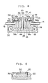
- FIG. 4 shows a schematic cross-sectional view of the lower part of the washer pump shown in FIG. 3, especially the pump chamber 24.
- the pump chamber 24 is formed between the housing 10 and a cap 26 by fitting the cap 26 onto the bottom of the housing 10 thus defining an upper half portion of the pump chamber 24 in a state where the impeller 22 is accommodated.
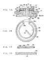
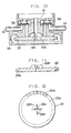
- FIG. 1 shows an exploded view of the pump chamber portion depicted in FIG. 4.
- FIG. 1(A) is a cross-sectional view of a housing bottom portion formed with the upper half portion of the pump chamber 24.
- FIG. 1(B) is a bottom view of the bottom face 28 of the pump chamber 24 shown in FIG. 1(A).
- FIG. 1(C) is a cross-sectional view of the impeller and
- FIG. 1(D) is a cross-sectional view of the cap 26.
- a flow channel 30 through which washer fluid flows along the outer periphery of the pump chamber 24 is formed in a ring form within the pump chamber 24.
- the flow channel 30 employed in the present embodiment includes a ring-shaped concave groove 32 formed in the vicinity of the outer periphery of the bottom face 28 of the pump chamber 24 and a ring-shaped concave groove 34 formed in the top face of the cap 26 opposed to the concave groove 32.
- the impeller 22 employed in the present embodiment is formed with a half-moon aperture 22c with an aperture, which is brought into engagement with the rotary shaft 20 of the motor 18 in the central portion of a disc 22a, and grooves 22b defined at regular intervals along the outer periphery of the impeller 22.
- the grooves 22b are formed to be rotated and driven along the flow channel 23 of the pump chamber 24.
- the interval between the impeller 22 and both side walls of the pump chamber 24, i.e., between the bottom face 28 of the housing 10 and the top face of the cap 26 is very narrow.
- first valve chamber 36 and second valve chamber 38 are located between the inlet 12 and the pump chamber 24.
- the first valve chamber 36 is formed with a communication hole 36a communicating with the inlet 12 at the upper part thereof.
- a communication hole 36b communicates with the first outlet 14 at the lower part thereof and a communication hole 36c communicates with one end side of the flow channel 30, all of which are perforated in parallel to the rotary shaft 20 of the motor 18.
- valves 40, 42 which are always biased downwards by means of compression coil springs 39 and designed to block the communication holes 36b, 38b from communicating with the first and second outlets 14, 16.
- Each of the cut-away portions 45 is partly formed at the peripheral edge of the aperture of each of the communication holes 36c, 38c communicating with the valve chambers 36, 38 in a direction in which the area of the aperture is enlarged. As shown in FIGS. 1 and 4, each of the cut-away portions 45 is disposed such that they partially uncover the valves 40, 42 even when the communication holes 36c, 38c are blocked by the valves 40, 42.
- both ends of the flow channel 30 are in a communicating state with the inlet 12 through the first and second valve chambers 36, 38.
- both ends of the flow channel 30 communicate with the first and second outlets 14, 16 via the first and second valves chambers 36, 38.
- an insertion hole 44 for the rotary shaft 20 has a diameter larger than that of the rotary shaft 20 of the motor 18 and is formed to extend toward the central portion of the pump chamber 24 from the inlet 12. The distal end of the rotary shaft 20 is attached to the impeller 22 through the insertion hole 44.
- a groove is formed onto the bottom face 28 of the housing 10 in a radial direction of the pump chamber 24 from the insertion hole 44 to provide a bypass flow passage 50.
- the bypass flow passage 50 reaches a concave groove 32 and hence the washer fluid within the flow channel 30 can not return to the inlet 12 through the bypass flow passage 50 and the insertion hole 44.
- the washer fluid flows into the one end of the flow channel 30 from the inlet 12 via either one of the first or second valve chambers 36, 38.
- the washer fluid is selectively expelled from the first outlet 14 or second outlet 16 through either one of the valve chambers 36, 38 which communicate with the other end side of the flow channel 30.
- the washer fluid flows into the one end side of the flow channel 30 from the inlet 12 via the second valve chamber 38.
- the washer fluid then flows into the flow channel 30 while gradually raising the pressure in the washer fluid by means of Westco groove 22b formed in the outer periphery of the impeller 22, and then proceeds to the first valve chamber 36.
- the delivery pressure of the washer fluid has sufficiently been raised.
- the valve 40 is forced upwards so as to block the communication hole 36a and the washer fluid is expelled from the first outlet 14 at high pressure under the state as referred to above. At this time, no washer fluid is expelled from the second outlet 16 because the communication hole 38b is blocked by the valve 42 within another valve chamber 38.
- the washer fluid from the inlet 12 is expelled at a sufficiently high delivery pressure from the second outlet 16 via the first valve chamber 36, the flow channel 30 and the second valve chamber 38.
- the pressurized washer fluid within the flow channel 30 is returned to the inlet 12 through the bypass flow passage 50 and the insertion hole 44 for the rotary shaft 20.
- the level of the delivery pressure at the first outlet 14 and the second outlet 16 can be set as needed depending on which portion of the flow channel 30 the bypass flow passage 50 is provided.
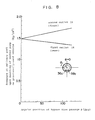
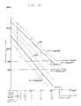
- FIG. 8 shows observed data of positions of the bypass flow passage vs. pressure at the outlet of the flow passage in the case where the washer pump according to the present embodiment is mounted on a practically-used vehicle.
- the first and second outlets 14, 16 are connected to the rear and front sides thereof respectively.
- the difference between the pressure exerted on the washer fluid delivered from the first outlet 14 and that exerted on the washer fluid delivered from the second outlet 16 can arbitrarily be set depending on the position where the bypass flow passage 50 is located.
- the washer fluid can be supplied to the front glass at full delivery pressure by means of a single washer pump, whereas the washer fluid can be supplied to the rear glass at an appropriate lower delivery pressure.
- the present invention can also bring about an advantageous effect in that any pressure remaining inside the piping arrangement can be released owing to the provision of the bypass flow passage 50 within the pump chamber 24.
- the washer fluid within the piping flows into the first valve chamber 36 from the first outlet 14 owing to residual pressure in the piping and the valve 40 is forced upwards by that residual pressure, so that the washer fluid flows into the flow channel 30 of the pump chamber 24.
- the washer fluid is then introduced into the second valve chamber 38 from the flow channel 30 and hence the valve 42 is forced upwards by this residual pressure, so that the washer fluid is expelled from the second outlet 16 to the front glass, thereby causing a problem.
- a bypass passage 50 for introducing the washer fluid which flows into the flow channel 30 into the inlet 12 via the bypass flow passage 50 and the insertion hole 44 for the rotary shaft 20 is formed by providing the bypass flow passage 50 at the flow channel 30.
- bypass flow passage 50 is defined in the form of a straight line by way of an illustrative example in the present embodiment.
- the present invention is however not necessarily limited to this embodiment.
- the bypass flow passage 50 may be inclined with respect to the radial direction of the flow channel 30 or may be defined in the form of a curve as shown in FIG. 9.
- the difference in the fluid delivery rate between the bypass flow passage 50 and the flow channel 30 can be made greater depending on the flow direction of the bypassed washer fluid which flows within the flow channel 30.
- the washer fluid can be extruded from the first outlet 14 in a state of the delivery pressure being fully reduced.
- the washer fluid can be expelled from the second out let 16 by the delivery pressure borne essentially by the pump itself. It is therefore possible to make use of the performance of the pump itself more effectively.
- FIGS. 10 through 12 show a preferred second embodiment of a washer pump according to the present invention.
- the features of the present embodiment reside in that a plurality of supplemental vanes 22d are centrally provided on the surface of the impeller 22 in radial form and by-passed washer fluid, which is introduced via the bypass flow passage 50, is forced under pressure into the inlet 12 through the insertion hole 44 so as to be effectively discharged from the impeller 22.
- supplemental vanes 22d are provided symmetrically with respect to the center of the rotary shaft 20. They may be defined in an arbitrary form and the number of the vanes 22d may be increased or decreased as needed.
- a means for forcibly pressure feeding washer fluid taken from the bypass flow passage 50 to the inlet 12 is used as an alternative to the supplemental vanes, their shapes are not necessarily limited to the vanes.
- FIG. 13 shows a third embodiment according to the present invention, which corresponds to a modification of the bypass flow passage.
- a pair of cut-away portions 56 are formed in a cylindrical valve seat 54 which is brought into contact with the valve 40 in the first valve chamber 36.
- the cut-away portions 56 are formed in an opposing relationship to each other respectively with the central axis of the valve seat 54 interposed therebetween.
- the delivery pressure of the first outlet 14 can be arbitrarily set depending on to what degree the delivery rate of the by-passed washer fluid refluxed to the side of the inlet 12 via the cut-away portions 56 is established.
- FIG. 14 depicts observed data of the aperture area vs. the fluid delivery rate in the case where the washer pump according to the present embodiment is actually mounted on a vehicle and the first and second outlets 14, 16 are connected to the rear and front sides thereof respectively.
- the observed data shows how the delivery rate of the washer fluid supplied to the rear side from the first outlet 14 is reduced as the sectional area of the cut-away portions 56 indicated by the abscissa axis in the drawing is gradually increased provided that the delivery pressure of the pump chamber 24 is constant.
- Observed data indicated by numeral 100 in the same drawing shows where the first outlet 14 is coupled to orifices each of which has a diameter of 0.8 mm. This data also shows that the groove sectional area is 4 mm2 in order to adjust the delivery pressure to 1.1 kg/cm2 (140 cc/10 sec. in the case of the fluid delivery rate).
- Observed data indicated by numeral 200 in the same drawing shows where the first outlet 14 is connected to an orifice which has the diameter of 1.0 mm and also indicates that the sectional area is about 2.8 mm2 with a view toward adjusting the delivery pressure to 1.65 kg/cm2 (100 cc/10 sec. in the case of the fluid delivery rate).
- the second valve chamber 38 employed in the present embodiment is so formed that the communication hole 38a thereof is completely blocked with the valve 42.
- the present embodiment is similar to the aforementioned embodiment in that any pressure which remains within the piping can be released by providing, as a bypass flow passage, each of the cut-away portions 56 within the first valve chamber 36.
- cut-away portions 56 are formed onto the valve seat 54 for the purpose of the bypass in the present embodiment. However, cut-away portions are formed at a portion where the valve 40 is brought into contact with the valve seat 54 so as to communicate with the communication hole 36a, whereby they may be used for the purpose of the bypass.
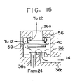
- a bypass window 58 communicating with the inlet 12, which is other than the cut-away portions 56 may be provided as needed as shown in FIG. 15 by way of example.
- the delivery rate of the by-passed washer fluid, which flows toward the first outlet 14 can be made greater and at the same time, the delivery pressure of the washer fluid from the first outlet 14 can be rendered lower.
- bypass window 58 may be formed as the bypass flow passage as needed in the present invention.
Landscapes
- Engineering & Computer Science (AREA)
- Mechanical Engineering (AREA)
- General Engineering & Computer Science (AREA)
- Water Supply & Treatment (AREA)
- Structures Of Non-Positive Displacement Pumps (AREA)
Applications Claiming Priority (4)
| Application Number | Priority Date | Filing Date | Title |
|---|---|---|---|
| JP1989090035U JPH0749037Y2 (ja) | 1989-07-31 | 1989-07-31 | 車両用ウォッシャポンプ |
| JP1198518A JP2665259B2 (ja) | 1989-07-31 | 1989-07-31 | 車両用ウォッシャポンプ |
| JP198518/89 | 1989-07-31 | ||
| JP90035/89 | 1989-07-31 |
Publications (3)
| Publication Number | Publication Date |
|---|---|
| EP0411431A2 true EP0411431A2 (de) | 1991-02-06 |
| EP0411431A3 EP0411431A3 (en) | 1991-08-14 |
| EP0411431B1 EP0411431B1 (de) | 1994-11-02 |
Family
ID=26431553
Family Applications (1)
| Application Number | Title | Priority Date | Filing Date |
|---|---|---|---|
| EP90114113A Expired - Lifetime EP0411431B1 (de) | 1989-07-31 | 1990-07-24 | Windschutzscheiben-Waschanlagenpumpe für Fahrzeuge |
Country Status (3)
| Country | Link |
|---|---|
| US (1) | US5071315A (de) |
| EP (1) | EP0411431B1 (de) |
| DE (1) | DE69013788T2 (de) |
Cited By (6)
| Publication number | Priority date | Publication date | Assignee | Title |
|---|---|---|---|---|
| FR2703409A1 (fr) * | 1993-04-02 | 1994-10-07 | Seim Ind | Pompe centrifuge bi-directionnelle. |
| EP0411428B1 (de) * | 1989-07-31 | 1995-01-11 | Asmo Co., Ltd. | Windschutzscheiben-Waschpumpe für ein Fahrzeug |
| EP1167774A3 (de) * | 2000-06-29 | 2002-06-26 | Mitsuba Corporation | Pumpenmotor für ein Fahrzeug |
| EP1201932A3 (de) * | 2000-10-24 | 2003-10-22 | Siemens Aktiengesellschaft | Fördereinrichtung |
| WO2004012968A1 (de) * | 2002-07-31 | 2004-02-12 | Valeo Wischersysteme Gmbh | Steuerventil, düsenanordnung und waschanlage |
| FR3139085A1 (fr) * | 2022-08-31 | 2024-03-01 | Valeo Systèmes D’Essuyage | Procédé de gestion d’un dispositif de nettoyage d’un capteur pour véhicule |
Families Citing this family (7)
| Publication number | Priority date | Publication date | Assignee | Title |
|---|---|---|---|---|
| KR100217618B1 (ko) * | 1996-12-12 | 1999-09-01 | 정몽규 | 와셔액 분사위치 조절 장치 |
| FR2824365A1 (fr) | 2001-05-04 | 2002-11-08 | Stein Seal Compagny | Systeme d'etancheite pour systemes fermes a haute pression contenant un element rotatif et un logement |
| US6675989B1 (en) | 2001-06-28 | 2004-01-13 | Valeo Electrical Systems, Inc. | Windshield washer pump with integrated fluid level sensor |
| US6530758B1 (en) * | 2001-06-28 | 2003-03-11 | Valeo Electrical Systems, Inc. | Composite fluid control membrane for windshield washer pump and method of manufacturing same |
| JP5543608B2 (ja) * | 2010-10-05 | 2014-07-09 | 株式会社ニフコ | 流体分配バルブ並びにこれを備えた流体供給システム及びその制御方法 |
| US20130177451A1 (en) * | 2012-01-11 | 2013-07-11 | Continental Automotive Systems, Inc. | Washer system and pump for same |
| US20210309187A1 (en) * | 2020-04-02 | 2021-10-07 | Uatc, Llc | Vehicle Sensor Cleaning Systems |
Family Cites Families (11)
| Publication number | Priority date | Publication date | Assignee | Title |
|---|---|---|---|---|
| US926748A (en) * | 1909-04-19 | 1909-07-06 | Frank D Kelly | Rotary engine. |
| GB997863A (en) * | 1962-07-24 | 1965-07-07 | B S A Harford Pumps Ltd | Improvements relating to centrifugal pumps |
| FR2377911A1 (fr) * | 1977-01-24 | 1978-08-18 | Seim | Circuit d'alimentation de gicleurs et vehicule equipe d'un tel circuit |
| US4284386A (en) * | 1979-04-27 | 1981-08-18 | Hudson James L | High pressure pump |
| DE3317155C1 (de) * | 1983-05-11 | 1984-09-06 | Ford-Werke AG, 5000 Köln | Scheibenwaschanlage eines Fahrzeuges |
| JPS60212668A (ja) * | 1984-04-05 | 1985-10-24 | Nippon Denso Co Ltd | モ−タ式燃料ポンプ |
| IT1179626B (it) * | 1984-04-30 | 1987-09-16 | Mes Sa | Girante a geometria variabile per pompe centrifughe a due mandate selezionabili mediante inversione del senso di rotazione particolarmente per impianti lavacristalli di autoveicoli |
| IT206424Z2 (it) * | 1985-08-01 | 1987-08-10 | Mes Sa | Pompa a doppia mandata per impianti di bordo di autoveicoli incorporante mezzi valvolari di non ritorno impedenti lo svuotamento delle tubazioni di impianto |
| DE3708327A1 (de) * | 1987-03-14 | 1988-09-22 | Bosch Gmbh Robert | Einrichtung zum foerdern von fluessigkeit auf zwei ueber spritzduesen zu netzende, mit abstand voneinander angeordnete scheibenbereiche eines kraftfahrzeugs |
| US4900235A (en) * | 1988-03-07 | 1990-02-13 | Mccord Winn Textron Inc. | Reversible pump assembly |
| JPH01176792U (de) * | 1988-06-03 | 1989-12-18 |
-
1990
- 1990-07-24 DE DE69013788T patent/DE69013788T2/de not_active Expired - Fee Related
- 1990-07-24 EP EP90114113A patent/EP0411431B1/de not_active Expired - Lifetime
- 1990-07-26 US US07/558,294 patent/US5071315A/en not_active Expired - Lifetime
Cited By (9)
| Publication number | Priority date | Publication date | Assignee | Title |
|---|---|---|---|---|
| EP0411428B1 (de) * | 1989-07-31 | 1995-01-11 | Asmo Co., Ltd. | Windschutzscheiben-Waschpumpe für ein Fahrzeug |
| FR2703409A1 (fr) * | 1993-04-02 | 1994-10-07 | Seim Ind | Pompe centrifuge bi-directionnelle. |
| EP1167774A3 (de) * | 2000-06-29 | 2002-06-26 | Mitsuba Corporation | Pumpenmotor für ein Fahrzeug |
| EP1201932A3 (de) * | 2000-10-24 | 2003-10-22 | Siemens Aktiengesellschaft | Fördereinrichtung |
| EP1469203A3 (de) * | 2000-10-24 | 2004-12-08 | Siemens Aktiengesellschaft | Förderpumpe |
| WO2004012968A1 (de) * | 2002-07-31 | 2004-02-12 | Valeo Wischersysteme Gmbh | Steuerventil, düsenanordnung und waschanlage |
| CN100377937C (zh) * | 2002-07-31 | 2008-04-02 | 瓦莱奥擦拭系统有限公司 | 控制阀、喷嘴装置和清洗设备 |
| FR3139085A1 (fr) * | 2022-08-31 | 2024-03-01 | Valeo Systèmes D’Essuyage | Procédé de gestion d’un dispositif de nettoyage d’un capteur pour véhicule |
| WO2024046652A1 (fr) * | 2022-08-31 | 2024-03-07 | Valeo Systèmes d'Essuyage | Procédé de gestion d'un dispositif de nettoyage d'un capteur pour vehicule |
Also Published As
| Publication number | Publication date |
|---|---|
| EP0411431B1 (de) | 1994-11-02 |
| DE69013788T2 (de) | 1995-03-09 |
| DE69013788D1 (de) | 1994-12-08 |
| US5071315A (en) | 1991-12-10 |
| EP0411431A3 (en) | 1991-08-14 |
Similar Documents
| Publication | Publication Date | Title |
|---|---|---|
| EP0411431A2 (de) | Windschutzscheiben-Waschanlagenpumpe für Fahrzeuge | |
| GB2278888A (en) | A fuel pump with curved vapour channel | |
| US5578221A (en) | Fuel filter with improved hand primer | |
| EP0411428B1 (de) | Windschutzscheiben-Waschpumpe für ein Fahrzeug | |
| JP2525062Y2 (ja) | ウオッシャポンプ | |
| EP0536159A1 (de) | Aggregat zum fördern von kraftstoff vom vorratstank zur brennkraftmaschine eines kraftfahrzeuges. | |
| US5344293A (en) | Double diaphragm leakproof sealing device for electric windscreen washer pumps | |
| US4919591A (en) | Washer pump for automobiles | |
| US7048523B2 (en) | Proportioning pump including integral orifice | |
| EP0609820A1 (de) | Flügelzellenpumpe | |
| EP0779433B1 (de) | Elektrische Brennstoffpumpe für Kraftfahrzeug | |
| US4259042A (en) | Confectionary pumps | |
| US5289681A (en) | Power steering system | |
| JPH0749037Y2 (ja) | 車両用ウォッシャポンプ | |
| JP2665259B2 (ja) | 車両用ウォッシャポンプ | |
| JPS62195488A (ja) | 車両用燃料供給装置 | |
| KR20210036034A (ko) | 차량용 워셔펌프 | |
| JPS6243341A (ja) | ウオツシヤ液噴出装置 | |
| RU2194168C2 (ru) | Система смазки двигателя внутреннего сгорания | |
| US5961308A (en) | Cylindrical pump device having a flexible blade member | |
| KR100324116B1 (ko) | 멀티분배장치 | |
| JPH086647Y2 (ja) | ウオツシヤ液供給装置 | |
| KR19980047446U (ko) | 자동차용 윈드와셔 구조 | |
| WO1991003646A1 (de) | Flügelzellenkompressor | |
| JPH01121596A (ja) | 円周流型ポンプ |
Legal Events
| Date | Code | Title | Description |
|---|---|---|---|
| PUAI | Public reference made under article 153(3) epc to a published international application that has entered the european phase |
Free format text: ORIGINAL CODE: 0009012 |
|
| AK | Designated contracting states |
Kind code of ref document: A2 Designated state(s): DE GB |
|
| PUAL | Search report despatched |
Free format text: ORIGINAL CODE: 0009013 |
|
| AK | Designated contracting states |
Kind code of ref document: A3 Designated state(s): DE GB |
|
| 17P | Request for examination filed |
Effective date: 19920115 |
|
| 17Q | First examination report despatched |
Effective date: 19930824 |
|
| GRAA | (expected) grant |
Free format text: ORIGINAL CODE: 0009210 |
|
| AK | Designated contracting states |
Kind code of ref document: B1 Designated state(s): DE GB |
|
| REF | Corresponds to: |
Ref document number: 69013788 Country of ref document: DE Date of ref document: 19941208 |
|
| PLBE | No opposition filed within time limit |
Free format text: ORIGINAL CODE: 0009261 |
|
| STAA | Information on the status of an ep patent application or granted ep patent |
Free format text: STATUS: NO OPPOSITION FILED WITHIN TIME LIMIT |
|
| 26N | No opposition filed | ||
| REG | Reference to a national code |
Ref country code: GB Ref legal event code: IF02 |
|
| PGFP | Annual fee paid to national office [announced via postgrant information from national office to epo] |
Ref country code: DE Payment date: 20080807 Year of fee payment: 19 |
|
| PGFP | Annual fee paid to national office [announced via postgrant information from national office to epo] |
Ref country code: GB Payment date: 20080806 Year of fee payment: 19 |
|
| GBPC | Gb: european patent ceased through non-payment of renewal fee |
Effective date: 20090724 |
|
| PG25 | Lapsed in a contracting state [announced via postgrant information from national office to epo] |
Ref country code: GB Free format text: LAPSE BECAUSE OF NON-PAYMENT OF DUE FEES Effective date: 20090724 |
|
| PG25 | Lapsed in a contracting state [announced via postgrant information from national office to epo] |
Ref country code: DE Free format text: LAPSE BECAUSE OF NON-PAYMENT OF DUE FEES Effective date: 20100202 |