EP0411470A1 - Werkzeugheft - Google Patents
Werkzeugheft Download PDFInfo
- Publication number
- EP0411470A1 EP0411470A1 EP90114310A EP90114310A EP0411470A1 EP 0411470 A1 EP0411470 A1 EP 0411470A1 EP 90114310 A EP90114310 A EP 90114310A EP 90114310 A EP90114310 A EP 90114310A EP 0411470 A1 EP0411470 A1 EP 0411470A1
- Authority
- EP
- European Patent Office
- Prior art keywords
- booklet
- tool
- approximately
- width
- blade
- Prior art date
- Legal status (The legal status is an assumption and is not a legal conclusion. Google has not performed a legal analysis and makes no representation as to the accuracy of the status listed.)
- Granted
Links
Images

Classifications
-
- B—PERFORMING OPERATIONS; TRANSPORTING
- B25—HAND TOOLS; PORTABLE POWER-DRIVEN TOOLS; MANIPULATORS
- B25G—HANDLES FOR HAND IMPLEMENTS
- B25G1/00—Handle constructions
- B25G1/10—Handle constructions characterised by material or shape
- B25G1/105—Handle constructions characterised by material or shape for screwdrivers, wrenches or spanners
Definitions
- the invention relates to a tool book for chisels, carpenter chisels or the like.
- Two types of tool handles are known for chisels.
- the oldest type is a wooden booklet with a circular cross-section.
- flat flats are then applied, which run parallel to one another and to the cutting edge.
- a circumferential flat bead is formed in the region of the end facing the blade.
- the second known type of chisel booklet consists of plastic and has an approximately oval cross-section, the thickness and width of the booklet not changing almost over its entire length. Only shortly before the blade-side end is a finger recess arranged, which runs all around and can be used to hold the thumb.
- Chisels are used in three types of activities.
- the chisel is normally held with the left hand so that the thumb is in the area of the head end of the booklet.
- the right hand is used to hit the head of the chisel with a hammer.
- the left hand is used to hold the chisel, to align and guide it in all three directions.
- the longitudinal axis of the chisel is transverse to the forearm axis, and the cutting edge of the chisel is parallel to the forearm axis.
- the handle In the second type of handling, namely cutting, the handle is held upside down, so that the thumb lies in the area of the blade-side end of the handle.
- the longitudinal axis of the chisel is oriented approximately as an extension of the forearm axis.
- the chisel must be held at an angle.
- the chisel is rotated 90 ° around its longitudinal axis. In this position, the user can better control the position of the cutting edge.
- the third way of handling is to pry off a loosened chip, whether by chipping or by hitting. This can be done with both the right and the left hand in both hand positions mentioned. Here it goes less about orienting the chisel than about applying greater leverage.
- the position of the hand to the handle differs in all three types of handling. Due to the different types of posture, shapes for other tools cannot provide any inspiration for a chisel booklet.
- the invention has for its object to improve a chisel booklet in terms of cheaper handling and less fatigue of the user's hand.
- the invention proposes a tool book according to the main claim.
- the fingers of the leading hand lie in the recesses of the fingers on one narrow side surface. Because of the oval cross-section, the hand can precisely steer and guide the chisel. Levering is also possible in this hand position.
- the broad side surface rests on the inside of the thumb and the ball of the thumb, and the fingertips can lie in the finger depressions, but in different finger depressions than in the striking position.
- the invention thus creates a form of the booklet which, despite different possibilities for holding the booklet, means an ergonomic improvement in all three types of hand position.
- the thickness and width of the booklet decrease more in the direction of the blade-side end of the booklet than in the direction of the opposite head end of the booklet.
- the little finger has a shorter length and therefore the handle on the striking posture Point has a smaller cross section than on the opposite index finger.
- the handling of the booklet is also improved in the chip holding, in which the little finger lies in the area of the larger cross section of the booklet. This is due to the fact that the booklet is held at an angle in this position.
- the location of the greatest thickness and width of the booklet is in the top half of the booklet, preferably at about a third to a quarter of the booklet length.
- the collar forms a rounded contact surface for the thumb.
- the thumb rests on this contact surface in the chip holding, and usually on the broad side surface.
- the collar forms a rounded contact surface on the opposite side for the index finger, which in the chip holding is here, for example, transverse to the longitudinal axis of the booklet.
- the finger depressions are essentially arranged only in the narrow side faces, while the broad side faces do without such finger depressions and are in particular of a smooth design. This results in a wide and smooth contact surface for chip holding.
- the booklet has a stepped head.
- the head therefore has a reduced cross section, which is surrounded by a step in the booklet on all sides.
- the little finger can rest in the chip position.
- the booklet consists of plastic, in particular is injection molded in one piece from plastic.
- the invention proposes to give the booklet a total length of 12 cm, whereby the length can also be reduced to approximately 11.5 cm for smaller handles.
- the greatest width of the booklet is in a range between 32 and 38 mm, while the greatest thickness is in a range of 28 - 34 mm. These dimensions are larger than known in the prior art.
- the handle for a chisel shown in the figures has an elongated shape with a cross-section which is approximately oval, see FIG. 3.
- the cross-section can be seen schematically in FIG Has length as width.
- the length of the cross section corresponds to the width of the booklet, while the width of the cross section corresponds to the thickness of the booklet.
- the handle is thus delimited by two narrow side surfaces 11 lying opposite one another and two broad side surfaces 12 running approximately at right angles to these.
- the handle is attached to a chisel blade.
- the booklet has a stepped head 15.
- the head 15 has a somewhat smaller cross section than the immediately adjacent area of the booklet, so that here a step 16 is formed which extends all around the booklet.
- the narrow side surfaces seen from the side in FIG. 1 are provided with finger depressions 17, each of which is about 2 to 3 mm deep and are intended to rest the finger limbs.
- the last finger grip recess 17 facing the wood chisel blade lies directly adjacent to a collar 18 delimiting the handle toward the blade.
- This collar 18 merges via a curved transition 19 into the location 20 with the smallest cross section of the handle.
- the thickness of the booklet continuously increases from this point 20 to a point 21 of the largest cross-section at which both the width and the thickness of the tool booklet have their maximum size. This point 21 with the largest cross section divides the length of the booklet approximately in the range of one third to two thirds and is arranged in the top half of the tool booklet.
- the tool handle is mirror-symmetrical with respect to its two longitudinal center planes.
- the broad side surfaces 12 are smooth, that is, without finger depressions.
- the finger depressions 17 are only present in the narrow side surfaces 11.
- the left hand engages the handle in a right-handed person so that the thumb side of the hand is at the top in the illustration in FIG. 1 and the finger limbs come to rest in the depressions 17 of a narrow side surface.
- the axis of the forearm runs perpendicular to the longitudinal axis of the tool, and the longitudinal axis of the cross section, which lies in the paper plane in FIG. 1, extends in the extension of the forearm. This longitudinal axis of the cross section naturally also runs parallel to the cutting edge of the chisel.
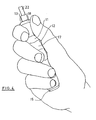
- the hand engages the tool in such a way that the little finger lies in the area of the head 15 of the booklet, while the thumb and palm rest on a broad side surface 12 and the thumb lies against the rounded transition 19 of the collar 18 lies. This is attempted to be shown in FIG. 4.
- the tool is used upside down.
- the shaft 22 thus protrudes from the thumb side of the hand.
- the tool is also rotated by 90 ° about its longitudinal axis, so that the finger members, see left in FIG. 4, no longer act on the narrow side surface 11 of the booklet that has the finger recesses 17, but instead lies on the smooth broad side surface 12 the opposite broad side surface 12 on the ball of the thumb.
- the thumb also lies on the broad side surface 12 in the extension of the ball of the thumb.
- the tool booklet is set at an angle so that it is oriented approximately in the extension of the forearm. The fingertips rest on the narrow side surface 11 and can either engage in the finger grip recesses 17 or rest on the elevations formed between them.
Landscapes
- Engineering & Computer Science (AREA)
- Mechanical Engineering (AREA)
- Knives (AREA)
- Pistons, Piston Rings, And Cylinders (AREA)
- Cutting Tools, Boring Holders, And Turrets (AREA)
- Scissors And Nippers (AREA)
- Diaphragms For Electromechanical Transducers (AREA)
- Stored Programmes (AREA)
- Eye Examination Apparatus (AREA)
Abstract
Description
- Die Erfindung betrifft ein Werkzeugheft für Stechbeitel, Zimmermannsbeitel o. dgl.
- Bei Stechbeiteln sind zwei Arten von Werkzeugheften bekannt. Die älteste Art ist ein aus Holz bestehendes Heft, das einen kreisrunden Querschnitt aufweist. Im Bereich zweier gegenüberliegender Längsseiten sind dann ebene Abflachungen angebracht, die parallel zueinander und zu der Schneidkante verlaufen. Im Bereich des der Klinge zugewandten Endes ist ein umlaufender flacher Wulst ausgebildet.
- Die zweite bekannte Art von Stechbeitelheften besteht aus Kunststoff und weist einen etwa ovalen Querschnitt auf, wobei sich Dicke und Breite des Hefts fast über dessen gesamte Länge nicht ändern. Erst kurz vor dem klingenseitigen Ende ist eine Fingermulde angeordnet, die ringsum läuft und zur Aufnahme des Daumens dienen kann.
- In jüngerer Zeit wurde ein aus Kunststoff bestehendes Heft vorgeschlagen, das ebenfalls einen ovalen Querschnitt aufweist und dessen Abmessungen sich in Richtung auf die Klinge verringern. Der Übergang zur Klinge erfolgt glatt, so daß hier keine Anlagefläche gebildet ist. Beim Stoßen mit diesem Stechbeitel soll der ausgestreckte Zeigerfinger an einer Verbreiterung der Klinge anliegen. Das Heft ist mit einer Querverrippung versehen.
- Bei vielen Werkzeugarten ist bislang versucht worden, die Form des Griffes unter ergonomischen Gesichtspunkten der Hand des Benutzers anzupassen. Dies ist bei den bisherigen Bemühungen deswegen möglich, weil bei vielen Werkzeugarten die Hand in nur einer Stellung am Werkzeug angreift. Bei Stechbeiteln ist dies jedoch nicht der Fall.
- Stechbeitel werden in dreierlei Arten von Tätigkeiten verwendet. Bei der ersten wird der Stechbeitel im Normalfall mit der linken Hand so gehalten, daß der Daumen im Bereich des kopfseitigen Endes des Heftes liegt. Mit der rechten Hand wird mit dem Hammer auf den Kopf des Stechbeitels geschlagen. Die linke Hand dient dazu, den Stechbeitel zu halten, in allen drei Richtungen auszurichten und zu führen. Dabei liegt die Längsachse des Stechbeitels quer zur Unterarmachse, und die Schneidkante des Beitels parallel zur Unterarmachse.
- Bei der zweiten Art der Handhabung, nämlich dem Spanen, wird das Heft gerade umgekehrt gehalten, so daß der Daumen im Bereich des klingenseitigen Endes des Griffs liegt. Da bei dieser Haltung aber der Benutzer den Stechbeitel in seiner Längsrichtung schiebt, wird die Längsachse des Stechbeitels etwa in Verlängerung der Unterarmachse orientiert. Zu diesem Zweck muß der Stechbeitel schräg angefaßt werden. Gleichzeitig erfolgt noch eine Drehung des Stechbeitels um 90. um seine Längsachse. In dieser Haltung kann der Benutzer die Lage der Schneidkante besser steuern.
- Die dritte Handhabungsart besteht darin, einen gelösten Span, sei dies durch Abspanen oder durch Schlagen geschehen, abzuhebeln. Dies kann sowohl mit der rechten als auch mit der linken Hand in beiden genannten Handstellungen geschehen. Hierbei geht es weniger um eine Orientierung des Stechbeitels als um das Aufbringen größerer Hebelkräfte.
- In allen drei Handhabungsarten ist die Lage der Hand zum Griff unterschiedlich.
Aufgrund der unterschiedlichen Haltungsarten können Formen bei anderen Werkzeugen keine Anregung für ein Stechbeitelheft geben.
Der Erfindung liegt die Aufgabe zugrunde, ein Stechbeitelheft im Hinblick auf eine günstigere Handhabung und geringere Ermüdung der Hand des Benutzers zu verbessern. - Zur Lösung dieser Aufgabe schlägt die Erfindung ein Werkzeugheft nach dem Hauptanspruch vor.
- Bei der Schlaghaltung liegen die Fingerglieder der führenden Hand in den Fingermulden der einen Schmalseitenfläche Aufgrund des ovalen Querschnitts kann die Hand den Stechbeitel genau lenken und führen. Auch ein Hebeln in dieser Handstellung möglich.
- Greift die Hand dagegen zum Spanen um, so liegt die Breitseitenfläche an der Innenseite des Daumens und dem Handballen an, und die Fingerspitzen können in den Fingermulden liegen, jedoch in anderen Fingermulden als bei der Schlaghaltung.
- Die Erfindung schafft also eine Form des Heftes, die trotz unterschiedlicher Möglichkeiten, das Heft zu halten, in allen drei Arten der Handstellung eine ergonomische Verbesserung bedeutet.
- In Weiterbildung der Erfindung kann vorgesehen sein, daß die Dicke und Breite des Heftes sich in Richtung auf das klingenseitige Ende des Hefts stärker verringern als in Richtung auf das gegenüberliegende Kopfende des Hefts. Auf diese Weise wird der Tatsache Rechnung getragen, daß der kleine Finger eine geringere Länge aufweist und daher in der Schlaghaltung das Heft an dieser Stelle einen kleineren Querschnitt aufweist als am gegenüberliegenden Zeigefinger. Überraschenderweise wird dennoch die Handhabung des Heftes auch in der Spanhaltung verbessert, in der der kleine Finger im Bereich des größeren Querschnitts des Heftes liegt. Dies ergibt sich aufgrund der Tatsache, daß das Heft in dieser Haltung schräg gehalten wird.
- In Weiterbildung kann vorgesehen sein, daß die Stelle der größten Dicke und Breite des Hefts in der kopfseitigen Hälfte des Hefts liegt, vorzugsweise bei etwa einem Drittel bis einem Viertel der Heftlänge.
- In Weiterbildung der Erfindung kann vorgesehen sein, daß der Kragen eine abgerundete Anlagefläche für den Daumen bildet. An dieser Anlagefläche liegt der Daumen in der Spanhaltung an, und zwar im Normalfall auf der Breitseitenfläche.
- Es kann in Weiterbildung auch vorgesehen sein, daß der Kragen eine abgerundete Anlagefläche auf der gegenüberliegenden Seite für den Zeigefinger bildet, der in der Spanhaltung hier beispielsweise quer zur Längsachse des Hefts liegt.
- Die Fingermulden sind nach der Erfindung im wesentlichen nur in den Schmalseitenflächen angeordnet, während die Breitseitenflächen ohne derartige Fingermulden auskommen und insbesondere glatt ausgebildet sind. Es ergibt sich somit für die Spanhaltung hier eine breite und glatte Anlagefläche.
- In Weiterbildung der Erfindung kann vorgesehen sein, daß das Heft einen abgesetzten Kopf aufweist. Der Kopf weist also einen verringerten Querschnitt auf, der allseits von einer Stufe umgeben in das Heft übergeht. Hier kann in der Spanhaltung der kleine Finger anliegen.
- Erfindungsgemäß kann vorgesehen sein, daß das Heft aus Kunststoff besteht, insbesondere einstückig aus Kunststoff gespritzt ist.
- Die Erfindung schlägt vor, dem Heft eine Gesamtlänge von 12 cm zu geben, wobei für kleinere Griffe die Länge auch etwa auf 11,5 cm verringert werden kann. Die größte Breite des Hefts liegt in einem Bereich zwischen 32 und 38 mm, während die größte Dicke in einem Bereich von 28 - 34 mm liegt. Diese Maße sind größer als im Stand der Technik bekannt.
- Weitere Merkmale, Einzelheiten und Vorzüge der Erfindung ergeben sich aus der folgenden Beschreibung einer bevorzugten Ausführungsform der Erfindung sowie anhand der Zeichnung. Hierbei zeigen:
- Fig. 1 eine Breitseitenansicht eines Stechbeitelhefts nach der Erfindung;
- Fig. 2 eine Schmalseitenansicht des Stechbeitelhefts nach Fig. 1;
- Fig. 3 eine Stirnansicht des Stechbeitelhefts von oben in Fig. 1;
- Fig. 4 die Lage des Hefts in einer Hand während der Spanhaltung.
- Das in den Figuren dargestellte Heft für einen Stechbeitel weist langgestreckte Form auf mit einem Querschnitt, der etwa oval ist, siehe Fig. 3. In Fig. 3 ist der Querschnitt schematisch zu sehen, wobei es im wesentlichen darauf ankommt, daß der Querschnitt eine größere Länge als Breite aufweist. Die Länge des Querschnitts entspricht der Breite des Hefts, während die Breite des Querschnitts der Dicke des Hefts entspricht.
- Der Griff ist also von zwei aneinander gegenüberliegenden Schmalseitenflächen 11 und zwei etwa rechtwinklig zu diesen verlaufenden Breitseitenflächen 12 begrenzt.
- An seinem einen Ende 13, in Fig. 1 und 2 unten, wird der Griff an einer Stechbeitelklinge befestigt. Am gegenüberliegenden Ende 14 weist das Heft einen abgesetzten Kopf 15 auf. Der Kopf 15 weist einen etwas kleineren Querschnitt als der unmittelbar angrenzende Bereich des Heftes auf, so daß hier eine Stufe 16 gebildet ist, die sich allseits um das Heft herumzieht.
- Die in Fig. 1 von der Seite zu sehenden Schmalseitenflächen sind mit Fingermulden 17 versehen, die jeweils etwa 2 - 3 mm tief sind und zur Anlage der Fingerglieder bestimmt sind. Die letzte, der Stechbeitelklinge zugewandte Fingergriffmulde 17 liegt unmittelbar benachbart zu einem das Heft zur Klinge hin abgrenzenden Kragen 18. Dieser Kragen 18 geht über einen geschwungenen Übergang 19 in die Stelle 20 mit dem kleinsten Querschnitt des Hefts über. Die Dicke des Hefts erweitert sich von dieser Stelle 20 kontinuierlich bis zu einer Stelle 21 größten Querschnitts, an dem sowohl die Breite als auch die Dicke des Werkzeugheftes ihre maximale Größe aufweisen. Diese Stelle 21 größten Querschnitts teilt die Länge des Hefts etwa im Bereich von einem Drittel zu zwei Drittel und ist in der kopfseitigen Hälfte des Werkzeugheftes angeordnet.
- Das Werkzeugheft ist bezüglich seiner beiden Längsmittelebenen spiegelsymmetrisch ausgebildet.
- Wie Fig. 2 zeigt, sind die Breitseitenflächen 12 glatt ausgebildet, d. h. ohne Fingermulden. Die Fingermulden 17 sind nur in den Schmalseitenflächen 11 vorhanden.
- In der Schlagstellung des Stechbeitelhefts greift bei einem Rechtshänder die linke Hand so an dem Heft an, daß bei der Darstellung in Fig. 1 die Daumenseite der Hand oben liegt und die Fingerglieder in die Mulden 17 einer Schmalseitenfläche zu liegen kommen. Die Achse des Unterarms verläuft dabei senkrecht zur Längsachse des Werkzeugs, und die Längsachse des Querschnitts, die in Fig. 1 in der Papierebene liegt, verläuft in Verlängerung des Unterarms. Diese Längsachse des Querschnitts verläuft natürlich auch parallel zur Scheidkante des Stechbeitels.
- Bei der Spanstellung des Werkzeugs greift die Hand so am Werkzeug an, daß der kleine Finger im Bereich des Kopfs 15 des Hefts liegt, während der Daumen und der Handballen auf einer Breitseitenfläche 12 aufliegen und der Daumen zur Anlage an dem abgerundeten Übergang 19 des Kragens 18 liegt. Dies ist in Fig. 4 dazustellen versucht.
- Hier ist zu sehen, daß das Werkzeug in umgedrehter Haltung verwendet wird. Der Schaft 22 ragt also der Daumenseite des Hand heraus. Zusätzlich ist aber das Werkzeug auch noch um seine Längsachse um 90° verdreht, so daß die Fingerglieder, siehe links in Fig. 4, nicht mehr an der die Fingermulden 17 aufweisenden Schmalseitenfläche 11 des Hefts angreifen, sondern an der glatten Breitseitenfläche 12. Dementsprechend liegt die gegenüberliegende Breitseitenfläche 12 an dem Handballen an. Der Daumen liegt in Verlängerung des Handballens ebenfalls an der Breitseitenfläche 12 an. Zusätzlich ist das Werkzeugheft noch schräg gestellt, so daß es etwa in Verlängerung des Unterarms orientiert ist. Die Fingerkuppen liegen auf der Schmalseitenfläche 11 an und können dort entweder in die Fingergriffmulden 17 eingreifen oder auf den zwischen diesen gebildeten Erhebungen aufliegen.
Claims (12)
Applications Claiming Priority (2)
| Application Number | Priority Date | Filing Date | Title |
|---|---|---|---|
| DE3925534 | 1989-08-02 | ||
| DE3925534A DE3925534A1 (de) | 1989-08-02 | 1989-08-02 | Werkzeugheft |
Publications (2)
| Publication Number | Publication Date |
|---|---|
| EP0411470A1 true EP0411470A1 (de) | 1991-02-06 |
| EP0411470B1 EP0411470B1 (de) | 1994-07-06 |
Family
ID=6386337
Family Applications (1)
| Application Number | Title | Priority Date | Filing Date |
|---|---|---|---|
| EP90114310A Expired - Lifetime EP0411470B1 (de) | 1989-08-02 | 1990-07-26 | Werkzeugheft |
Country Status (5)
| Country | Link |
|---|---|
| EP (1) | EP0411470B1 (de) |
| AT (1) | ATE108119T1 (de) |
| DE (2) | DE3925534A1 (de) |
| DK (1) | DK0411470T3 (de) |
| ES (1) | ES2056313T3 (de) |
Cited By (3)
| Publication number | Priority date | Publication date | Assignee | Title |
|---|---|---|---|---|
| WO1998015389A3 (de) * | 1996-10-09 | 1998-10-29 | Alexander Priess | Oberflächen und formen von grifflächen insbesondere für ballspielschlägern |
| EP1188524A3 (de) * | 2000-09-15 | 2002-12-04 | Adolf Würth GmbH & Co. KG | Griff für eine Knarre |
| TWI383865B (de) * | 2009-09-09 | 2013-02-01 |
Citations (5)
| Publication number | Priority date | Publication date | Assignee | Title |
|---|---|---|---|---|
| DE2344673B2 (de) * | 1973-09-05 | 1977-04-07 | Griff fuer handwerkzeuge, insbesondere schraubendreher | |
| DE2514119B2 (de) * | 1975-03-29 | 1977-07-14 | Carl Dan Peddinghaus KG, 5828 Enne petal | Kunststoffwerkzeugheft |
| EP0062270A2 (de) * | 1981-04-08 | 1982-10-13 | Elora-Werkzeugfabrik GmbH | Werkzeugheft |
| EP0128039A2 (de) * | 1983-06-07 | 1984-12-12 | Kango Limited | Tragbare Werkzeuge und ihre Handgriffe |
| US4548248A (en) * | 1984-02-27 | 1985-10-22 | Riemann Herbert F | Handle for striking tool |
Family Cites Families (4)
| Publication number | Priority date | Publication date | Assignee | Title |
|---|---|---|---|---|
| US2547258A (en) * | 1947-06-02 | 1951-04-03 | Minerva Hennings Craig | Can opener |
| DE812373C (de) * | 1948-10-02 | 1951-08-30 | Ernst Doering Jun | Holzbearbeitungswerkzeug mit einseitig angeschliffener Schneide |
| US4091497A (en) * | 1976-12-20 | 1978-05-30 | Walter Bade | Handle for files and similar tools |
| DE8203605U1 (de) * | 1982-02-10 | 1982-06-24 | Gebra-Plastik Gebr. Raderschad Gmbh & Co Kg, 5202 Hennef | Schraubendreher |
-
1989
- 1989-08-02 DE DE3925534A patent/DE3925534A1/de not_active Withdrawn
-
1990
- 1990-07-26 EP EP90114310A patent/EP0411470B1/de not_active Expired - Lifetime
- 1990-07-26 DK DK90114310.7T patent/DK0411470T3/da active
- 1990-07-26 AT AT90114310T patent/ATE108119T1/de not_active IP Right Cessation
- 1990-07-26 ES ES90114310T patent/ES2056313T3/es not_active Expired - Lifetime
- 1990-07-26 DE DE59006345T patent/DE59006345D1/de not_active Expired - Fee Related
Patent Citations (5)
| Publication number | Priority date | Publication date | Assignee | Title |
|---|---|---|---|---|
| DE2344673B2 (de) * | 1973-09-05 | 1977-04-07 | Griff fuer handwerkzeuge, insbesondere schraubendreher | |
| DE2514119B2 (de) * | 1975-03-29 | 1977-07-14 | Carl Dan Peddinghaus KG, 5828 Enne petal | Kunststoffwerkzeugheft |
| EP0062270A2 (de) * | 1981-04-08 | 1982-10-13 | Elora-Werkzeugfabrik GmbH | Werkzeugheft |
| EP0128039A2 (de) * | 1983-06-07 | 1984-12-12 | Kango Limited | Tragbare Werkzeuge und ihre Handgriffe |
| US4548248A (en) * | 1984-02-27 | 1985-10-22 | Riemann Herbert F | Handle for striking tool |
Cited By (3)
| Publication number | Priority date | Publication date | Assignee | Title |
|---|---|---|---|---|
| WO1998015389A3 (de) * | 1996-10-09 | 1998-10-29 | Alexander Priess | Oberflächen und formen von grifflächen insbesondere für ballspielschlägern |
| EP1188524A3 (de) * | 2000-09-15 | 2002-12-04 | Adolf Würth GmbH & Co. KG | Griff für eine Knarre |
| TWI383865B (de) * | 2009-09-09 | 2013-02-01 |
Also Published As
| Publication number | Publication date |
|---|---|
| ES2056313T3 (es) | 1994-10-01 |
| DK0411470T3 (da) | 1994-11-07 |
| DE59006345D1 (de) | 1994-08-11 |
| ATE108119T1 (de) | 1994-07-15 |
| DE3925534A1 (de) | 1991-02-07 |
| EP0411470B1 (de) | 1994-07-06 |
Similar Documents
| Publication | Publication Date | Title |
|---|---|---|
| EP0228032B1 (de) | Zangenförmiges Handwerkzeug | |
| DE69003980T2 (de) | Schraubenschlüssel aus Kunststoff mit metallischem Einsatz. | |
| DE69008715T2 (de) | Schraubenschlüssel aus verbundwerkstoff. | |
| DE202010008996U1 (de) | Kompakte Werkzeugbox mit Antriebsfunktion | |
| DE7701411U1 (de) | Von hand zu drehendes laengliches werkzeug, insbesondere schraubendreher | |
| DE2407213C3 (de) | Tischtennisschlägerrohling | |
| EP0963737A1 (de) | Chirurgische Nagelzange | |
| EP0411470B1 (de) | Werkzeugheft | |
| DE19909224A1 (de) | Montagezange mit verstellbarer Maulweite | |
| DE2344987C3 (de) | ||
| DE2344987B2 (de) | Griff fuer aufreiber und vorstecher | |
| EP0227032B1 (de) | Rabitzzange | |
| DE3625288A1 (de) | Schraubenschluessel | |
| EP3112092B1 (de) | Handwerkzeug für halbseitengelähmte menschen | |
| EP1263552B1 (de) | Griff für ein zweischenkliges werkzeug | |
| EP1072364B1 (de) | Griff für ein Werkzeug | |
| DE202004000140U1 (de) | Griffsatz für ein Hand- und Gartenwerkzeug | |
| DE10045649A1 (de) | Griff für eine Knarre | |
| DE102021116891A1 (de) | Sicherheitsmesser | |
| DE3401566A1 (de) | Schrauber fuer mehrere einsetzbare schrauber-bits | |
| DE1297560B (de) | Handgeraet zum Schlagen, Hacken oder Hauen | |
| DE20122039U1 (de) | Griff für Hämmer | |
| DE202020103136U1 (de) | Halter für ein Halterset | |
| DE4008582A1 (de) | Baustein mit griffmulden und verfahren zu seiner herstellung | |
| DE8317313U1 (de) | Werkzeugheft aus kunststoff, insbesondere fuer schraubendreher |
Legal Events
| Date | Code | Title | Description |
|---|---|---|---|
| PUAI | Public reference made under article 153(3) epc to a published international application that has entered the european phase |
Free format text: ORIGINAL CODE: 0009012 |
|
| 17P | Request for examination filed |
Effective date: 19901122 |
|
| AK | Designated contracting states |
Kind code of ref document: A1 Designated state(s): AT BE CH DE DK ES FR GB GR IT LI LU NL SE |
|
| 17Q | First examination report despatched |
Effective date: 19921119 |
|
| GRAA | (expected) grant |
Free format text: ORIGINAL CODE: 0009210 |
|
| AK | Designated contracting states |
Kind code of ref document: B1 Designated state(s): AT BE CH DE DK ES FR GB GR IT LI LU NL SE |
|
| REF | Corresponds to: |
Ref document number: 108119 Country of ref document: AT Date of ref document: 19940715 Kind code of ref document: T |
|
| REF | Corresponds to: |
Ref document number: 59006345 Country of ref document: DE Date of ref document: 19940811 |
|
| ET | Fr: translation filed | ||
| GBT | Gb: translation of ep patent filed (gb section 77(6)(a)/1977) |
Effective date: 19940810 |
|
| ITF | It: translation for a ep patent filed | ||
| REG | Reference to a national code |
Ref country code: ES Ref legal event code: FG2A Ref document number: 2056313 Country of ref document: ES Kind code of ref document: T3 |
|
| EPTA | Lu: last paid annual fee | ||
| REG | Reference to a national code |
Ref country code: GR Ref legal event code: FG4A Free format text: 3013102 |
|
| REG | Reference to a national code |
Ref country code: DK Ref legal event code: T3 |
|
| EAL | Se: european patent in force in sweden |
Ref document number: 90114310.7 |
|
| PLBE | No opposition filed within time limit |
Free format text: ORIGINAL CODE: 0009261 |
|
| STAA | Information on the status of an ep patent application or granted ep patent |
Free format text: STATUS: NO OPPOSITION FILED WITHIN TIME LIMIT |
|
| 26N | No opposition filed | ||
| PGFP | Annual fee paid to national office [announced via postgrant information from national office to epo] |
Ref country code: GB Payment date: 19990708 Year of fee payment: 10 |
|
| PGFP | Annual fee paid to national office [announced via postgrant information from national office to epo] |
Ref country code: FR Payment date: 19990719 Year of fee payment: 10 |
|
| PGFP | Annual fee paid to national office [announced via postgrant information from national office to epo] |
Ref country code: SE Payment date: 19990722 Year of fee payment: 10 Ref country code: NL Payment date: 19990722 Year of fee payment: 10 Ref country code: LU Payment date: 19990722 Year of fee payment: 10 Ref country code: DK Payment date: 19990722 Year of fee payment: 10 Ref country code: CH Payment date: 19990722 Year of fee payment: 10 Ref country code: AT Payment date: 19990722 Year of fee payment: 10 |
|
| PGFP | Annual fee paid to national office [announced via postgrant information from national office to epo] |
Ref country code: BE Payment date: 19990723 Year of fee payment: 10 |
|
| PGFP | Annual fee paid to national office [announced via postgrant information from national office to epo] |
Ref country code: ES Payment date: 19990726 Year of fee payment: 10 |
|
| PGFP | Annual fee paid to national office [announced via postgrant information from national office to epo] |
Ref country code: GR Payment date: 19990730 Year of fee payment: 10 |
|
| PGFP | Annual fee paid to national office [announced via postgrant information from national office to epo] |
Ref country code: DE Payment date: 19990917 Year of fee payment: 10 |
|
| PG25 | Lapsed in a contracting state [announced via postgrant information from national office to epo] |
Ref country code: LU Free format text: LAPSE BECAUSE OF NON-PAYMENT OF DUE FEES Effective date: 20000726 Ref country code: GB Free format text: LAPSE BECAUSE OF NON-PAYMENT OF DUE FEES Effective date: 20000726 Ref country code: DK Free format text: LAPSE BECAUSE OF NON-PAYMENT OF DUE FEES Effective date: 20000726 Ref country code: AT Free format text: LAPSE BECAUSE OF NON-PAYMENT OF DUE FEES Effective date: 20000726 |
|
| PG25 | Lapsed in a contracting state [announced via postgrant information from national office to epo] |
Ref country code: SE Free format text: LAPSE BECAUSE OF NON-PAYMENT OF DUE FEES Effective date: 20000727 Ref country code: ES Free format text: LAPSE BECAUSE OF NON-PAYMENT OF DUE FEES Effective date: 20000727 |
|
| PG25 | Lapsed in a contracting state [announced via postgrant information from national office to epo] |
Ref country code: LI Free format text: LAPSE BECAUSE OF NON-PAYMENT OF DUE FEES Effective date: 20000731 Ref country code: GR Free format text: LAPSE BECAUSE OF NON-PAYMENT OF DUE FEES Effective date: 20000731 Ref country code: CH Free format text: LAPSE BECAUSE OF NON-PAYMENT OF DUE FEES Effective date: 20000731 Ref country code: BE Free format text: LAPSE BECAUSE OF NON-PAYMENT OF DUE FEES Effective date: 20000731 |
|
| BERE | Be: lapsed |
Owner name: ADOLF WURTH G.M.B.H. & CO. K.G. Effective date: 20000731 |
|
| PG25 | Lapsed in a contracting state [announced via postgrant information from national office to epo] |
Ref country code: NL Free format text: LAPSE BECAUSE OF NON-PAYMENT OF DUE FEES Effective date: 20010201 |
|
| REG | Reference to a national code |
Ref country code: CH Ref legal event code: PL |
|
| EUG | Se: european patent has lapsed |
Ref document number: 90114310.7 |
|
| GBPC | Gb: european patent ceased through non-payment of renewal fee |
Effective date: 20000726 |
|
| REG | Reference to a national code |
Ref country code: DK Ref legal event code: EBP |
|
| PG25 | Lapsed in a contracting state [announced via postgrant information from national office to epo] |
Ref country code: FR Free format text: LAPSE BECAUSE OF NON-PAYMENT OF DUE FEES Effective date: 20010330 |
|
| NLV4 | Nl: lapsed or anulled due to non-payment of the annual fee |
Effective date: 20010201 |
|
| REG | Reference to a national code |
Ref country code: FR Ref legal event code: ST |
|
| PG25 | Lapsed in a contracting state [announced via postgrant information from national office to epo] |
Ref country code: DE Free format text: LAPSE BECAUSE OF NON-PAYMENT OF DUE FEES Effective date: 20010501 |
|
| REG | Reference to a national code |
Ref country code: ES Ref legal event code: FD2A Effective date: 20010810 |
|
| PG25 | Lapsed in a contracting state [announced via postgrant information from national office to epo] |
Ref country code: IT Free format text: LAPSE BECAUSE OF NON-PAYMENT OF DUE FEES;WARNING: LAPSES OF ITALIAN PATENTS WITH EFFECTIVE DATE BEFORE 2007 MAY HAVE OCCURRED AT ANY TIME BEFORE 2007. THE CORRECT EFFECTIVE DATE MAY BE DIFFERENT FROM THE ONE RECORDED. Effective date: 20050726 |