EP0411475A2 - Système de caméra pour dépistage du défaut d'image - Google Patents
Système de caméra pour dépistage du défaut d'image Download PDFInfo
- Publication number
- EP0411475A2 EP0411475A2 EP90114338A EP90114338A EP0411475A2 EP 0411475 A2 EP0411475 A2 EP 0411475A2 EP 90114338 A EP90114338 A EP 90114338A EP 90114338 A EP90114338 A EP 90114338A EP 0411475 A2 EP0411475 A2 EP 0411475A2
- Authority
- EP
- European Patent Office
- Prior art keywords
- camera
- flash
- aperture
- strobe
- camera according
- Prior art date
- Legal status (The legal status is an assumption and is not a legal conclusion. Google has not performed a legal analysis and makes no representation as to the accuracy of the status listed.)
- Granted
Links
- 230000005856 abnormality Effects 0.000 claims abstract description 10
- 238000003384 imaging method Methods 0.000 claims abstract description 7
- 230000035945 sensitivity Effects 0.000 claims description 16
- 208000014733 refractive error Diseases 0.000 claims description 9
- 230000003287 optical effect Effects 0.000 claims description 8
- 230000011514 reflex Effects 0.000 claims description 8
- 238000000034 method Methods 0.000 claims description 7
- 208000004350 Strabismus Diseases 0.000 claims description 6
- 238000012360 testing method Methods 0.000 claims description 6
- 201000009487 Amblyopia Diseases 0.000 claims description 5
- 210000004087 cornea Anatomy 0.000 claims 1
- 238000001514 detection method Methods 0.000 abstract description 4
- 210000001747 pupil Anatomy 0.000 description 3
- 208000002177 Cataract Diseases 0.000 description 2
- 230000004308 accommodation Effects 0.000 description 1
- 206010002537 anisometropia Diseases 0.000 description 1
- 201000009310 astigmatism Diseases 0.000 description 1
- 239000003086 colorant Substances 0.000 description 1
- 230000003111 delayed effect Effects 0.000 description 1
- 210000001061 forehead Anatomy 0.000 description 1
- 210000003128 head Anatomy 0.000 description 1
- 238000012986 modification Methods 0.000 description 1
- 230000004048 modification Effects 0.000 description 1
- 230000002207 retinal effect Effects 0.000 description 1
Images

Classifications
-
- A—HUMAN NECESSITIES
- A61—MEDICAL OR VETERINARY SCIENCE; HYGIENE
- A61B—DIAGNOSIS; SURGERY; IDENTIFICATION
- A61B3/00—Apparatus for testing the eyes; Instruments for examining the eyes
- A61B3/10—Objective types, i.e. instruments for examining the eyes independent of the patients' perceptions or reactions
- A61B3/14—Arrangements specially adapted for eye photography
Definitions
- the present invention relates to a photoscreening camera system.
- the present invention relates to a method and an apparatus for detecting the photorefractive error of a patient's eye for diagnosing amblyopia and for detecting misalignment of the eyes (strabismus) and opacities in ocular media and other observable ocular abnormalities.
- the eccentricity of the flash with respect to the objective of the camera is large, with the flash being placed outside of the objective of the camera.
- the flash does not rotate and one can only measure one meridian of abnormalities.
- the camera system is therefore insensitive to the detection of astigmatism and small degrees of refractive error, and it is not fully portable nor hand-held. It also does not utilize instant film for ease and rapidity of interpretation.
- U.S. Patent 4,586,796 to Molteno utilizes a ring flash which is placed very close to the edge of the camera objective.
- a full ring flash is not disclosed in the Kaakinen patent.
- the same optical principles apply in all eccentric photorefraction, but note that the eccentricity in the Molteno device is larger because its flash is significantly farther away from the center of the objective or the edge of the lens aperture compared to present invention and therefore the sensitivity of that camera system is less.
- the minimal defocus of the eye which one can detect is 0.10 diopters with a 10 mm pupil, which agrees with the findings and the sensitivity of the camera of the present invention.
- the minimal eccentricity is obtained by using ASA 3000 black and white film or other high sensitivity imaging films and a narrow aperture and flash eccentricity. Also by proper rotation of the flash source, one can have the effective output of the flash at the edge of the strobe, further increasing the sensitivity of the camera system.
- a slit aperture with a minimal eccentricity approximately 1 mm by placing the strobe edge as the edge of the lens aperture while using a high ASA film or a light sensitive video camera detection system or other imaging device.
- ASA 3000 high speed (black and white) film e.g. (ASA 3000) to create a small aperture and eccentricity, since with using a slower ASA e.g. (ASA 600) color film, the minimum aperture would be 5-6 mm (rather than the 3mm aperture which can be utilized with black and white film) to have enough light enter the aperture of the camera for proper exposure.
- a photoscreening camera for detecting misalignment of the eyes by evaluating the corneal reflection caused by the appearance of the flash on the eye similar to the Hirschberg test used in clinical practice and by detecting an intensity difference of the red reflex, which is seen as a brighter image in a misaligned eye, so described as the BRUCHNER reflex.
- a brightness difference of the red reflex of the eyes can indicate misalignment of the eye even when the corneal reflection appears to be symmetrical. Brightness differences can show misalignment of greater than 2-3°.
- the invention relates to a band of light or flash which can be rotated.
- the band of light exits the camera adjacent to the lens aperture and has a special arrangement so that the light from the flash tube does not expose the film.
- the camera has a narrow aperture such as a slit aperture that rotates.
- the invention further includes a strobe, such as a Polaroid flash, tilted 24 degrees to use the parabola in back of the flash and to place the effective output of the flash at its edge.
- a strobe such as a Polaroid flash
- the invention uses the strobe edge as the lens aperture to reduce the eccentricity to close to zero to maximize testing sensitivity.
- Further improvements include rotating the strobe to photograph in the vertical, oblique and horizontal directions along different meridians, a parallax alignment and focusing system in which two light images are projected onto the patient's face and the proper distance and height is obtained by moving and aligning the light images until they touch each other.
- the camera further has a plurality of mirrors forming a foldable light path to provide a long focal distance for increased magnification of the image or in the alternative a telescopic or a telephoto lens system and a shorter light path can be used.
- telescopic shall mean both a conventional telephoto lens or a telescopic lens system.
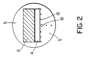
- the present invention relates to a camera 1 having a strobe 2 and a lens 3 disposed behind the strobe 2.
- the lens 3 is located behind a narrow aperture 4, preferably shaped as a slit aperture, on one side of which is the strobe 2 that provides the flash. On the opposite side of the aperture 4 is a shield 5.
- the flash be aligned as close as possible to the edge of the lens aperture and the center of the optical axis to permit detection of a red retinal reflection and to maximize the sensitivity of the system, and, by proper positioning of the flash, one can detect and analyze the light exiting from the eye which has been defocussed by the refractive error of the eye, and by analyzing the size and appearance of these white crescents within the red reflex determine, on a relative basis, the size and type of the refractive error.
- the flash is positioned to define the edge of the lens aperture. Asymmetry of crescent size or defocus indicates anisometropia, meaning unequal refractive errors, which can lead to amblyopia.
- a shutter 6 is positioned behind the strobe 2 and the aperture 4.
- the shutter 6 is wide open but can be made smaller to improve light exposure.
- the open aperture arrangement of the shutter 6 does not affect the exposed film 11 in the camera 1, rather it is the distance between the flash and the slit 4 that creates the effective aperture of the camera 1 and thus minimizes the lens/flash eccentricity of the camera 1 by placing the flash very close to the outer edge of the camera aperture (the slit 4).
- the slit 4 is preferably 3 mm wide.
- a parallax aiming system 25 is another feature of present invention. Two light images are projected onto the forehead of the patient and when the camera distance is adjusted and the lights touch each other the proper focusing distance and alignment are obtained.
- the parallax aiming system can consist of any system in which the two lights, which can be of different colors sizes or shapes, move back and forth, without necessarily touching, until proper focus, proper height and aiming alignment is achieved.
- the strobe 2 can be rotated in both the vertical, oblique and horizontal directions to permit photographing different meridians of refractive error.
- the camera 1 uses ASA 3000 black and white film but can use any front surface or back surface exposure film or video recording device.
- Two exposures are taken and placed on one sheet of film, one exposure is taken when the strobe 2 is rotated vertically and the other exposure is taken when the strobe or camera is rotated horizontally or in other oblique directions approximately 90° apart.
- the strobe 2 is tilted to place effective flash output at the edge of the strobe to minimize the eccentricity and to maximize sensitivity.
- the angled strobe 2 is rotated 90 degrees about the optical center line in order to take the vertical and horizontal or oblique pictures
- the camera 1 has three mirrors 7, 8, 9 forming a 4 reflection foldable light path thereon.
- Mirror 7 accomplishes two reflections.
- One mirror 9 is rotatable and two mirrors 7 and 8 are fixed.
- the last mirror 9 in the foldable light path is rotatable and is an image spitter as it serves to place two images on one sheet of film.
- By rotating mirror 9 a few degrees the image can be moved to either the superior or inferior half of the film.
- the two exposures, discussed above can be produced on one sheet of film.
- a rotating shield 10 is placed in front of the film 11 to shield the other half of the film from inadvertent light exposure. Light travels through the camera 1 and through the folded light path formed by the three mirrors 7, 8 and 9 therein.
- the folded light path provides for a very large focal distance thus providing a large magnification of the image resulting in an approximate one to one image size.
- a telescopic lens system can be utilized with a shorter light path to create the magnification of the image.
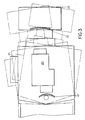
- the telescopic lens system of FIG. 3 would preferably have a monocular telescope 20 which magnifies the image.
- An imaging lens 21 focuses the magnified image onto film such as instant film that is exposed from its rear surface e.g. Polaroid black and white film.
- a projection lens 22 is provided at the front part 23 of the camera to project to infinity from the viewpoint of the telescope.
- the front part 23 of the camera would pivot as shown in FIG. 3 to direct the image to the upper and lower parts of the film.
- the rotary shield functions in the same fashion as described with regard to FIG. 1 to shield the part of the film not receiving an image.
- the front part 23 of the camera is also capable of up and down translational movement to move the image relative to the film.
- a flashing light emitting diode (LED) or series of LEDS 12, which can be red or any other color, are placed just below the slit 4 in the shield 5, to attract the fixation of the child (patient) to the center of the lens to ensure maximum sensitivity and reliability of accommodation and alignment.
- a sound generator (not shown) can also be incorporated into the camera system 1 to attract the child's attention.
- a Polaroid auto film back is placed at the focal distance of the camera and by means of a special chip and circuit board ejects the film automatically after the two exposures.
- film expulsion can be delayed until a button is pushed rather than using the chip and circuit board.
- the 1:1 magnification can be achieved by utilizing other methodology such as a telescopic lens or other magnifying system rather than the foldable mirror path.
- a three mirror, three reflection foldable light path is used and color or front exposure film is used with a flash.
- the camera 1 preferably further includes an interlock mechanism that prevents the film from being ejected until the vertical, horizontal or oblique pictures are recorded on the same sheet of film.
- the camera 1 further includes handles for portability and for holding the camera at chest or eye height.
Landscapes
- Life Sciences & Earth Sciences (AREA)
- Health & Medical Sciences (AREA)
- Medical Informatics (AREA)
- Biophysics (AREA)
- Ophthalmology & Optometry (AREA)
- Engineering & Computer Science (AREA)
- Biomedical Technology (AREA)
- Heart & Thoracic Surgery (AREA)
- Physics & Mathematics (AREA)
- Molecular Biology (AREA)
- Surgery (AREA)
- Animal Behavior & Ethology (AREA)
- General Health & Medical Sciences (AREA)
- Public Health (AREA)
- Veterinary Medicine (AREA)
- Eye Examination Apparatus (AREA)
Applications Claiming Priority (2)
| Application Number | Priority Date | Filing Date | Title |
|---|---|---|---|
| US07/387,697 US4989968A (en) | 1989-07-31 | 1989-07-31 | Photoscreening camera system |
| US387697 | 1999-08-31 |
Publications (3)
| Publication Number | Publication Date |
|---|---|
| EP0411475A2 true EP0411475A2 (fr) | 1991-02-06 |
| EP0411475A3 EP0411475A3 (en) | 1991-06-12 |
| EP0411475B1 EP0411475B1 (fr) | 1996-10-09 |
Family
ID=23531019
Family Applications (1)
| Application Number | Title | Priority Date | Filing Date |
|---|---|---|---|
| EP90114338A Expired - Lifetime EP0411475B1 (fr) | 1989-07-31 | 1990-07-26 | Système de caméra pour dépistage du défaut d'image |
Country Status (5)
| Country | Link |
|---|---|
| US (1) | US4989968A (fr) |
| EP (1) | EP0411475B1 (fr) |
| JP (1) | JPH03162821A (fr) |
| CA (1) | CA2021843C (fr) |
| DE (1) | DE69028819T2 (fr) |
Cited By (1)
| Publication number | Priority date | Publication date | Assignee | Title |
|---|---|---|---|---|
| EP2676441A4 (fr) * | 2011-02-17 | 2017-07-05 | Welch Allyn, Inc. | Dispositif et procédés de dépistage oculaire par photoréfraction |
Families Citing this family (19)
| Publication number | Priority date | Publication date | Assignee | Title |
|---|---|---|---|---|
| US5502520A (en) * | 1993-12-03 | 1996-03-26 | Cibis; Gerhard W. | Method and apparatus for detecting eye disorders |
| JP3355270B2 (ja) * | 1996-02-05 | 2002-12-09 | アルプス電気株式会社 | 発光モジュール |
| US6027216A (en) * | 1997-10-21 | 2000-02-22 | The Johns University School Of Medicine | Eye fixation monitor and tracker |
| US6007204A (en) | 1998-06-03 | 1999-12-28 | Welch Allyn, Inc. | Compact ocular measuring system |
| GB0207303D0 (en) * | 2002-03-28 | 2002-05-08 | Jordan Ian | Optical testing methods and apparatus |
| US6663242B1 (en) | 2001-03-12 | 2003-12-16 | Wayne Davenport | Simultaneous, wavelength multiplexed vision screener |
| US6616277B1 (en) | 2001-07-02 | 2003-09-09 | Vision Research Corporation | Sequential eye screening method and apparatus |
| US7427135B2 (en) * | 2006-01-24 | 2008-09-23 | University Of Tennessee Research Foundation | Adaptive photoscreening system |
| US7878652B2 (en) * | 2006-01-24 | 2011-02-01 | University Of Tennessee Research Foundation | Adaptive photoscreening system |
| JP4708491B2 (ja) * | 2007-03-29 | 2011-06-22 | 富士通株式会社 | 撮影制御装置、そのプログラム及び方法、撮影装置 |
| US8306279B2 (en) * | 2008-09-15 | 2012-11-06 | Eyelock, Inc. | Operator interface for face and iris recognition devices |
| US8437517B2 (en) | 2010-11-03 | 2013-05-07 | Lockheed Martin Corporation | Latent fingerprint detectors and fingerprint scanners therefrom |
| WO2013032867A1 (fr) | 2011-08-26 | 2013-03-07 | Lockheed Martin Corporation | Détection d'empreintes digitales latentes |
| KR20140103900A (ko) | 2011-09-08 | 2014-08-27 | 아이체크 헬스 커넥션, 인크. | 유아 및 소아에 있어서 눈의 동공 적색 반사 검사 및 각막 광 반사 선별의 기록 및 문서화를 위한 방법 및 시스템 |
| AU2012340573A1 (en) | 2011-11-21 | 2014-07-17 | Icheck Health Connection, Inc. | Video game to monitor retinal diseases |
| US9433346B2 (en) | 2011-11-21 | 2016-09-06 | Gobiquity, Inc. | Circular preferential hyperacuity perimetry video game to monitor macular and retinal diseases |
| US10327951B2 (en) * | 2014-02-28 | 2019-06-25 | Excel-Lens, Inc. | Laser assisted cataract surgery |
| US9804096B1 (en) | 2015-01-14 | 2017-10-31 | Leidos Innovations Technology, Inc. | System and method for detecting latent images on a thermal dye printer film |
| US10506165B2 (en) | 2015-10-29 | 2019-12-10 | Welch Allyn, Inc. | Concussion screening system |
Family Cites Families (6)
| Publication number | Priority date | Publication date | Assignee | Title |
|---|---|---|---|---|
| US4209252A (en) * | 1978-07-03 | 1980-06-24 | Arditty Herve J | Optical probe assembly for detecting the position of an object surface and method |
| NZ202116A (en) * | 1982-10-08 | 1986-09-10 | A C B Molteno | Photographic testing of eye focussing defects |
| JPS59151935A (ja) * | 1983-02-18 | 1984-08-30 | 株式会社トプコン | 眼底カメラ |
| US4711541A (en) * | 1984-02-02 | 1987-12-08 | Tokyo Kogaku Kikai Kabushiki Kaisha | Slit lamp and accessory device thereof |
| US4717952A (en) * | 1985-06-14 | 1988-01-05 | Canon Kabushiki Kaisha | Medical television system |
| USH574H (en) * | 1987-08-28 | 1989-02-07 | The United States Of America As Represented By The Secretary Of The Air Force | Subject operated pupilometer |
-
1989
- 1989-07-31 US US07/387,697 patent/US4989968A/en not_active Expired - Lifetime
-
1990
- 1990-07-24 CA CA002021843A patent/CA2021843C/fr not_active Expired - Fee Related
- 1990-07-26 DE DE69028819T patent/DE69028819T2/de not_active Expired - Fee Related
- 1990-07-26 EP EP90114338A patent/EP0411475B1/fr not_active Expired - Lifetime
- 1990-07-31 JP JP2203779A patent/JPH03162821A/ja active Pending
Cited By (2)
| Publication number | Priority date | Publication date | Assignee | Title |
|---|---|---|---|---|
| EP2676441A4 (fr) * | 2011-02-17 | 2017-07-05 | Welch Allyn, Inc. | Dispositif et procédés de dépistage oculaire par photoréfraction |
| EP3566638A1 (fr) * | 2011-02-17 | 2019-11-13 | Welch Allyn, INC. | Dispositif et procédés de criblage oculaire de photoréfraction |
Also Published As
| Publication number | Publication date |
|---|---|
| CA2021843A1 (fr) | 1991-02-01 |
| DE69028819T2 (de) | 1997-05-28 |
| EP0411475A3 (en) | 1991-06-12 |
| CA2021843C (fr) | 1998-10-13 |
| EP0411475B1 (fr) | 1996-10-09 |
| JPH03162821A (ja) | 1991-07-12 |
| DE69028819D1 (de) | 1996-11-14 |
| US4989968A (en) | 1991-02-05 |
Similar Documents
| Publication | Publication Date | Title |
|---|---|---|
| US4989968A (en) | Photoscreening camera system | |
| JP2942321B2 (ja) | 徹照像撮影装置 | |
| US6193371B1 (en) | Keratometer/pachymeter | |
| EP0962184A1 (fr) | Système compacte pour la mesure de la réfraction de l'oeil | |
| KR20110086004A (ko) | 안구 촬영 장치 및 방법 | |
| JPS5843090B2 (ja) | 調整システムを備えた眼科装置 | |
| CN109381158A (zh) | 适配器、包含适配器的眼底照相系统及其使用方法 | |
| US5315329A (en) | Simultaneous stereo fundus camera | |
| JPH08564A (ja) | 眼科装置 | |
| US5475451A (en) | Ophthalmologic apparatus | |
| JPH0646995A (ja) | 眼屈折計 | |
| JPH0833610A (ja) | 眼科撮影装置 | |
| JP2000135200A (ja) | 検眼装置 | |
| US5262806A (en) | Photo-deviometer | |
| JP2812421B2 (ja) | 角膜細胞撮影装置 | |
| JPH02264632A (ja) | 視線検出装置 | |
| JPH0975308A (ja) | 角膜内皮細胞撮影装置 | |
| JP3332489B2 (ja) | 検眼装置 | |
| JPH0759231B2 (ja) | 前眼部断面撮影装置 | |
| FR2461481A1 (fr) | Appareil de prise de vues de l'iris | |
| JP2001161644A (ja) | 検眼装置 | |
| JPS6057856B2 (ja) | 固視装置を内蔵した眼底カメラ | |
| JPS6034378B2 (ja) | 眼底カメラ | |
| JP3260034B2 (ja) | カメラ | |
| JP3255240B2 (ja) | 眼科装置 |
Legal Events
| Date | Code | Title | Description |
|---|---|---|---|
| PUAI | Public reference made under article 153(3) epc to a published international application that has entered the european phase |
Free format text: ORIGINAL CODE: 0009012 |
|
| AK | Designated contracting states |
Kind code of ref document: A2 Designated state(s): DE FR GB IT |
|
| PUAL | Search report despatched |
Free format text: ORIGINAL CODE: 0009013 |
|
| AK | Designated contracting states |
Kind code of ref document: A3 Designated state(s): DE FR GB IT |
|
| 17P | Request for examination filed |
Effective date: 19911129 |
|
| 17Q | First examination report despatched |
Effective date: 19930924 |
|
| GRAH | Despatch of communication of intention to grant a patent |
Free format text: ORIGINAL CODE: EPIDOS IGRA |
|
| GRAH | Despatch of communication of intention to grant a patent |
Free format text: ORIGINAL CODE: EPIDOS IGRA |
|
| GRAA | (expected) grant |
Free format text: ORIGINAL CODE: 0009210 |
|
| AK | Designated contracting states |
Kind code of ref document: B1 Designated state(s): DE FR GB IT |
|
| REF | Corresponds to: |
Ref document number: 69028819 Country of ref document: DE Date of ref document: 19961114 |
|
| ITF | It: translation for a ep patent filed | ||
| ET | Fr: translation filed | ||
| PLBE | No opposition filed within time limit |
Free format text: ORIGINAL CODE: 0009261 |
|
| STAA | Information on the status of an ep patent application or granted ep patent |
Free format text: STATUS: NO OPPOSITION FILED WITHIN TIME LIMIT |
|
| 26N | No opposition filed | ||
| REG | Reference to a national code |
Ref country code: GB Ref legal event code: IF02 |
|
| PGFP | Annual fee paid to national office [announced via postgrant information from national office to epo] |
Ref country code: GB Payment date: 20030730 Year of fee payment: 14 |
|
| PGFP | Annual fee paid to national office [announced via postgrant information from national office to epo] |
Ref country code: DE Payment date: 20030807 Year of fee payment: 14 |
|
| PGFP | Annual fee paid to national office [announced via postgrant information from national office to epo] |
Ref country code: FR Payment date: 20030808 Year of fee payment: 14 |
|
| PG25 | Lapsed in a contracting state [announced via postgrant information from national office to epo] |
Ref country code: GB Free format text: LAPSE BECAUSE OF NON-PAYMENT OF DUE FEES Effective date: 20040726 |
|
| PG25 | Lapsed in a contracting state [announced via postgrant information from national office to epo] |
Ref country code: DE Free format text: LAPSE BECAUSE OF NON-PAYMENT OF DUE FEES Effective date: 20050201 |
|
| GBPC | Gb: european patent ceased through non-payment of renewal fee |
Effective date: 20040726 |
|
| PG25 | Lapsed in a contracting state [announced via postgrant information from national office to epo] |
Ref country code: FR Free format text: LAPSE BECAUSE OF NON-PAYMENT OF DUE FEES Effective date: 20050331 |
|
| REG | Reference to a national code |
Ref country code: FR Ref legal event code: ST |
|
| PG25 | Lapsed in a contracting state [announced via postgrant information from national office to epo] |
Ref country code: IT Free format text: LAPSE BECAUSE OF NON-PAYMENT OF DUE FEES;WARNING: LAPSES OF ITALIAN PATENTS WITH EFFECTIVE DATE BEFORE 2007 MAY HAVE OCCURRED AT ANY TIME BEFORE 2007. THE CORRECT EFFECTIVE DATE MAY BE DIFFERENT FROM THE ONE RECORDED. Effective date: 20050726 |