EP0411480A2 - Structure porteuse d'essai - Google Patents
Structure porteuse d'essai Download PDFInfo
- Publication number
- EP0411480A2 EP0411480A2 EP90114395A EP90114395A EP0411480A2 EP 0411480 A2 EP0411480 A2 EP 0411480A2 EP 90114395 A EP90114395 A EP 90114395A EP 90114395 A EP90114395 A EP 90114395A EP 0411480 A2 EP0411480 A2 EP 0411480A2
- Authority
- EP
- European Patent Office
- Prior art keywords
- basket
- chassis
- roof
- devices
- opening
- Prior art date
- Legal status (The legal status is an assumption and is not a legal conclusion. Google has not performed a legal analysis and makes no representation as to the accuracy of the status listed.)
- Granted
Links
Images

Classifications
-
- F—MECHANICAL ENGINEERING; LIGHTING; HEATING; WEAPONS; BLASTING
- F41—WEAPONS
- F41H—ARMOUR; ARMOURED TURRETS; ARMOURED OR ARMED VEHICLES; MEANS OF ATTACK OR DEFENCE, e.g. CAMOUFLAGE, IN GENERAL
- F41H7/00—Armoured or armed vehicles
- F41H7/02—Land vehicles with enclosing armour, e.g. tanks
Definitions
- the invention relates to a test vehicle with a chassis and an opening in the chassis dimensioned for a tower or the like, which can be exchangeably received in an opening dimensioned for a tower or the like in the chassis of a combat vehicle.
- test vehicles When designing new types of combat vehicles, the design and development are checked through investigations with test vehicles, which can be divided into three groups according to their main uses: - Module test carriers are used to test and optimize individual modules, such as the weapon leveling system, reconnaissance modules and fire control sensors; - Process test vehicles serve to develop concept-specific processes such as shooting processes and fire control functions, but also to check logistical and tactical aspects; - Configuration test vehicles are used to determine the optimal configuration, including the geometric aspects of the assemblies and processes.
- modules test carriers are used to test and optimize individual modules, such as the weapon leveling system, reconnaissance modules and fire control sensors;
- - Process test vehicles serve to develop concept-specific processes such as shooting processes and fire control functions, but also to check logistical and tactical aspects;
- - Configuration test vehicles are used to determine the optimal configuration, including the geometric aspects of the assemblies and processes.
- Processes, systems and assemblies are improved in iterative optimization, whereby an interaction between the optimization cycles for coordinating the assemblies, systems and processes has to be established.
- the invention has for its object to provide a test vehicle of the type mentioned, which is easily adaptable to different configuration methods and enables interactive module optimization with little effort.
- a combat area container can be used interchangeably in the opening, which carries components and / or devices to be tested, that the combat area container has a basket which is detachably connected to the chassis and which is covered by a roof which is detachably connected thereto is that the basket holds largely invariant assemblies and / or devices, and that the roof can be varied more frequently Assemblies and / or devices.
- test vehicle according to the invention With the test vehicle according to the invention it is achieved that a "concept rigidity" is avoided in the advanced stage of system development.
- the test vehicle according to the invention allows the optimization of configurations and assemblies - under the dynamic conditions of field and field tests, - with the involvement of the team as an integral part of the system, - parallel to configuration and module optimization and - not only after complete technical maturity of concept-specific assemblies, without having to create a new test vehicle every time individual, sensitive system parameters, assemblies and / or devices are changed.
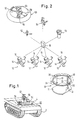
- FIG. 1 shows a test vehicle according to the invention.
- a chassis 20 has a chain drive 2 and includes a drive and a driver's seat (not shown).
- An opening is provided in the chassis 20, which receives a combat area container 4.
- Only one roof 50 of this combat area container 4 can be seen in the illustration according to FIG. 1, which roof carries various devices.
- These devices include a simulated weapon system, for example in the form of a laser shot simulator 56, a sighting device 54, an observation device 52 and a stabilized viewing device 58 (DE-PS 33 28 031).
- the combat area container 4 comprises a basket 10 which can be inserted into the opening of the tub 20 and releasably connected thereto, as explained in detail with reference to FIG. 3.
- the basket 10 contains battlegrounds 12 (in the exemplary embodiment shown a total of 4 battlegrounds), each of which includes a directional handle 14 and a monitor 16. Furthermore, central electronics 18 are accommodated in the basket 10.
- the basket 10 itself has a base 11 which is supported by vertical struts 13 via shock absorbers 30 on a support ring 32 belonging to the basket 10.
- three struts 13, each with a shock absorber 30 in the form of a rubber element are offset by 90 ° from one another.
- a stabilized azimuth drive 24 via which the basket can be driven in rotation in the opening of the chassis 20.
- the devices 52 to 58 are easily replaceable in the roof 50. All of the components 12 to 18 and 52 to 58 arranged in the combat area container 4 are effectively protected against vibrations due to the shock-absorbing suspension, which are communicated to the chassis when the test vehicle is traveling over uneven ground.
- Fig. 3 shows the construction of the combat area container 4 in detail.
- the inner edge of the opening in the chassis 20 is surrounded by an annular flange 21 which carries a fixed bearing ring 23 in its upper part and a fixed slewing ring 22 with ring gear teeth 25 in its lower part.
- a wire bearing 34 is arranged between the fixed bearing ring 23 and an inner bearing ring 27. With the inner bearing ring 27, a support ring 32 is connected, each carrying brackets 33 offset by 90 o .
- the three struts 13 of the basket 10 are supported on the brackets 33 by rubber elements 30.
- the structure and mode of operation of this azimuth drive are known (DE-PS 27 27 582) and are therefore not described in detail.
- a support structure with an upper ring 17 and a lower ring 19 is connected to the upper end of the struts 13.
- the roof 50 is detachably connected via screws 51.
- the interior of the basket 10 is sealed off from the external environment by means of a sealing ring 31 which is formed in a support ring 32 Groove is received and is pressed with its top to the bottom of the lower ring 19 of the support structure 17, 19 of the basket 10.
- roof 50 and thus the assemblies and / or devices carried by the roof 50 are easily removed and serviced after loosening the screws 51 from the basket 10 mounted in the opening or by a roof equipped with other assemblies and / or devices can be exchanged. This shortens the testing of new assemblies and / or components in field trials.
Landscapes
- Engineering & Computer Science (AREA)
- General Engineering & Computer Science (AREA)
- Aiming, Guidance, Guns With A Light Source, Armor, Camouflage, And Targets (AREA)
- Testing Of Devices, Machine Parts, Or Other Structures Thereof (AREA)
- Investigating Strength Of Materials By Application Of Mechanical Stress (AREA)
- Body Structure For Vehicles (AREA)
Applications Claiming Priority (2)
| Application Number | Priority Date | Filing Date | Title |
|---|---|---|---|
| DE3925616A DE3925616A1 (de) | 1989-08-02 | 1989-08-02 | Versuchstraeger |
| DE3925616 | 1989-08-02 |
Publications (3)
| Publication Number | Publication Date |
|---|---|
| EP0411480A2 true EP0411480A2 (fr) | 1991-02-06 |
| EP0411480A3 EP0411480A3 (en) | 1992-06-17 |
| EP0411480B1 EP0411480B1 (fr) | 1995-05-24 |
Family
ID=6386380
Family Applications (1)
| Application Number | Title | Priority Date | Filing Date |
|---|---|---|---|
| EP90114395A Expired - Lifetime EP0411480B1 (fr) | 1989-08-02 | 1990-07-26 | Structure porteuse d'essai |
Country Status (3)
| Country | Link |
|---|---|
| US (1) | US5079960A (fr) |
| EP (1) | EP0411480B1 (fr) |
| DE (2) | DE3925616A1 (fr) |
Families Citing this family (13)
| Publication number | Priority date | Publication date | Assignee | Title |
|---|---|---|---|---|
| DE19638375A1 (de) * | 1996-09-19 | 1998-03-26 | Esg Elektroniksystem Und Logis | Mobiles System zur Detektion und/oder Beseitigung oder Neutralisation von Minen unter Panzerungsschutz |
| DE19826615A1 (de) * | 1998-06-17 | 1999-12-23 | Busch Dieter & Co Prueftech | Stoßschutz für Lagemess-Sonden |
| RU2154794C1 (ru) * | 1999-09-08 | 2000-08-20 | Общевойсковая Академия Вооруженных Сил Российской Федерации | Способ замены башни боевой машины пехоты |
| DE10127742A1 (de) * | 2001-06-08 | 2002-12-12 | Krauss Maffei Wegmann Gmbh & C | Schützenpanzer |
| DE10144366A1 (de) * | 2001-09-10 | 2003-03-27 | Rheinmetall Landsysteme Gmbh | Container-Adapter für ein gepanzertes Transportfahrzeug |
| DE10160215A1 (de) * | 2001-12-07 | 2003-06-26 | Rheinmetall Landsysteme Gmbh | Multifunktionaler Aufnahmering für gepanzerte Fahrzeuge |
| DE10337643A1 (de) * | 2003-08-16 | 2005-03-10 | Krauss Maffei Wegmann Gmbh & C | Deckel für einen im Turm oder der Fahrzeugwanne eines Kampffahrzeugs angeordneten Munitionsraum |
| DE102004027768B4 (de) * | 2004-06-08 | 2006-03-02 | Rheinmetall Landsysteme Gmbh | Sitzeinrichtung, insbesondere für ein militärisches Fahrzeug |
| DE102010007432A1 (de) * | 2010-02-09 | 2011-08-11 | Rheinmetall Landsysteme GmbH, 24107 | Kampfpanzer mit einer Besatzung im Turm |
| IL207237A (en) | 2010-07-26 | 2014-03-31 | Plasan Sasa Ltd | Support for machine gun position |
| CN102279109B (zh) * | 2011-04-07 | 2013-03-20 | 晁智强 | 军用车辆底盘部分信号通用测试装置 |
| DE102012102235C5 (de) | 2012-03-16 | 2017-10-26 | Krauss-Maffei Wegmann Gmbh & Co. Kg | Militärisches Fahrzeug und Verfahren zur Ausrichtung eines Ausrüstungsgegenstands |
| DE102013101635A1 (de) | 2013-02-19 | 2014-08-21 | Krauss-Maffei Wegmann Gmbh & Co. Kg | Waffenstation |
Family Cites Families (18)
| Publication number | Priority date | Publication date | Assignee | Title |
|---|---|---|---|---|
| AT27655B (de) * | 1906-06-13 | 1907-02-25 | Saurer Fa Adolph | Klappenabschluß für Karburatoren mit mehreren Gemischwegen. |
| US2446566A (en) * | 1946-01-22 | 1948-08-10 | Jr Edward Wenk | Model testing apparatus |
| US2701963A (en) * | 1954-07-19 | 1955-02-15 | Charles E Balleisen | Experimental machine gun mount |
| US2891398A (en) * | 1957-04-29 | 1959-06-23 | Magnavox Co | Multi speed centrifuge |
| FR2011747A1 (fr) * | 1968-06-28 | 1970-03-06 | Cadillac Gage Ste | |
| US3751973A (en) * | 1971-02-08 | 1973-08-14 | Glass Containers Corp | Apparatus and method for pressure testing containers |
| US3761806A (en) * | 1972-05-24 | 1973-09-25 | Kahle Eng Co | Automatic capacitor inspection machine |
| FR2297461A1 (fr) * | 1975-01-10 | 1976-08-06 | Martel Marius | Dispositif pour le controle des boules a jouer |
| US4163142A (en) * | 1977-02-14 | 1979-07-31 | Avon Products, Inc. | Method and apparatus for assembling rings |
| DE2727582C1 (de) * | 1977-06-20 | 1985-10-10 | IBP Pietzsch GmbH, 7505 Ettlingen | Vorrichtung zur Positionierung und Lagestabilisierung einer schwenkbar auf einer Unterlage gelagerten trbgen Mass? |
| DE3113404A1 (de) * | 1981-04-03 | 1982-10-21 | Mak Maschinenbau Krupp | Kettenfahrzeug, insbesondere panzerfahrzeug |
| JPS60501621A (ja) * | 1983-06-22 | 1985-09-26 | エイエム ゼネラル コ−ポレ−シヨン | 軽量軍用車両用砲塔装置 |
| DE3328031A1 (de) * | 1983-08-03 | 1985-02-14 | IBP Pietzsch GmbH, 7505 Ettlingen | Vorrichtung zur positionierung und lagestabilisierung |
| HU186814B (en) * | 1983-11-14 | 1985-09-30 | Transinnov Koezlekedesi Muesza | Method and apparatus for qualifying the shock absorption of sprung running gear provided with felxible tyre particularly for road motor vehicle one |
| US4732036A (en) * | 1985-05-10 | 1988-03-22 | Weeder Allen F | Automatic transmission test apparatus |
| US4667506A (en) * | 1985-12-02 | 1987-05-26 | Crown Cork & Seal Canada Inc. | High pressure container tester |
| DE3618885A1 (de) * | 1986-06-05 | 1987-12-10 | Pietzsch Ibp Gmbh | Fahrzeug fuer katastrophenschutz, insbesondere in kerntechnischen anlagen |
| US4843895A (en) * | 1988-03-24 | 1989-07-04 | Harper Andrew K | Test stand for R/C vehicles |
-
1989
- 1989-08-02 DE DE3925616A patent/DE3925616A1/de active Granted
-
1990
- 1990-07-26 DE DE59009116T patent/DE59009116D1/de not_active Expired - Fee Related
- 1990-07-26 EP EP90114395A patent/EP0411480B1/fr not_active Expired - Lifetime
- 1990-07-30 US US07/564,533 patent/US5079960A/en not_active Expired - Fee Related
Also Published As
| Publication number | Publication date |
|---|---|
| DE59009116D1 (de) | 1995-06-29 |
| HK1002714A1 (en) | 1998-09-11 |
| DE3925616C2 (fr) | 1991-06-13 |
| EP0411480B1 (fr) | 1995-05-24 |
| US5079960A (en) | 1992-01-14 |
| EP0411480A3 (en) | 1992-06-17 |
| DE3925616A1 (de) | 1991-02-07 |
Similar Documents
| Publication | Publication Date | Title |
|---|---|---|
| EP0411480B1 (fr) | Structure porteuse d'essai | |
| DE2903856C2 (de) | Vorrichtung zur Dämpfung der Rotorschwingungen eines Drehflüglers | |
| DE3931753C2 (fr) | ||
| DE69724384T2 (de) | Redundantes, vorderes Aufhängungssytem für ein Turbotriebwerk | |
| EP1769174B1 (fr) | Differentiel pour essieu de vehicule | |
| DE3102566A1 (de) | Vorrichtung zur erzeugung von bewegungen mit drei oder vier freiheitsgraden | |
| DE2804129A1 (de) | Portalschlepper | |
| DE69818200T2 (de) | Befestigung einer Ausrüstungshalterung an Bord eines Luftfahrzeuges | |
| DE2613734B1 (de) | Vorrichtung zum ueben im betaetigen eines fernsteuerbaren modellhubschraubers | |
| DE3828285A1 (de) | Zentrifuge | |
| EP3336254B1 (fr) | Engin de construction et procédé de conversion de l'engin de construction pour l'usinage d'un revêtement de sol | |
| DE102017119020A1 (de) | Testaufbau für Traktions-Batterie-Systeme von Kraftfahrzeugen | |
| DE3719064A1 (de) | Roboterhandgelenk | |
| DE112015000169B4 (de) | Steuerungs-Baugruppe und Arbeitsfahrzeug | |
| DE3048922A1 (de) | Anschluss einer turasnabe an dem fahrgetriebe eines kettenfahrzeuges | |
| DE2634776A1 (de) | Mittenfreie, vertikalachsige waelzlagerdrehverbindung | |
| DE102013212341A1 (de) | Lüftervorrichtung und Verfahren zur Auswuchtung | |
| DE102017101779B4 (de) | Fixiervorrichtung zur verwendung bei der wartung einer baumaschine sowie verfahren zur wartung einer baumaschine unter verwendung solch einer fixiervorrichtung | |
| EP0411450B1 (fr) | Dispositif d'appui pour le boîtier du différentiel d'un véhicule | |
| DE4035071C2 (fr) | ||
| DE102020120166A1 (de) | Prüfstand für ein Kraftfahrzeug und Verfahren zum Durchführen einer Kraftfahrzeugprüfung | |
| EP0992967B1 (fr) | Simulateur d'entraînement | |
| DE2106662A1 (de) | Antrieb für elektrische Triebfahrzeuge | |
| DE3124525C2 (de) | Flugkörper | |
| EP1975064A1 (fr) | Aéronef |
Legal Events
| Date | Code | Title | Description |
|---|---|---|---|
| PUAI | Public reference made under article 153(3) epc to a published international application that has entered the european phase |
Free format text: ORIGINAL CODE: 0009012 |
|
| AK | Designated contracting states |
Kind code of ref document: A2 Designated state(s): DE FR GB IT SE |
|
| PUAL | Search report despatched |
Free format text: ORIGINAL CODE: 0009013 |
|
| AK | Designated contracting states |
Kind code of ref document: A3 Designated state(s): DE FR GB IT SE |
|
| 17P | Request for examination filed |
Effective date: 19920523 |
|
| 17Q | First examination report despatched |
Effective date: 19940208 |
|
| GRAA | (expected) grant |
Free format text: ORIGINAL CODE: 0009210 |
|
| AK | Designated contracting states |
Kind code of ref document: B1 Designated state(s): DE FR GB IT SE |
|
| GBT | Gb: translation of ep patent filed (gb section 77(6)(a)/1977) |
Effective date: 19950523 |
|
| REF | Corresponds to: |
Ref document number: 59009116 Country of ref document: DE Date of ref document: 19950629 |
|
| ITF | It: translation for a ep patent filed | ||
| ET | Fr: translation filed | ||
| PLBE | No opposition filed within time limit |
Free format text: ORIGINAL CODE: 0009261 |
|
| STAA | Information on the status of an ep patent application or granted ep patent |
Free format text: STATUS: NO OPPOSITION FILED WITHIN TIME LIMIT |
|
| 26N | No opposition filed | ||
| PGFP | Annual fee paid to national office [announced via postgrant information from national office to epo] |
Ref country code: DE Payment date: 19970716 Year of fee payment: 9 |
|
| PGFP | Annual fee paid to national office [announced via postgrant information from national office to epo] |
Ref country code: SE Payment date: 19980707 Year of fee payment: 9 |
|
| PGFP | Annual fee paid to national office [announced via postgrant information from national office to epo] |
Ref country code: FR Payment date: 19980709 Year of fee payment: 9 |
|
| PGFP | Annual fee paid to national office [announced via postgrant information from national office to epo] |
Ref country code: GB Payment date: 19980717 Year of fee payment: 9 |
|
| PG25 | Lapsed in a contracting state [announced via postgrant information from national office to epo] |
Ref country code: GB Free format text: LAPSE BECAUSE OF NON-PAYMENT OF DUE FEES Effective date: 19990726 |
|
| PG25 | Lapsed in a contracting state [announced via postgrant information from national office to epo] |
Ref country code: SE Free format text: THE PATENT HAS BEEN ANNULLED BY A DECISION OF A NATIONAL AUTHORITY Effective date: 19990730 |
|
| PG25 | Lapsed in a contracting state [announced via postgrant information from national office to epo] |
Ref country code: FR Free format text: THE PATENT HAS BEEN ANNULLED BY A DECISION OF A NATIONAL AUTHORITY Effective date: 19990731 |
|
| GBPC | Gb: european patent ceased through non-payment of renewal fee |
Effective date: 19990726 |
|
| EUG | Se: european patent has lapsed |
Ref document number: 90114395.8 |
|
| PG25 | Lapsed in a contracting state [announced via postgrant information from national office to epo] |
Ref country code: DE Free format text: LAPSE BECAUSE OF NON-PAYMENT OF DUE FEES Effective date: 20000503 |
|
| REG | Reference to a national code |
Ref country code: FR Ref legal event code: ST |
|
| PG25 | Lapsed in a contracting state [announced via postgrant information from national office to epo] |
Ref country code: IT Free format text: LAPSE BECAUSE OF NON-PAYMENT OF DUE FEES Effective date: 20050726 |