EP0411488A1 - Réservoir de sang pour un appareil médical - Google Patents
Réservoir de sang pour un appareil médical Download PDFInfo
- Publication number
- EP0411488A1 EP0411488A1 EP90114436A EP90114436A EP0411488A1 EP 0411488 A1 EP0411488 A1 EP 0411488A1 EP 90114436 A EP90114436 A EP 90114436A EP 90114436 A EP90114436 A EP 90114436A EP 0411488 A1 EP0411488 A1 EP 0411488A1
- Authority
- EP
- European Patent Office
- Prior art keywords
- blood
- outer housing
- filter
- housing
- bottom portion
- Prior art date
- Legal status (The legal status is an assumption and is not a legal conclusion. Google has not performed a legal analysis and makes no representation as to the accuracy of the status listed.)
- Granted
Links
- 210000004369 blood Anatomy 0.000 title claims abstract description 47
- 239000008280 blood Substances 0.000 title claims abstract description 47
- 238000007599 discharging Methods 0.000 claims abstract description 4
- 238000005192 partition Methods 0.000 claims description 8
- 210000000601 blood cell Anatomy 0.000 abstract description 5
- 230000005779 cell damage Effects 0.000 abstract description 4
- 208000037887 cell injury Diseases 0.000 abstract description 4
- 230000017531 blood circulation Effects 0.000 description 4
- 230000005484 gravity Effects 0.000 description 3
- 230000015572 biosynthetic process Effects 0.000 description 2
- 230000036765 blood level Effects 0.000 description 2
- 230000000670 limiting effect Effects 0.000 description 2
- 241001552669 Adonis annua Species 0.000 description 1
- 230000001112 coagulating effect Effects 0.000 description 1
- 238000001914 filtration Methods 0.000 description 1
- 208000014674 injury Diseases 0.000 description 1
- 239000000463 material Substances 0.000 description 1
- 230000001766 physiological effect Effects 0.000 description 1
- 229920003023 plastic Polymers 0.000 description 1
- 230000008733 trauma Effects 0.000 description 1
Images
Classifications
-
- A—HUMAN NECESSITIES
- A61—MEDICAL OR VETERINARY SCIENCE; HYGIENE
- A61M—DEVICES FOR INTRODUCING MEDIA INTO, OR ONTO, THE BODY; DEVICES FOR TRANSDUCING BODY MEDIA OR FOR TAKING MEDIA FROM THE BODY; DEVICES FOR PRODUCING OR ENDING SLEEP OR STUPOR
- A61M1/00—Suction or pumping devices for medical purposes; Devices for carrying-off, for treatment of, or for carrying-over, body-liquids; Drainage systems
- A61M1/36—Other treatment of blood in a by-pass of the natural circulatory system, e.g. temperature adaptation, irradiation ; Extra-corporeal blood circuits
- A61M1/3621—Extra-corporeal blood circuits
- A61M1/3627—Degassing devices; Buffer reservoirs; Drip chambers; Blood filters
-
- Y—GENERAL TAGGING OF NEW TECHNOLOGICAL DEVELOPMENTS; GENERAL TAGGING OF CROSS-SECTIONAL TECHNOLOGIES SPANNING OVER SEVERAL SECTIONS OF THE IPC; TECHNICAL SUBJECTS COVERED BY FORMER USPC CROSS-REFERENCE ART COLLECTIONS [XRACs] AND DIGESTS
- Y10—TECHNICAL SUBJECTS COVERED BY FORMER USPC
- Y10S—TECHNICAL SUBJECTS COVERED BY FORMER USPC CROSS-REFERENCE ART COLLECTIONS [XRACs] AND DIGESTS
- Y10S128/00—Surgery
- Y10S128/03—Heart-lung
Definitions
- the invention relates to a blood container known as a cardiotomy reservoir for medical apparatus.
- Medical apparatus for example, of cardiotomies and oxygenators are well-known which include a blood container which has a filter which receives the inflowing blood.
- a blood container which has a filter which receives the inflowing blood.
- the blood flows through the filter without stagnating or coagulating to avoid reducing filtration effectiveness and lowering the physiological properties of the blood.
- This requirement leads to containers in which the blood can be kept at a distinctly lower level than the base of the filter, in a reservoir which readily provide a good read out scale of the free surface level and blood volume in order to facilitate the operator in his functions.
- the blood drops by gravity from the level of the base of the filter to the level of the underlying free surface, and this consequently causes a severe danger of formation of bubbles and microemboli and of blood cell damage.
- An object of the present invention is to provide a blood container for medical apparatus in which the blood flows through the filter and descends gradually and smoothly toward the underlying free surface and outlet in such a manner as to ensure the absence of bubbles and provide assurances against any blood cell trauma.
- a blood container comprising a generally cylindrically shaped outer housing having an upper portion, a lower portion and a bottom portion which declines downwardly to an outlet; a generally cylindrically shaped filter enclosed concentrically within the upper portion of the upper housing for receiving blood at the top thereof and discharging filtered blood at the wall and base thereof; and a generally cylindrically shaped inner housing extending from the base of the filter to the bottom portion of the outer housing.
- the container includes by means for directing and restricting the flow of blood from the base of the filter for a gradual and smooth descent to the outlet.
- the flow directing means comprises a plurality of horizontal radial steps formed in the bottom portion; a plurality of radial baffles extending vertically from the bottom portion, an arcuate partition extending from the inner housing above the outlet of the inner housing; and a plurality of flutes extending radially from the inner housing.
- the flow directing means comprises the inner housing further comprises a partially annular duct for directing blood from the base of the filter to the upper end of the declined bottom portion of the outer housing and a plurality of radial partitions extending vertically generally between the inner housing and the outer housing for restricting the flow path between the outer housing and the inner housing.
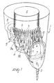
- a blood container comprises a generally cylindrically shaped outer housing 1 enclosing a concentric filter 2 within the upper portion thereof, and which has a bottom portion which declines downwardly to an outlet 3.
- the container includes an inlet (not shown) for receiving blood within the interior of the filter.
- the outer housing is preferably formed of a suitable transparent plastic material.
- the container includes a generally cylindrically shaped inner housing 4 which extends from the base of the filter to the bottom portion of the container.
- the inner housing 4 is provided with radial ridges or flutes 5 which define a plurality of ducts for the gravity descent of the blood in streams 6 which adhere to the wall and flow toward the free blood level surface 7 proximate to the bottom portion of the container.
- a partially annular planar surface 8 is provided near the base of the filter 2 and forms the uppermost surface of the declined bottom portion of the housing.
- the declined bottom continues downwardly via a series of generally horizontal radial steps 9 and 10 which are interconnected by sloping surfaces and which tend to help control the gradual descent of the blood.
- the bottom portion further includes a series of ridges or baffles 9a and 9b which extend vertically from the bottom portion and extend radially from the inner housing 4 to form a narrow opening adjacent to the outer housing to further provide a gradual and smooth descent of the blood flow.
- the container of the invention provides the desired advantages in which the blood quickly and smoothly passes through the filter and descends gradually and smoothly to the free surface.
- An operator can easily keep the free surface 7 of the blood well below the base of the filter 2 by means of an appropriate choice of the operating parameters.
- a blood level or blood volume scale indicating the level of the free surface 7, can be provided on the transparent housing above the outlet to further facilitate the utility of the container.
- the smooth gradual gravity descent of the blood toward the free surface 7 and the outlet occurs by virtue of the described system of ridges and baffles which divide the entire flow of blood into small streams which flow in contact with the walls of the housing, so as to avoid the forming of bubbles and any blood cell damage.
- a further variation of the described embodiment can be provided in which the flutes 5 extend radially from the inner housing 4 to a position closely adjacent the outer housing 1; thereby providing the function of both the flutes 5 and the baffles 9a and 9b to direct and control the flow of blood for a gradual and smooth descent to the free surface 7.
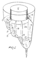
- Figure 2 illustrates a second embodiment of a blood container which comprises a cylindrically shaped outer housing and a steeped sloping bottom portion 13, 15 and 16 which declines downwardly similarly to the outer housing of Figure 1.
- the housing encloses a concentric filter 12 in the upper portion thereof and for receiving blood from an inlet (not shown) and discharging blood from the wall of the filter.
- the container includes a generally cylindrically shaped inner housing which extends from the base of the filter to the bottom portion of the outer housing.
- the bottom portion includes the partially annular planer surface 13 at the uppermost part thereof near the base of the filter for receiving flow directly from a portion of the filter.
- the inner housing includes a partially annular duct formed by a surface 14 and a flange 14a which partially encircles the base of the filter and directs the remainder of the flow from the filter onto surface 13.
- the container includes radial partitions 17, 18 and 19 extending vertically from the bottom portion between the inner housing and the outer housing and having alternate passageways near the inner and outer housing walls for directing flow to the free surface 20 and the outlet.
- the blood flow thus descends quickly and completely through the filter 12; and then partially directly and partially by duct 14 and 14a onto the surface 13; and then along the stepped declined sloped bottom portion 15, 16 and 17 and is then directed and retarded by the partitions 17, 18 and 19 alternately along the inner wall and along the outer wall to smoothly control the descent of the blood in a manner which avoids the formation of bubbles or microemboli and blood cell damage.
Landscapes
- Health & Medical Sciences (AREA)
- Heart & Thoracic Surgery (AREA)
- Vascular Medicine (AREA)
- Life Sciences & Earth Sciences (AREA)
- General Health & Medical Sciences (AREA)
- Anesthesiology (AREA)
- Biomedical Technology (AREA)
- Hematology (AREA)
- Cardiology (AREA)
- Animal Behavior & Ethology (AREA)
- Engineering & Computer Science (AREA)
- Public Health (AREA)
- Veterinary Medicine (AREA)
- External Artificial Organs (AREA)
- Medical Preparation Storing Or Oral Administration Devices (AREA)
- Prostheses (AREA)
- Ultra Sonic Daignosis Equipment (AREA)
Applications Claiming Priority (2)
| Application Number | Priority Date | Filing Date | Title |
|---|---|---|---|
| IT8921387A IT1231024B (it) | 1989-07-31 | 1989-07-31 | Contenitore di sangue per apparecchio medicale |
| IT2138789 | 1989-07-31 |
Publications (2)
| Publication Number | Publication Date |
|---|---|
| EP0411488A1 true EP0411488A1 (fr) | 1991-02-06 |
| EP0411488B1 EP0411488B1 (fr) | 1994-09-14 |
Family
ID=11181011
Family Applications (1)
| Application Number | Title | Priority Date | Filing Date |
|---|---|---|---|
| EP90114436A Expired - Lifetime EP0411488B1 (fr) | 1989-07-31 | 1990-07-27 | Réservoir de sang pour un appareil médical |
Country Status (9)
| Country | Link |
|---|---|
| US (1) | US5120302A (fr) |
| EP (1) | EP0411488B1 (fr) |
| JP (1) | JP2514742B2 (fr) |
| AT (1) | ATE111363T1 (fr) |
| AU (1) | AU620259B2 (fr) |
| CA (1) | CA2022157C (fr) |
| DE (2) | DE9011119U1 (fr) |
| ES (1) | ES2059924T3 (fr) |
| IT (1) | IT1231024B (fr) |
Cited By (1)
| Publication number | Priority date | Publication date | Assignee | Title |
|---|---|---|---|---|
| CN104152353A (zh) * | 2014-08-11 | 2014-11-19 | 宁波市鄞州云帆工程咨询有限公司 | 保液分流循环式组织工程室 |
Families Citing this family (15)
| Publication number | Priority date | Publication date | Assignee | Title |
|---|---|---|---|---|
| US5270004A (en) | 1989-10-01 | 1993-12-14 | Minntech Corporation | Cylindrical blood heater/oxygenator |
| US5192439A (en) * | 1992-02-03 | 1993-03-09 | Electromedics, Inc. | Blood collection reservoir and filter device |
| US5301690A (en) * | 1992-07-23 | 1994-04-12 | Lewis Edmund J | Device for containing bodily fluid resulting from the occurrence of a rupture or leak during a medical procedure |
| JP3373252B2 (ja) * | 1993-06-10 | 2003-02-04 | テルモ株式会社 | 貯血槽 |
| US5591251A (en) * | 1993-11-29 | 1997-01-07 | Cobe Laboratories, Inc. | Side flow bubble trap apparatus and method |
| US5503801A (en) * | 1993-11-29 | 1996-04-02 | Cobe Laboratories, Inc. | Top flow bubble trap apparatus |
| US5411705A (en) * | 1994-01-14 | 1995-05-02 | Avecor Cardiovascular Inc. | Combined cardiotomy and venous blood reservoir |
| US5770073A (en) * | 1996-03-15 | 1998-06-23 | Minntech Corporation | Combined cardiotomy and venous reservoir |
| US5871693A (en) | 1996-06-07 | 1999-02-16 | Minnesota Mining And Manufacturing Company | Modular blood treatment cartridge |
| US5800721A (en) * | 1996-08-30 | 1998-09-01 | Baxter International Inc. | Combined cardiotomy fluid and venous blood reservoir |
| US6224829B1 (en) * | 1998-12-30 | 2001-05-01 | Cadiovention, Inc. | Integrated blood oxygenator and pump system having means for reducing fiber breakage |
| US6428747B1 (en) * | 1998-12-30 | 2002-08-06 | Cardiovention, Inc. | Integrated extracorporeal blood oxygenator, pump and heat exchanger system |
| JP5293067B2 (ja) * | 2008-10-09 | 2013-09-18 | ニプロ株式会社 | 貯血槽 |
| WO2010121743A1 (fr) * | 2009-04-23 | 2010-10-28 | Fresenius Medical Care Deutschland Gmbh | Piège à caillots, dispositif fonctionnel externe, circuit sanguin et dispositif de traitement |
| JP7447419B2 (ja) * | 2019-10-02 | 2024-03-12 | ニプロ株式会社 | 貯血槽 |
Citations (4)
| Publication number | Priority date | Publication date | Assignee | Title |
|---|---|---|---|---|
| US4411783A (en) * | 1981-12-23 | 1983-10-25 | Shiley Incorporated | Arterial blood filter with improved gas venting |
| US4490331A (en) * | 1982-02-12 | 1984-12-25 | Steg Jr Robert F | Extracorporeal blood processing system |
| US4662906A (en) * | 1984-04-12 | 1987-05-05 | Pall Corporation | Cardiotomy reservoir |
| EP0292395A2 (fr) * | 1987-05-19 | 1988-11-23 | Terumo Kabushiki Kaisha | Réservoir pour un circuit de traitement extra-corporel du sang |
Family Cites Families (12)
| Publication number | Priority date | Publication date | Assignee | Title |
|---|---|---|---|---|
| US4058369A (en) * | 1974-01-28 | 1977-11-15 | Bentley Laboratories, Inc. | Oxygenator |
| US4282180A (en) * | 1975-06-06 | 1981-08-04 | Bentley Laboratories, Inc. | Blood oxygenator |
| SE448518B (sv) * | 1981-02-16 | 1987-03-02 | Gambro Dialysatoren | Genomstromningskammare for blod eller liknande omtaliga vetskor |
| US4440723A (en) * | 1981-07-10 | 1984-04-03 | Bentley Laboratories, Inc. | Blood oxygenator |
| JPS6058161A (ja) * | 1983-09-09 | 1985-04-04 | テルモ株式会社 | 心内血貯血槽 |
| DE3482310D1 (de) * | 1983-11-11 | 1990-06-28 | Terumo Corp | Einrichtung zum aufnehmen und behandeln von blut. |
| US4642089A (en) * | 1985-01-29 | 1987-02-10 | Shiley, Inc. | Unitary venous return reservoir with cardiotomy filter |
| JPS61228870A (ja) * | 1985-04-03 | 1986-10-13 | 泉工医科工業株式会社 | 冠灌流回路 |
| JPS62258673A (ja) * | 1986-04-22 | 1987-11-11 | 株式会社 日本メデイカル・サプライ | 貯血槽 |
| JPS63102764A (ja) * | 1986-10-20 | 1988-05-07 | 株式会社 日本メデイカル・サプライ | 貯血槽 |
| JPS6411560A (en) * | 1987-07-07 | 1989-01-17 | Terumo Corp | Blood storage tank |
| JPH01141672A (ja) * | 1987-11-29 | 1989-06-02 | Terumo Corp | 貯血槽 |
-
1989
- 1989-07-31 IT IT8921387A patent/IT1231024B/it active
-
1990
- 1990-07-06 US US07/549,473 patent/US5120302A/en not_active Expired - Lifetime
- 1990-07-27 EP EP90114436A patent/EP0411488B1/fr not_active Expired - Lifetime
- 1990-07-27 DE DE9011119U patent/DE9011119U1/de not_active Expired - Lifetime
- 1990-07-27 ES ES90114436T patent/ES2059924T3/es not_active Expired - Lifetime
- 1990-07-27 AT AT90114436T patent/ATE111363T1/de not_active IP Right Cessation
- 1990-07-27 DE DE69012478T patent/DE69012478T2/de not_active Expired - Fee Related
- 1990-07-27 CA CA002022157A patent/CA2022157C/fr not_active Expired - Fee Related
- 1990-07-30 AU AU59991/90A patent/AU620259B2/en not_active Ceased
- 1990-07-31 JP JP2203750A patent/JP2514742B2/ja not_active Expired - Fee Related
Patent Citations (4)
| Publication number | Priority date | Publication date | Assignee | Title |
|---|---|---|---|---|
| US4411783A (en) * | 1981-12-23 | 1983-10-25 | Shiley Incorporated | Arterial blood filter with improved gas venting |
| US4490331A (en) * | 1982-02-12 | 1984-12-25 | Steg Jr Robert F | Extracorporeal blood processing system |
| US4662906A (en) * | 1984-04-12 | 1987-05-05 | Pall Corporation | Cardiotomy reservoir |
| EP0292395A2 (fr) * | 1987-05-19 | 1988-11-23 | Terumo Kabushiki Kaisha | Réservoir pour un circuit de traitement extra-corporel du sang |
Cited By (2)
| Publication number | Priority date | Publication date | Assignee | Title |
|---|---|---|---|---|
| CN104152353A (zh) * | 2014-08-11 | 2014-11-19 | 宁波市鄞州云帆工程咨询有限公司 | 保液分流循环式组织工程室 |
| CN104152353B (zh) * | 2014-08-11 | 2016-05-04 | 宁波市鄞州云帆工程咨询有限公司 | 保液分流循环式组织工程室 |
Also Published As
| Publication number | Publication date |
|---|---|
| IT8921387A0 (it) | 1989-07-31 |
| DE69012478T2 (de) | 1995-02-02 |
| JP2514742B2 (ja) | 1996-07-10 |
| ATE111363T1 (de) | 1994-09-15 |
| AU620259B2 (en) | 1992-02-13 |
| CA2022157A1 (fr) | 1991-02-01 |
| AU5999190A (en) | 1991-02-07 |
| CA2022157C (fr) | 1998-04-07 |
| US5120302A (en) | 1992-06-09 |
| DE69012478D1 (de) | 1994-10-20 |
| EP0411488B1 (fr) | 1994-09-14 |
| ES2059924T3 (es) | 1994-11-16 |
| DE9011119U1 (de) | 1990-10-04 |
| JPH0370570A (ja) | 1991-03-26 |
| IT1231024B (it) | 1991-11-08 |
Similar Documents
| Publication | Publication Date | Title |
|---|---|---|
| US5120302A (en) | Blood container for medical apparatus | |
| EP0401016B1 (fr) | Système de séparation et d'écoulement pour sang/gaz | |
| EP0161803B1 (fr) | Filtre de sang | |
| US5651765A (en) | Blood filter with concentric pleats and method of use | |
| US4157965A (en) | Blood treating device | |
| US4164468A (en) | Blood treating device and method of operation | |
| JPH11508153A (ja) | 柔軟な貝形の貯蔵器 | |
| JPH11511686A (ja) | 血液処理システム | |
| US4033724A (en) | Oxygenator having a variable capacity oxygenating tube | |
| US4305404A (en) | Urine meter | |
| US6251292B1 (en) | Method of preventing air from becoming entrapped within a filtration device | |
| US4336224A (en) | Bubble oxygenator | |
| US20030175151A1 (en) | Venous blood reservoir in an extracorporeal circuit | |
| EP1225931A1 (fr) | Conduit regulateur de debit de fluide | |
| EP0292445B1 (fr) | Oxygénateur à fibres creuses | |
| US5147544A (en) | Blood filter in medical devices | |
| GB1465356A (en) | Vapour-liquid separator | |
| AU2004227818A1 (en) | A device for use in a cartridge, and a cartridge | |
| EP1494523B1 (fr) | Recipient et ses procedes d'utilisation | |
| JP2002173818A (ja) | 脱泡装置のインサート | |
| SU976910A1 (ru) | Установка дл формовани сыра |
Legal Events
| Date | Code | Title | Description |
|---|---|---|---|
| PUAI | Public reference made under article 153(3) epc to a published international application that has entered the european phase |
Free format text: ORIGINAL CODE: 0009012 |
|
| AK | Designated contracting states |
Kind code of ref document: A1 Designated state(s): AT BE CH DE DK ES FR GB GR IT LI LU NL SE |
|
| 17P | Request for examination filed |
Effective date: 19910518 |
|
| RAP1 | Party data changed (applicant data changed or rights of an application transferred) |
Owner name: DIDECO S.R.L. |
|
| 17Q | First examination report despatched |
Effective date: 19921117 |
|
| RAP1 | Party data changed (applicant data changed or rights of an application transferred) |
Owner name: DIDECO S.P.A. |
|
| GRAA | (expected) grant |
Free format text: ORIGINAL CODE: 0009210 |
|
| AK | Designated contracting states |
Kind code of ref document: B1 Designated state(s): AT BE CH DE DK ES FR GB GR IT LI LU NL SE |
|
| PG25 | Lapsed in a contracting state [announced via postgrant information from national office to epo] |
Ref country code: DK Effective date: 19940914 Ref country code: GR Free format text: LAPSE BECAUSE OF FAILURE TO SUBMIT A TRANSLATION OF THE DESCRIPTION OR TO PAY THE FEE WITHIN THE PRESCRIBED TIME-LIMIT Effective date: 19940914 Ref country code: AT Effective date: 19940914 |
|
| REF | Corresponds to: |
Ref document number: 111363 Country of ref document: AT Date of ref document: 19940915 Kind code of ref document: T |
|
| REF | Corresponds to: |
Ref document number: 69012478 Country of ref document: DE Date of ref document: 19941020 |
|
| ET | Fr: translation filed | ||
| REG | Reference to a national code |
Ref country code: ES Ref legal event code: FG2A Ref document number: 2059924 Country of ref document: ES Kind code of ref document: T3 |
|
| ITF | It: translation for a ep patent filed | ||
| EAL | Se: european patent in force in sweden |
Ref document number: 90114436.0 |
|
| PLBE | No opposition filed within time limit |
Free format text: ORIGINAL CODE: 0009261 |
|
| STAA | Information on the status of an ep patent application or granted ep patent |
Free format text: STATUS: NO OPPOSITION FILED WITHIN TIME LIMIT |
|
| PG25 | Lapsed in a contracting state [announced via postgrant information from national office to epo] |
Ref country code: LU Free format text: LAPSE BECAUSE OF NON-PAYMENT OF DUE FEES Effective date: 19950731 |
|
| 26N | No opposition filed | ||
| PGFP | Annual fee paid to national office [announced via postgrant information from national office to epo] |
Ref country code: CH Payment date: 20010628 Year of fee payment: 12 |
|
| PGFP | Annual fee paid to national office [announced via postgrant information from national office to epo] |
Ref country code: ES Payment date: 20010629 Year of fee payment: 12 |
|
| PGFP | Annual fee paid to national office [announced via postgrant information from national office to epo] |
Ref country code: SE Payment date: 20010716 Year of fee payment: 12 |
|
| PGFP | Annual fee paid to national office [announced via postgrant information from national office to epo] |
Ref country code: BE Payment date: 20010725 Year of fee payment: 12 |
|
| REG | Reference to a national code |
Ref country code: GB Ref legal event code: IF02 |
|
| PG25 | Lapsed in a contracting state [announced via postgrant information from national office to epo] |
Ref country code: SE Free format text: LAPSE BECAUSE OF NON-PAYMENT OF DUE FEES Effective date: 20020728 Ref country code: ES Free format text: LAPSE BECAUSE OF NON-PAYMENT OF DUE FEES Effective date: 20020728 |
|
| PG25 | Lapsed in a contracting state [announced via postgrant information from national office to epo] |
Ref country code: CH Free format text: LAPSE BECAUSE OF NON-PAYMENT OF DUE FEES Effective date: 20020731 Ref country code: BE Free format text: LAPSE BECAUSE OF NON-PAYMENT OF DUE FEES Effective date: 20020731 Ref country code: LI Free format text: LAPSE BECAUSE OF NON-PAYMENT OF DUE FEES Effective date: 20020731 |
|
| BERE | Be: lapsed |
Owner name: *DIDECO S.P.A. Effective date: 20020731 |
|
| EUG | Se: european patent has lapsed | ||
| REG | Reference to a national code |
Ref country code: CH Ref legal event code: PL |
|
| REG | Reference to a national code |
Ref country code: ES Ref legal event code: FD2A Effective date: 20030811 |
|
| PGFP | Annual fee paid to national office [announced via postgrant information from national office to epo] |
Ref country code: DE Payment date: 20080807 Year of fee payment: 19 |
|
| PGFP | Annual fee paid to national office [announced via postgrant information from national office to epo] |
Ref country code: IT Payment date: 20080730 Year of fee payment: 19 |
|
| PGFP | Annual fee paid to national office [announced via postgrant information from national office to epo] |
Ref country code: GB Payment date: 20080806 Year of fee payment: 19 |
|
| PGFP | Annual fee paid to national office [announced via postgrant information from national office to epo] |
Ref country code: FR Payment date: 20090710 Year of fee payment: 20 |
|
| PGFP | Annual fee paid to national office [announced via postgrant information from national office to epo] |
Ref country code: NL Payment date: 20090705 Year of fee payment: 20 |
|
| GBPC | Gb: european patent ceased through non-payment of renewal fee |
Effective date: 20090727 |
|
| PG25 | Lapsed in a contracting state [announced via postgrant information from national office to epo] |
Ref country code: GB Free format text: LAPSE BECAUSE OF NON-PAYMENT OF DUE FEES Effective date: 20090727 |
|
| PG25 | Lapsed in a contracting state [announced via postgrant information from national office to epo] |
Ref country code: DE Free format text: LAPSE BECAUSE OF NON-PAYMENT OF DUE FEES Effective date: 20100202 |
|
| REG | Reference to a national code |
Ref country code: NL Ref legal event code: V4 Effective date: 20100727 |
|
| PG25 | Lapsed in a contracting state [announced via postgrant information from national office to epo] |
Ref country code: NL Free format text: LAPSE BECAUSE OF EXPIRATION OF PROTECTION Effective date: 20100727 |
|
| PG25 | Lapsed in a contracting state [announced via postgrant information from national office to epo] |
Ref country code: IT Free format text: LAPSE BECAUSE OF NON-PAYMENT OF DUE FEES Effective date: 20090727 |