EP0411580A1 - Système pour la détermination de pression dans le cylindre d'un moteur à combustion interne - Google Patents
Système pour la détermination de pression dans le cylindre d'un moteur à combustion interne Download PDFInfo
- Publication number
- EP0411580A1 EP0411580A1 EP90114705A EP90114705A EP0411580A1 EP 0411580 A1 EP0411580 A1 EP 0411580A1 EP 90114705 A EP90114705 A EP 90114705A EP 90114705 A EP90114705 A EP 90114705A EP 0411580 A1 EP0411580 A1 EP 0411580A1
- Authority
- EP
- European Patent Office
- Prior art keywords
- pressure
- cylinder
- value
- respective cylinders
- detecting means
- Prior art date
- Legal status (The legal status is an assumption and is not a legal conclusion. Google has not performed a legal analysis and makes no representation as to the accuracy of the status listed.)
- Granted
Links
Images


Classifications
-
- F—MECHANICAL ENGINEERING; LIGHTING; HEATING; WEAPONS; BLASTING
- F02—COMBUSTION ENGINES; HOT-GAS OR COMBUSTION-PRODUCT ENGINE PLANTS
- F02D—CONTROLLING COMBUSTION ENGINES
- F02D35/00—Controlling engines, dependent on conditions exterior or interior to engines, not otherwise provided for
- F02D35/02—Controlling engines, dependent on conditions exterior or interior to engines, not otherwise provided for on interior conditions
- F02D35/023—Controlling engines, dependent on conditions exterior or interior to engines, not otherwise provided for on interior conditions by determining the cylinder pressure
-
- G—PHYSICS
- G01—MEASURING; TESTING
- G01L—MEASURING FORCE, STRESS, TORQUE, WORK, MECHANICAL POWER, MECHANICAL EFFICIENCY, OR FLUID PRESSURE
- G01L23/00—Devices or apparatus for measuring or indicating or recording rapid changes, such as oscillations, in the pressure of steam, gas, or liquid; Indicators for determining work or energy of steam, internal-combustion, or other fluid-pressure engines from the condition of the working fluid
- G01L23/08—Devices or apparatus for measuring or indicating or recording rapid changes, such as oscillations, in the pressure of steam, gas, or liquid; Indicators for determining work or energy of steam, internal-combustion, or other fluid-pressure engines from the condition of the working fluid operated electrically
-
- G—PHYSICS
- G01—MEASURING; TESTING
- G01M—TESTING STATIC OR DYNAMIC BALANCE OF MACHINES OR STRUCTURES; TESTING OF STRUCTURES OR APPARATUS, NOT OTHERWISE PROVIDED FOR
- G01M15/00—Testing of engines
- G01M15/04—Testing internal-combustion engines
- G01M15/08—Testing internal-combustion engines by monitoring pressure in cylinders
Definitions
- the present invention relates generally to a system for detecting cylinder pressure in internal combustion engines for automotive vehicles. More specifically, the invention relates to a cylinder pressure detecting system which can decrease dispersion of cylinder pressure detection values in respective cylinders.
- cylinder pressure is generally detected by means of a cylinder pressure detecting system.
- detection systems have been disclosed in Japanese Patent Second (examined) Publication (Tokko Sho.) No, 41-5154, SAE Technical Paper No. 750883 and so forth.
- the disclosed systems are designed to detect cylinder pressure on the basis of an output of a ring-shaped pressure sensor which is sandwiched between mounting surfaces of an ignition plug which engages a cylinder head.
- a misfire pressure is determined for individual cylinders for prevention of misfiring.
- mean effective pressure Pi for respective cylinders are calculated on the basis of the respective cylinder pressures.
- surge torque detected from fluctuation of the mean effective pressures Pi inadequate settings for ignition timing and EGR (exhaust gas recirculation) for respective cylinders are corrected.
- fuel injection amounts for respective cylinders are corrected so as to decrease dispersion of air/fuel ratios for respective cylinders.
- dispersions of output characteristics are often produced in pressure sensors used for cylinder pressure detecting systems while they are manufactured.
- dispersion may be caused due to incorrect clamping torque when the pressure sensor is sandwiched between the mounting eye surfaces of the ignition plug for mounting therebetween. As a result, dispersion of output level of the pressure sensor is often produced.
- a cylinder pressure detecting system includes means for setting a difference between the detection value and the normal value as an offset correction value, and means for correcting pressure detected by the pressure detecting means for the respective cylinders, on the basis of the offset correction values set for the respective cylinders.
- a system for detecting cylinder pressure for an internal combustion engine having a plurality of cylinders comprises: a plurality of pressure detecting means, each of which is provided for monitoring pressure in one of the cylinders, to produce a pressure indicative signal; stroke detecting means for detecting a predetermined stroke in which cylinder pressure is minimum, for respective cylinders; sampling means for performing data sampling of detection values produced by one of the pressure detecting means corresponding to a cylinder in which the predetermined stroke is detected, when the predetermined stroke is detected; offset value setting means for setting a difference between the detection value sampled by the sampling means and a predetermined reference minimum value, as an offset correction value, for the respective cylinders; and first correction means for correcting the pressure values detected by the pressure detecting means for the respective cylinders, on the basis of the offset correction values set for the respective cylinders, and for outputting the corrected pressure value.
- the offset value setting means may set the offset correction value on the basis of a difference between output voltage of the pressure detecting means and zero voltage.
- the predetermined stroke is an intake stroke
- the pressure detecting means is a pressure sensor.
- the system may further includes second second correction means for correcting gradient of variation of the detection values of the respective pressure detecting means relative to variation of cylinder pressure for respective cylinders so as to cause the gradient for the respective pressure detecting means for the respective cylinders to coincide with each other.
- a four-cylinder internal combustion engine 10 has an intake manifold 12 which has four branch portions.
- the branch portions of the intake manifold 12 have electro-magnetic fuel injection valves 14a, 14b, 14c and 14d, respectively.
- These fuel injection valves 14a to 14d are controlled to be open and closed in response to pulse signals output from a control unit 16 having a microcomputer therein, through, a drive circuit 18, such that fuel is injected into respective cylinders.
- the respective cylinders of the internal combustion engine 10 have pressure sensors 20a, 20b, 20c and 20d serving as a cylinder pressure detecting means.
- the pressure sensors 20a to 20d may be clamped between mounting surfaces of an ignition plug provided in each cylinder.
- the pressure sensors 20a to 20d produce detection signals (voltage signals) in accordance with the cylinder pressure in the respective cylinders.
- the detection signals output from the pressure sensors 20a to 20d are input into a control unit 16.
- the control unit 16 is electrically connected to various sensors and so forth, such as a crank angle sensor 22, an air flow meter 24, a vehicular speed sensor 26 and an idle switch 28.
- the crank angle sensor 22 serves to monitor the angular position of a crankshaft to produce a crank angle reference signal REF at every predetermined angular position, e.g. at every 70 o BTDC (before top-dead-center) position, of the crankshaft, and a crank position signal POS at every given angular displacement, e.g. 1 o or 2 o .
- the crank angle sensor 22 is disposed within an engine accessory, such as a distributor, which rotates synchronously with engine revolution for monitoring the crankshaft angular position.
- the air flow meter 24 serves to monitor an intake air flow rate representative of engine load to produce an intake air flow rate indicative signal Q.
- the vehicular speed sensor 26 serves to monitor vehicular speed to produce a vehicular speed indicative signal.
- the idle switch 28 is turned on when a throttle valve (not shown) which controls the intake air flow rate Q is positioned at a fully closed position (an idle position), to produce an idle position indicative signal.
- the engine speed N may be derived in the control unit 16 on the basis of one of the crank angle reference signal REF or the crank position angle POS in a known manner.
- a fuel injection amount Ti is derived by correcting the basic fuel injection amount Tp in accordance with the operating conditions of the engine.
- the control unit 16 outputs pulse signals, each of which has a pulse width corresponding to the fuel injection amount Ti, to the respective fuel injection valves 14a to 14d via the drive circuit 18 at a predetermined timing in relation to the engine revolution cycle, so as to maintain the respective fuel injection valves 14a to 14d in a valve open position for a period corresponding to the fuel injection amount Ti.
- the control unit 16 may perform fuel injection control.
- the control unit 16 may determine cylinder pressure in the respective cylinders on the basis of outputs of the pressure sensors 20a to 20d to perform determination of misfire, ignition timing control and so forth for the respective cylinders.
- Fig. 2 is a block diagram of the cylinder pressure detecting system according to the present invention, in which cylinder pressure detection is performed using the pressure sensors 20a to 20d.
- the cylinder pressure detecting system has four charge amplifiers 30 which may be in the form of charge-to-voltage converters.
- the charge amplifiers 30 receive charge signals from the respective pressure sensors 20a to 20d and convert the charge signals into voltage signals corresponding to the pressures produced in the respective cylinders.
- the voltage signals converted by the respective charge amplifiers 30 are respectively divided into two segments to be respectively input to multiplexers 32 and 34.
- Each of the multiplexers 32 and 34 selectively output only one signal representative of the pressure value in a particular cylinder on the basis of channel select signals A and B output from a CPU of the microcomputer of the control unit 16.
- the channel select signal A selects a cylinder which is performing a compression or explosion stroke
- the channel select signal B selects a cylinder which is performing an intake stroke, so that one signal representative of the pressure value in a selected cylinder can be output.
- the signal selectively output from the multiplexer 32 i.e. the signal representative of the pressure value in a cylinder which is performing the compression or explosion stroke, is divided into two signals, one of which is directly input into an A/D converter 36 exclusively used for the pressure sensors 20a to 20d.
- the AD converter 36 performs analog-to-digital conversion of the signal input thereto synchronously with a pulse signal produced at every predetermined fine angular position of the crankshaft, e.g. every 8 o or 16 o , which pulse signal is obtained by dividing the crank position signal POS, so that pressure information used for obtaining combustion pressure can be obtained at relatively fine crank angles.
- the other of the two signals from the pressure value indicative signal is input to a band-pass filter 38.
- An engine knocking component is determined from this signal by means of the band-pass filter 38.
- This knocking component is integrated over the predetermined area by means of an integrating circuit 40, and the integrated value is held in a peak holding circuit 42.
- the integrated value held in the peak holding circuit 42 is input into the A/D converter 36 by which analog-to-digital conversion of the integrated value of the knocking component is performed.
- the microcomputer of the control unit 16 compares this A/D conversion value with a predetermined slice level in a well known manner to determine whether or not engine knocking occurs.
- the signal selectively output from the multiplexer 33 i.e. the signal representative of the pressure value in a cylinder which is performing the intake stroke
- the CPU of the microcomputer of the control unit 16 outputs reset signals which serve to direct the areas to be integrated by the integrating circuit 40, to the charge amplifiers 30 and the peak holding circuit 42.
- the CPU also outputs channel select signals A and B to the multiplexers 32 and 34.
- the cylinder pressure detecting system performs cylinder pressure detection in accordance with programs shown in Figs. 4 to 7.
- the program shown in Fig. 4 is executed at every CTDC (top-dead-center in compression stroke) position of the crankshaft for the respective cylinders, which CTDC may be detected by counting the crank position signal POS produced by the crank angle sensor 22 after the crank angle reference signal REF is produced by the sensor 22.
- step 101 it is determined whether or not the detected CTDC belongs to No.1 cylinder (#1 cylinder). For example, if one of four crank reference signals slits (not shown) formed in a rotary disc (not shown) is set to correspond to 70 o BTDC of No.1 cylinder, it can be determined which of No.1, No.2, No.3 and No.4 cylinders (#1, #2, #3 and #4 cylinders) the detected CTDC belongs to, in a known manner.
- the routine goes to step 102 in which the A/D conversion of the output signal of the pressure sensor 20a provided in No.1 cylinder is performed, and the A/D conversion value is read.
- cylinder pressure #1P(TDC) at the CTDC in No.1 cylinder is derived from a map in which cylinder pressures corresponding to the outputs of the pressure sensor are preset.
- step 104 it is determined whether or not the engine is in a fuel cutting condition in which the fuel injection valves 14a to 14d temporarily stop fuel injection.
- the fuel cutting condition means, e.g. a predetermined deceleration condition. In this condition, fuel injection is stopped when all of three requirements are satisfied, i.e. the vehicular speed detected by the vehicular speed sensor 26 is less than a predetermined value, the idle switch 28 is ON and the engine speed N is greater than a predetermined value. In this condition, fuel consumption can be improved.
- Such fuel cutting is a well known art.
- step 105 it is determined whether or not a predetermined period of time has elapsed since the fuel injection was stopped. As will be described hereinafter, this determination is required in order to perform the data sampling of only a compression pressure produced by engine pumping effect in a condition in which no combustion pressure occurs while fuel injection is stopped. That is, the compression pressure can not be accurately measured immediately after fuel injection is stopped, since combustion pressure may still be produced by the combustion of fuel remaining in the cylinder.
- the cylinder pressures at CTDC in the respective cylinders i.e. the compression pressures of the respective cylinders, should be equal to each other. Accordingly, if the cylinder pressure at CTDC in No.1 cylinder detected by the pressure sensor 20a deviates from the mean compression pressure of all cylinders, such deviation indicates a detection error of the pressure sensor 20a.
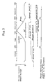
- step 106 the routine goes to step 106 in which, in order to correct the detection value of the pressure sensor 20a of No.1 cylinder to coincide with the detection level of the respective cylinders, the correction coefficient #1hos(%) is determined in accordance with the following equation: in which P(TDC) AVE is mean compression pressure of the respective cylinders which is obtained by making weighted mean of the cylinder pressures detected CTDC's of the respective cylinders. If the detection value of the pressure sensor 20a is multipled by the correction coefficient #1hos(%), the compression pressure detected by the pressure sensor 20a can be corrected so as to approach the mean level of the respective cylinders. That is, the variation characteristics (gradient) of the output signals of the pressure sensors 20a to 20d relative to the variation of the cylinder pressure can be corrected so as to essentially equal to each other for the respective cylinders, as shown in Fig. 8.
- a weighted mean of the current detected compression pressure #1P(TDC) and the preceding mean compression pressure P(TDC) AVE is derived in accordance with the following equation, and the result is used as a new mean compression pressure P(TDC) AVE .
- step 101 when it is not determined that the detected CTDC belongs to No.1 cylinder at step 101, the routine goes from step 101 to step 108 in which it is determined whether or not the detected CTDC belongs to No.2 cylinder.
- step 108 When it belongs to No.2 cylinder, a correction coefficient #2hos(%) for No.2 cylinder is derived at steps 109 to 114 which are similar processes to steps 102 to 107.
- step 108 When it is not determined that the detected CTDC belongs to No.2 cylinder at step 108, the routine goes from step 108 to step 115 in which it is determined whether or not the detected CTDC belongs to No.3 cylinder.
- step 115 When it belongs to No.3 cylinder, a correction coefficient #3hos(%) for No.3 cylinder is derived at steps 116 to 121 which are similar processes to steps 102 to 107.
- step 115 when it is not determined that the detected CTDC belongs to No.3 cylinder at step 115, the routine goes from step 115 to step 122. This means that the detected CTDC belongs No.4 cylinder.
- a correction coefficient #4hos(%) for No.4 cylinder is derived at steps 122 to 127 which are similar processes to steps 102 to 107.
- the dispersion of gradients of variations of the detection values of the respective pressure sensors 20a to 20d relative to the variation of the corresponding cylinder pressure can be corrected.
- this offset can not sufficiently corrected.
- the offset amounts of the detected values of the respective pressure sensors 20a to 20d are detected, and correction values ⁇ e corresponding to the respective offset amounts is set in accordance with a program of Fig. 5.
- the program shown in Fig. 5 is executed when a crank angle reference signal REF is produced in the intake stroke for the respective cylinders.
- a crank angle reference signal REF is produced in the intake stroke for the respective cylinders.
- the output voltages of the pressure sensors 20a to 20d essentially coincide with a zero voltage corresponding to the minimum reference value if it is normal. Therefore, if there is a difference between the output voltage of the pressure sensor 20a, 20b, 20c or 20d and the zero voltage in the intake stroke, this difference corresponds to the offset amount.
- step 201 it is determined whether or not the detected intake stroke belongs to No.1 cylinder.
- the routine goes to step 202 in which the A/D conversion value of the output voltage of the pressure sensor 20a is read so that the cylinder pressure #1P for No.1 cylinder is derived.
- an offset correction value ⁇ e1 for No.1 cylinder is derived in accordance with the following equation: ⁇ e1 ⁇ 0 - #1P
- the #1P should be zero while No.1 cylinder is in the intake stroke. Therefore, since the #1P corresponds to the offset error, the correction value corresponding to 0-#1P may be added to the detection value of the pressure sensor in order to compensate for the offset error.
- offset correction values ⁇ e2 to ⁇ e4 are derived from the differences between the zero level and the respective detected cylinder pressures in the intake strokes for the respective cylinders, at steps 204 to 211.
- Fig. 6 shows a process for correcting the detected values of the respective pressure sensors 20a to 20d, by using the correction coefficients #1hos to #4hos and the offset correction values ⁇ e1 to ⁇ e4.
- the program of Fig. 6 is executed at every predetermined fine crank angular position, e.g. every 8 o , of the crankshaft, which angular position is detected on the basis of a signal produced from the crank angle sensor 22.
- cylinder pressure data sampling for the respective cylinders are performed at every fine crank angle.
- this cylinder pressure data is used for deriving the mean effective pressure Pi in accordance with a program of Fig. 7.
- a counter value CNT is increased by 1.
- the counter value CNT is reset to zero at every output of the crank angle reference signal REF, i.e. at every 70 o BTDC position of the crankshaft in accordance with the program of Fig. 7.
- this cylinder discriminating value NCYL is set in sequence at every output of the crank angle reference signal REF in accordance with the program of Fig. 7.
- the cylinder discriminating value NCYL is set to be 1. Thereafter, it is held to be 1 until next crank angle reference signal REF corresponding to ignition timing of No.3 cylinder is output. Therefore, while the cylinder discriminating value NCYL is 1, data sampling of combustion pressure in No.1 cylinder can be performed by inputting the detected value of the pressure sensor 20a for No.1 cylinder.
- step 302 When it is determined that the cylinder discriminating value NCYL is 1 at step 302, the routine goes to step 303 in which A/D conversion of the output of the pressure sensor 20a for No.1 cylinder is performed, and the A/D conversion value is input.
- this input value (output voltage) is converted to cylinder pressure kg/cm2, and this conversion value is multiplied by the correction coefficient #1hos for No.1 cylinder to correct the output of the pressure sensor 20a.
- the offset correction value e1 is added to the result so that the cylinder pressure #1P(cnt) for No.1 cylinder can be accurately obtained.
- the counter value CNT is increased by 1 at every predetermined fine crank angular position, i.e. every 8 o , of the crankshaft, the sampling of the cylinder pressure #1P corrected by the correction coefficient #1hos and offsetting by the offset value ⁇ e1 is performed, and the number of the sampling is counted as a counter value CNT.
- the program of Fig. 7 is executed at every output of a crank angle reference signal REF from the crank angle sensor 22.
- the counter value CNT which is used for counting the number of samplings of the cylinder pressures #1P to #4P at every predetermined fine crank angle, is reset to zero.
- the routine goes to step 403 in which the cylinder discriminating value NCYL is set to be 1. Thereafter, the mean effective pressure Pi2 for No.2 cylinder is derived at step 404.
- the mean effective pressure Pi2 for No.2 cylinder is derived on the basis of the sampling value of the cylinder pressure #2P at step 404.
- step 404 After the mean effective pressure Pi2 is derived at step 404, the routine goes to step 413 in which the newest mean effective pressure Pi2 is set as the final mean effective pressure Pi.
- the cylinder discriminating value NCYL is set to be 3 at step 406, and then the mean effective pressure Pi1 for No.1 cylinder is derived at step 407. This means effective pressure Pi1 is set as the final mean effective pressure Pi at step 413.
- the cylinder discriminating value NCYL is set to be 4 at step 409, and then the mean effective pressure Pi3 for No.3 cylinder is derived at step 410.
- This mean effective pressure Pi3 is set as the final mean effective pressure Pi at step 413.
- the cylinder discriminating value NCYL is set to be 2 at step 411, and then the mean effective pressure Pi4 for No.4 cylinder is derived at step 412. This mean effective pressure Pi4 is set as the final mean effective pressure Pi at step 413.
- the mean effective pressure derived in the aforementioned manner can be used for the calculations of engine torque and surge torque which is fluctuation of the engine torque.
- various control such as setting the ignition timing and EGR ratio control, can be performed in accordance with the surge torque.
- the detection value of the cylinder pressure is corrected by using both the correction coefficients #1hos to #4hos and the offset values ⁇ e1 to ⁇ e4.
- the detection accuracy still can be improved as to the offset error with significant reduction or dispersion of the detection value produced between the respective cylinders.
Landscapes
- Engineering & Computer Science (AREA)
- Chemical & Material Sciences (AREA)
- Combustion & Propulsion (AREA)
- Physics & Mathematics (AREA)
- General Physics & Mathematics (AREA)
- Mechanical Engineering (AREA)
- General Engineering & Computer Science (AREA)
- Combined Controls Of Internal Combustion Engines (AREA)
- Measuring Fluid Pressure (AREA)
Applications Claiming Priority (2)
| Application Number | Priority Date | Filing Date | Title |
|---|---|---|---|
| JP196946/89 | 1989-07-31 | ||
| JP1196946A JPH0364653A (ja) | 1989-07-31 | 1989-07-31 | 内燃機関の筒内圧力検出装置 |
Publications (2)
| Publication Number | Publication Date |
|---|---|
| EP0411580A1 true EP0411580A1 (fr) | 1991-02-06 |
| EP0411580B1 EP0411580B1 (fr) | 1994-01-26 |
Family
ID=16366289
Family Applications (1)
| Application Number | Title | Priority Date | Filing Date |
|---|---|---|---|
| EP90114705A Expired - Lifetime EP0411580B1 (fr) | 1989-07-31 | 1990-07-31 | Système pour la détermination de pression dans le cylindre d'un moteur à combustion interne |
Country Status (4)
| Country | Link |
|---|---|
| US (1) | US5276625A (fr) |
| EP (1) | EP0411580B1 (fr) |
| JP (1) | JPH0364653A (fr) |
| DE (1) | DE69006287T2 (fr) |
Cited By (8)
| Publication number | Priority date | Publication date | Assignee | Title |
|---|---|---|---|---|
| WO2004022951A1 (fr) * | 2002-09-03 | 2004-03-18 | Robert Bosch Gmbh | Procede pour calibrer le systeme de detection des cylindres d'un moteur a combustion interne, notamment d'une automobile, dont les cylindres fonctionnent de façon individuelle |
| EP1593825A1 (fr) * | 2004-05-05 | 2005-11-09 | Ford Global Technologies, LLC, A subsidary of Ford Motor Company | Système pour équilibrer des cylindres dans un moteur à combustion interne avec un capteur par cylindre |
| FR2874054A1 (fr) * | 2004-08-04 | 2006-02-10 | Peugeot Citroen Automobiles Sa | Procede et systeme de supervision du calibrage d'une chaine d'acquisition de pression dans un cylindre d'un moteur diesel |
| WO2005108763A3 (fr) * | 2004-05-06 | 2006-04-20 | Ricardo Uk Ltd | Capteur de pression de cylindre |
| US7295917B2 (en) | 2004-10-26 | 2007-11-13 | Robert Bosch Gmbh | Method for determining a combustion chamber pressure |
| WO2007137912A1 (fr) * | 2006-05-29 | 2007-12-06 | Continental Automotive Gmbh | Procédé et dispositif pour faire fonctionner un moteur à combustion interne |
| FR2922261A1 (fr) * | 2007-10-11 | 2009-04-17 | Renault Sas | Systeme et procede de compensation de la derive d'un signal issu d'un capteur de pression cylindre |
| DE102015114949B4 (de) * | 2014-09-12 | 2017-07-13 | Denso Corporation | Zylinderdruckermittlungsvorrichtung |
Families Citing this family (29)
| Publication number | Priority date | Publication date | Assignee | Title |
|---|---|---|---|---|
| DE4109432A1 (de) * | 1991-03-22 | 1992-09-24 | Audi Ag | Klopfregelung einer fremdgezuendeten brennkraftmaschine |
| DE4402938A1 (de) * | 1994-02-01 | 1995-08-03 | Fev Motorentech Gmbh & Co Kg | Verfahren zur Steuerung eines Kolbenverbrennungsmotors unter Einhaltung der Laufgrenze |
| ITBO940248A1 (it) * | 1994-05-27 | 1995-11-27 | Weber Srl | Sistema per ridurre i fenomeni di detonazione in una camera di combustione in un motore endotermico. |
| JP2964210B2 (ja) * | 1994-06-14 | 1999-10-18 | 株式会社ユニシアジェックス | 筒内圧センサの診断装置 |
| JP3331789B2 (ja) * | 1994-11-29 | 2002-10-07 | トヨタ自動車株式会社 | 内燃機関の点火時期制御装置 |
| DE69631243T2 (de) * | 1995-10-02 | 2004-06-03 | Yamaha Hatsudoki K.K., Iwata | Verfahren zur Steuerung einer Brennkraftmaschine |
| WO1999061772A1 (fr) * | 1998-05-26 | 1999-12-02 | Caterpillar Inc. | Procede et dispositif de fenetrage programmable et collecte de donnees pour moteurs a combustion interne |
| US6516780B2 (en) * | 2000-11-13 | 2003-02-11 | Siemens Vdo Automotive Corporation | System and method for optimizing engine performance |
| US6557528B2 (en) | 2001-08-30 | 2003-05-06 | Caterpillar Inc. | Method of controlling detonation in an internal combustion engine |
| US6425372B1 (en) | 2001-08-30 | 2002-07-30 | Caterpillar Inc. | Method of controlling generation of nitrogen oxides in an internal combustion engine |
| US6609497B2 (en) | 2001-12-28 | 2003-08-26 | Visteon Global Technologies, Inc. | Method for determining MBT timing in an internal combustion engine |
| US6782737B2 (en) | 2002-04-08 | 2004-08-31 | Cummins, Inc. | System for estimating peak cylinder pressure in an internal combustion engine |
| JP4334959B2 (ja) * | 2003-09-19 | 2009-09-30 | 富士重工業株式会社 | 多気筒エンジンの燃焼圧データ収集システム |
| DE102004030258A1 (de) * | 2004-06-23 | 2005-09-01 | Audi Ag | Abgasrückführanordnung sowie Verfahren zum Betreiben einer Abgasrückführ-Anordnung |
| JP4440029B2 (ja) * | 2004-07-27 | 2010-03-24 | 三菱電機株式会社 | 内燃機関の制御装置 |
| DE102004048330B4 (de) * | 2004-10-05 | 2014-10-16 | Volkswagen Ag | Verfahren zur Diagnose für eine Motorsteuerung und entsprechende Motorsteuerung |
| US7751967B2 (en) * | 2006-04-12 | 2010-07-06 | Infineon Technologies Ag | Control systems and methods associated therewith |
| US7606655B2 (en) * | 2006-09-29 | 2009-10-20 | Delphi Technologies, Inc. | Cylinder-pressure-based electronic engine controller and method |
| KR100863545B1 (ko) * | 2007-03-22 | 2008-10-15 | 주식회사 만도 | 마스터실린더 압력센서 오프셋 보정방법 |
| ITTO20070589A1 (it) * | 2007-08-06 | 2009-02-07 | Global Technology Operations I | Sistema di monitoraggio della pressione |
| US8260531B2 (en) * | 2008-11-19 | 2012-09-04 | Toyota Jidosha Kabushiki Kaisha | Abnormality detection device for in-cylinder pressure sensor, abnormality detection method for in-cylinder pressure sensor and control apparatus for internal combustion engine |
| WO2012104994A1 (fr) * | 2011-02-01 | 2012-08-09 | トヨタ自動車株式会社 | Dispositif de commande pour moteur à combustion interne |
| DE102011089370A1 (de) * | 2011-12-21 | 2013-06-27 | Robert Bosch Gmbh | Verfahren und Vorrichtung zum Betreiben einer Kaltstart-Emissions-Steuerung einer Brennkraftmaschine |
| JP5836114B2 (ja) * | 2011-12-28 | 2015-12-24 | 三菱重工業株式会社 | ガスエンジンの燃焼制御装置 |
| JP5561283B2 (ja) * | 2012-01-11 | 2014-07-30 | 株式会社デンソー | センサ信号の処理装置 |
| US9279406B2 (en) | 2012-06-22 | 2016-03-08 | Illinois Tool Works, Inc. | System and method for analyzing carbon build up in an engine |
| DE102014007009B4 (de) * | 2014-05-13 | 2018-01-18 | Mtu Friedrichshafen Gmbh | Motorüberwachung mittels zylinderindividueller Drucksensoren vorzüglich bei Magergasmotoren mit gespülter Vorkammer |
| US9435277B2 (en) * | 2014-07-29 | 2016-09-06 | Freescale Semiconductor, Inc. | Method of calibrating a crank angle of a combustion engine |
| US20160160776A1 (en) * | 2014-12-08 | 2016-06-09 | Caterpillar Inc. | Engine System and Method |
Citations (3)
| Publication number | Priority date | Publication date | Assignee | Title |
|---|---|---|---|---|
| EP0145480A2 (fr) * | 1983-12-15 | 1985-06-19 | Texas Instruments Incorporated | Transmetteur de la pression d'un cylindre d'un moteur à combustion interne |
| US4596217A (en) * | 1983-04-12 | 1986-06-24 | Robert Bosch Gmbh | Method and system to prevent knocking operation of an internal combustion engine |
| DE3641114A1 (de) * | 1985-12-02 | 1987-06-04 | Honda Motor Co Ltd | Verfahren zur zylinderdruckdetektion bei einer brennkraftmaschine |
Family Cites Families (14)
| Publication number | Priority date | Publication date | Assignee | Title |
|---|---|---|---|---|
| JPS55138101A (en) * | 1979-04-13 | 1980-10-28 | Hitachi Ltd | Engine controller |
| US4383431A (en) * | 1980-11-03 | 1983-05-17 | The Perkin-Elmer Corporation | Auto-zero system for pressure transducers |
| US4547859A (en) * | 1981-05-11 | 1985-10-15 | S & W Instruments, Inc. | Methods for scaling and calibrating predetermined signals |
| US4660435A (en) * | 1981-05-26 | 1987-04-28 | Rockwell International Corporation | Fiber composite flywheel rim |
| JPS59206648A (ja) * | 1983-01-26 | 1984-11-22 | Nissan Motor Co Ltd | 内燃機関の燃焼室内圧力を検出するセンサの較正方法 |
| EP0115806A3 (fr) * | 1983-01-26 | 1986-03-05 | Nissan Motor Co., Ltd. | Dispositif de commande pour moteur à combustion interne |
| US4620438A (en) * | 1983-12-15 | 1986-11-04 | Texas Instruments Incorporated | Cylinder pressure transmitter for an internal combustion engine |
| US4767960A (en) * | 1983-12-15 | 1988-08-30 | Texas Instruments Incorporated | Cylinder pressure transmitter for an internal combustion engine |
| JPS6212827A (ja) * | 1985-07-10 | 1987-01-21 | Hitachi Ltd | エンジンの燃焼圧検出装置 |
| JPS62192627A (ja) * | 1986-02-19 | 1987-08-24 | Honda Motor Co Ltd | 内燃機関の気筒内圧力の補正方法 |
| US4817022A (en) * | 1986-07-30 | 1989-03-28 | Barber-Colman Company | Method and apparatus for automatic offset compensation in parameter-sensing transducer systems |
| US4711215A (en) * | 1986-10-27 | 1987-12-08 | General Motors Corporation | LPP combustion control for IC engine with abnormal combustion |
| JPH01262348A (ja) * | 1988-04-13 | 1989-10-19 | Mitsubishi Electric Corp | 内燃機関の制御装置 |
| DE58903237D1 (de) * | 1989-05-23 | 1993-02-18 | Siemens Ag | Verfahren zur bestimmung des brennraumdruckes in einem zylinder einer brennkraftmaschine mit einem drucksensor. |
-
1989
- 1989-07-31 JP JP1196946A patent/JPH0364653A/ja active Pending
-
1990
- 1990-07-31 DE DE69006287T patent/DE69006287T2/de not_active Expired - Fee Related
- 1990-07-31 US US07/559,943 patent/US5276625A/en not_active Expired - Fee Related
- 1990-07-31 EP EP90114705A patent/EP0411580B1/fr not_active Expired - Lifetime
Patent Citations (3)
| Publication number | Priority date | Publication date | Assignee | Title |
|---|---|---|---|---|
| US4596217A (en) * | 1983-04-12 | 1986-06-24 | Robert Bosch Gmbh | Method and system to prevent knocking operation of an internal combustion engine |
| EP0145480A2 (fr) * | 1983-12-15 | 1985-06-19 | Texas Instruments Incorporated | Transmetteur de la pression d'un cylindre d'un moteur à combustion interne |
| DE3641114A1 (de) * | 1985-12-02 | 1987-06-04 | Honda Motor Co Ltd | Verfahren zur zylinderdruckdetektion bei einer brennkraftmaschine |
Cited By (12)
| Publication number | Priority date | Publication date | Assignee | Title |
|---|---|---|---|---|
| WO2004022951A1 (fr) * | 2002-09-03 | 2004-03-18 | Robert Bosch Gmbh | Procede pour calibrer le systeme de detection des cylindres d'un moteur a combustion interne, notamment d'une automobile, dont les cylindres fonctionnent de façon individuelle |
| US7260470B2 (en) | 2002-09-03 | 2007-08-21 | Robert Bosch Gmbh | Method for calibration of the cylinder sensors suite on an internal combustion engine with individual cylinder operation in particular in a motor vehicle |
| CN100371574C (zh) * | 2002-09-03 | 2008-02-27 | 罗伯特-博希股份公司 | 汽车的气缸单独运转式内燃机的气缸传感器的校准方法 |
| EP1593825A1 (fr) * | 2004-05-05 | 2005-11-09 | Ford Global Technologies, LLC, A subsidary of Ford Motor Company | Système pour équilibrer des cylindres dans un moteur à combustion interne avec un capteur par cylindre |
| WO2005108763A3 (fr) * | 2004-05-06 | 2006-04-20 | Ricardo Uk Ltd | Capteur de pression de cylindre |
| FR2874054A1 (fr) * | 2004-08-04 | 2006-02-10 | Peugeot Citroen Automobiles Sa | Procede et systeme de supervision du calibrage d'une chaine d'acquisition de pression dans un cylindre d'un moteur diesel |
| EP1624170A3 (fr) * | 2004-08-04 | 2010-10-06 | Peugeot Citroën Automobiles SA | Procédé et système de supervision du calibrage d'une chaîne d'acquisition de pression dans un cylindre d'un moteur. |
| US7295917B2 (en) | 2004-10-26 | 2007-11-13 | Robert Bosch Gmbh | Method for determining a combustion chamber pressure |
| WO2007137912A1 (fr) * | 2006-05-29 | 2007-12-06 | Continental Automotive Gmbh | Procédé et dispositif pour faire fonctionner un moteur à combustion interne |
| US7853393B2 (en) | 2006-05-29 | 2010-12-14 | Continental Automotive Gmbh | Method and device for operating an internal combustion engine |
| FR2922261A1 (fr) * | 2007-10-11 | 2009-04-17 | Renault Sas | Systeme et procede de compensation de la derive d'un signal issu d'un capteur de pression cylindre |
| DE102015114949B4 (de) * | 2014-09-12 | 2017-07-13 | Denso Corporation | Zylinderdruckermittlungsvorrichtung |
Also Published As
| Publication number | Publication date |
|---|---|
| DE69006287T2 (de) | 1994-06-16 |
| US5276625A (en) | 1994-01-04 |
| JPH0364653A (ja) | 1991-03-20 |
| DE69006287D1 (de) | 1994-03-10 |
| EP0411580B1 (fr) | 1994-01-26 |
Similar Documents
| Publication | Publication Date | Title |
|---|---|---|
| EP0411580A1 (fr) | Système pour la détermination de pression dans le cylindre d'un moteur à combustion interne | |
| AU750684B2 (en) | Process for detecting a misfire in an internal combustion engine and system for carrying out said process | |
| US7347081B2 (en) | Knock detecting apparatus and method for internal combustion engine | |
| US7909018B2 (en) | Control for determining a firing timing of an internal-combustion engine | |
| US4562818A (en) | Method and apparatus for controlling the air-fuel ratio in an internal combustion engine | |
| EP0115806A2 (fr) | Dispositif de commande pour moteur à combustion interne | |
| US4531399A (en) | Method of calibrating pressure sensor | |
| EP0657729A2 (fr) | Appareil et méthode autodiagnostic pour déterminer l'occurence d'un oléfant dans un capteur sensible à la pression interne d'un cylindre, utilisable dans un système de détection ou de contrôle de la combustion dans un moteur | |
| US5265575A (en) | Apparatus for controlling internal combustion engine | |
| CA2428049A1 (fr) | Procede de commande d'un moteur a combustion interne | |
| EP0115807B1 (fr) | Méthode de discrimination des pressions de combustion pour moteur à combustion interne | |
| KR930008806B1 (ko) | 엔진의 점화시기 제어장치 | |
| EP0490392B1 (fr) | Dispositif pour commander le couple d'un moteur à combustion interne | |
| EP0443650B1 (fr) | Méthode et dispositif d'évaluation de la masse d'air dans un moteur deux temps à balayage du carter de vilebrequin | |
| JPH07119530A (ja) | 内燃機関の燃焼状態検出装置 | |
| US5571958A (en) | Apparatus and method for detecting misfire in an internal combustion engine | |
| CA2525020C (fr) | Capteur d'etat de combustion pour moteur | |
| EP1593825B1 (fr) | Système pour équilibrer des cylindres dans un moteur à combustion interne avec un capteur par cylindre | |
| EP1439299A1 (fr) | Dispositif de commande de moteur | |
| JPH07310585A (ja) | 筒内圧センサの診断装置 | |
| JPH11193743A (ja) | エンジンの筒内圧検出装置 | |
| JPH07119532A (ja) | 内燃機関の失火検出装置 | |
| JPH09195844A (ja) | 内燃機関の筒内圧検出装置 | |
| JPH09133042A (ja) | 内燃機関の筒内圧検出装置 | |
| JP2964435B2 (ja) | 内燃機関の燃焼状態検出装置 |
Legal Events
| Date | Code | Title | Description |
|---|---|---|---|
| PUAI | Public reference made under article 153(3) epc to a published international application that has entered the european phase |
Free format text: ORIGINAL CODE: 0009012 |
|
| 17P | Request for examination filed |
Effective date: 19901214 |
|
| AK | Designated contracting states |
Kind code of ref document: A1 Designated state(s): DE GB |
|
| 17Q | First examination report despatched |
Effective date: 19920216 |
|
| GRAA | (expected) grant |
Free format text: ORIGINAL CODE: 0009210 |
|
| AK | Designated contracting states |
Kind code of ref document: B1 Designated state(s): DE GB |
|
| REF | Corresponds to: |
Ref document number: 69006287 Country of ref document: DE Date of ref document: 19940310 |
|
| PLBE | No opposition filed within time limit |
Free format text: ORIGINAL CODE: 0009261 |
|
| STAA | Information on the status of an ep patent application or granted ep patent |
Free format text: STATUS: NO OPPOSITION FILED WITHIN TIME LIMIT |
|
| 26N | No opposition filed | ||
| PGFP | Annual fee paid to national office [announced via postgrant information from national office to epo] |
Ref country code: GB Payment date: 19980722 Year of fee payment: 9 |
|
| PGFP | Annual fee paid to national office [announced via postgrant information from national office to epo] |
Ref country code: DE Payment date: 19980810 Year of fee payment: 9 |
|
| PG25 | Lapsed in a contracting state [announced via postgrant information from national office to epo] |
Ref country code: GB Free format text: LAPSE BECAUSE OF NON-PAYMENT OF DUE FEES Effective date: 19990731 |
|
| GBPC | Gb: european patent ceased through non-payment of renewal fee |
Effective date: 19990731 |
|
| PG25 | Lapsed in a contracting state [announced via postgrant information from national office to epo] |
Ref country code: DE Free format text: LAPSE BECAUSE OF NON-PAYMENT OF DUE FEES Effective date: 20000503 |