EP0411608A2 - Steuervorrichtung für Kraftfahrzeugwechselstromgenerator - Google Patents
Steuervorrichtung für Kraftfahrzeugwechselstromgenerator Download PDFInfo
- Publication number
- EP0411608A2 EP0411608A2 EP90114766A EP90114766A EP0411608A2 EP 0411608 A2 EP0411608 A2 EP 0411608A2 EP 90114766 A EP90114766 A EP 90114766A EP 90114766 A EP90114766 A EP 90114766A EP 0411608 A2 EP0411608 A2 EP 0411608A2
- Authority
- EP
- European Patent Office
- Prior art keywords
- voltage
- generator
- control device
- vehicle
- battery
- Prior art date
- Legal status (The legal status is an assumption and is not a legal conclusion. Google has not performed a legal analysis and makes no representation as to the accuracy of the status listed.)
- Withdrawn
Links
Images


Classifications
-
- H—ELECTRICITY
- H02—GENERATION; CONVERSION OR DISTRIBUTION OF ELECTRIC POWER
- H02J—ELECTRIC POWER NETWORKS; CIRCUIT ARRANGEMENTS OR SYSTEMS FOR SUPPLYING OR DISTRIBUTING ELECTRIC POWER; SYSTEMS FOR STORING ELECTRIC ENERGY
- H02J7/00—Circuit arrangements for charging or discharging batteries or for supplying loads from batteries
- H02J7/14—Circuit arrangements for charging or discharging batteries or for supplying loads from batteries for charging batteries from dynamo-electric generators driven at varying speed, e.g. on vehicle
- H02J7/16—Regulation of the charging current or voltage by variation of field
- H02J7/24—Regulation of the charging current or voltage by variation of field using discharge tubes or semiconductor devices
- H02J7/243—Regulation of the charging current or voltage by variation of field using discharge tubes or semiconductor devices with on/off action
-
- Y—GENERAL TAGGING OF NEW TECHNOLOGICAL DEVELOPMENTS; GENERAL TAGGING OF CROSS-SECTIONAL TECHNOLOGIES SPANNING OVER SEVERAL SECTIONS OF THE IPC; TECHNICAL SUBJECTS COVERED BY FORMER USPC CROSS-REFERENCE ART COLLECTIONS [XRACs] AND DIGESTS
- Y02—TECHNOLOGIES OR APPLICATIONS FOR MITIGATION OR ADAPTATION AGAINST CLIMATE CHANGE
- Y02T—CLIMATE CHANGE MITIGATION TECHNOLOGIES RELATED TO TRANSPORTATION
- Y02T10/00—Road transport of goods or passengers
- Y02T10/60—Other road transportation technologies with climate change mitigation effect
- Y02T10/70—Energy storage systems for electromobility, e.g. batteries
Definitions
- This invention relates to a control device for a vehicle AC generator, and more particularly to a control device for a vehicle AC generator large in capacity which can stably control the battery charging voltage (hereinafter referred to as "a vehicle AC generator control device", when applicable).
- a vehicle AC generator control device a control device for a vehicle AC generator large in capacity which can stably control the battery charging voltage
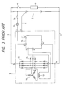
- Fig. 3 is a wiring diagram for a description of the battery charging operation of a conventional vehicle AC generator control device.
- reference numeral 1 designates an AC generator mounted on a vehicle and driven by an engine, which comprises: an armature coil 11 generating three-phase AC voltage; a field coil 12; a main rectifier 13 including neutral point diodes for full-wave rectifying the three-phase output of the armature coil 11; an auxiliary rectifier 14 for splitting the output of the main rectifier 13 to mainly supply field current; and a regulator 15 built in the AC generator 1 to regulate the system voltage to a predetermined value.
- reference numeral 2 designates a battery; 3, a vehicle electric load; 4, a load switch; 5, a key switch; and 6, a generation indicating lamp.
- reference character (a) designates a charging line connected between output terminal B of the AC generator 1 and the battery 2; (b), a grounding line connected between grounding terminal E1 of the AC generator 1 and the battery 2; and (c), a first detecting line for detecting the system voltage using the regulator 15.
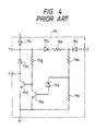
- Fig. 4 is an electrical circuit diagram of the regulator 15 shown in Fig. 3.
- reference characters 15a and 15b designate voltage dividing resistors for dividing through a diode 15c the system voltage which is applied to terminals S and S′; 15d, a Zener diode connected to the voltage division point (or connecting point) of the voltage dividing resistors 15a and 15b, these elements 15a through 15d detecting the system voltage.
- reference characters 15a and 15b designate voltage dividing resistors for dividing through a diode 15c the system voltage which is applied to terminals S and S′; 15d, a Zener diode connected to the voltage division point (or connecting point) of the voltage dividing resistors 15a and 15b, these elements 15a through 15d detecting the system voltage.
- reference character 15e designates a drive transistor which is driven when the Zener diode 15d is rendered conductive; 15f, a power transistor driven by the drive transistor 15e; 15g, a resistor connected to the base of the power transistor 15f; 15h, a diode for absorbing the serge voltage induced when the power transistor 15f is rendered non-conductive; and 15i, a reverse current preventing diode.
- the output terminal of the auxiliary rectifier 14 is connected through a diode 15j and a resistor 15k to the voltage dividing resistors 15a and 15b, so that, when it becomes impossible to detect the system voltage for instance because the first detecting line (c) is disconnected, the output voltage of the auxiliary rectifier 14 is detected to prevent the occurrence of the difficulty that the system voltage comes out of control.
- the system voltage is applied through the positive terminal of the battery 2 and the first detecting line (c) to the external terminal S of the AC generator 1 and to the external terminal S′ of the regulator 15. Therefore, the system voltage is applied through the diode 15C to the voltage dividing resistors 15a and 15b so as to be detected by the latter 15a and 15b.
- the voltage at the voltage division point of the voltage dividing resistors 15a and 15b exceeds the Zener voltage of the Zener diode 15d as the system voltages increases, the drive transistor 15e is rendered conductive, and the power transistor 15f is therefore rendered rendered non-conductive.
- the drive transistor 15e is rendered non-conductive, and the power transistor 15f is therefore rendered conductive. That is, the power transistor 15f is rendered non-conductive or conductive respectively in response to the rise or fall of the system voltage, so that the field current applied to the field coil 13 is controlled in an on and off mode, whereby the system voltage is maintained constant.
- the output voltage of the auxiliary rectifier 14 is applied through the diode 15j and the resistor 15k to the voltage dividing resistors 15a and 15b, as a result of which the voltage control is made with a regulating voltage slightly higher than the normal regulating voltage.
- the control device With the control device thus constructed, the system voltage is detected through the first detecting line (c) from the positive terminal of the battery 2, and therefore the voltage drop caused by the resistance of the charging line (a) can be compensated.
- the control device is considerably effective in stabilization of the battery charging voltage.
- the ground potential of the regulator 15 is the ground terminal potential of the AC generator 1
- the voltage drop caused by the resistance of the grounding line (b) cannot be compensated.
- the battery charging voltage is decreased (the line (a) in Fig. 5). Because of the decrease ( ⁇ E in Fig. 5), the battery is not sufficiently charged depending on the frequency of use of the vehicle electric load 4, and the service life of the battery may be shortened. That is, the charging system is low in reliability.
- vehicle electrical loads tend to increase, thus requiring generators larger in capacity, and increasing the above-described decrease ⁇ E as much. Hence, this problem cannot be disregarded.
- the output of the auxiliary rectifier 14 includes plenty of rectification ripple components, so that the control device is lacking in the stability of control.
- an object of this invention is to eliminate the above-described difficulties accompanying a conventional vehicle AC generator control device. More specifically, an object of the invention is to provide a vehicle AC generator control device in which it is possible to prevent the battery charging voltage from decreasing by the resistance of the grounding line in the charging system even when the generator output increases, and erroneous control due to ripples is prevented.
- a vehicle AC generator control device has a regulator which comprises: voltage detecting means for detecting the system voltage of a charging system including an AC generator, a battery, and a vehicle electrical load; and drive means for driving a switching element connected in series to the field coil of the generator, the voltage detecting means having a grounding terminal which is connected to the negative terminal of the battery.
- the detection signal of the voltage detecting means is transferred to the drive means by isolated transfer means.
- the voltage detecting means has a detecting line on the grounding side, so as to compensate the voltage drop caused by the resistance of the grounding line, thereby to minimize the variation of the battery charging voltage which is caused by the variation of the generator output.
- the isolated transfer means eliminates the erroneous control of the voltage detecting means which is caused by the rectification ripple ccmponent of the auxiliary rectifier, thus providing a stable control operation.
- Fig. 1 is a circuit diagram, partly as a block diagram, for a description of the charging operation of the control device according to the invention.
- the control circuit is different from the above-described conventional one in that a ground potential detecting terminal E2′ is provided as an external terminal of a regulator 15, and the terminal E2′ is connected through an external terminal E2 of the AC generator 1 and a second detecting line (d) to the negative terminal of the battery 2.
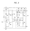
- Fig. 2 is a circuit diagram showing the arrangement of the regulator 15 in more detail.
- the regulator 15 is made up of voltage detecting means 151, drive means 152, and isolated transfer means, namely, a photo-coupler (15m and 15n) provided between the two means 151 and 152.
- reference character 15l designates a detecting transistor which is driven when a Zener diode 15d is rendered conductive
- 15m and 15n the aforementioned photo-coupler made up of a light emitting diode 15m and a light-sensitive transistor 15n to transfer the detection signal of the detecting transistor 15l to the drive transistor 15e
- 15o and 15p current limiting resistors for determining the drive currents of the light emitting diode 15m and the light-sensitive transistor 15n
- 15q a diode which, when the first detecting line (c) is disconnected, obtains drive current for the light emitting diode 15m from the output of the auxiliary rectifier 14.
- the voltage detecting means 151 is connected to the drive means 152 for instance by directly connecting the collector of the detecting transistor 15l to the base of the power transistor 15f.
- the method is disadvantageous in that, because of the potential difference between the ground potentials E1′ and E2′ (E1′ ⁇ E2′ with the increasing output current), the drive means 152 may operate erroneously.
- the output of the auxiliary rectifier 14 is more in rectification ripple component than that of the main rectifier 13 connected to the battery 2.
- the isolated transfer means is provided which is the photo-coupler made up of the light emitting diode 15m and the light-sensitive transistor 15n.
- the control device When the engine starts, the AC generator 1 starts power generation, and the system voltage is applied through the detecting lines (c) and (d) to the regulator 15. In the regulator 15, the system voltage is applied through the diode 15c to the voltage dividing resistors 15a and 15b so as to be detected with the aid of the Zener diode 15d. When the system voltage increases, and the voltage at the voltage division point of the voltage dividing resistors 15a and 15b exceeds the Zener voltage of the Zener diode 15d, then the detecting transistor 15l is rendered conductive, and the light emitting diode 15m is rendered conductive (operated).
- the light-sensitive transistor 15n is rendered conductive by light transfer, and therefore the drive transistor 15e is rendered conductive, so that the power transistor 15f is rendered non-conductive.
- the system voltage decreases, and the voltage at the voltage division point becomes the Zener voltage or lower, then the detecting transistor 15l is rendered non-conductive, and the light emitting diode 15m is also rendered non-conductive.
- the light-sensitive transistor 15n and the drive transistor 15e are both rendered non-conductive, and the power transistor 15e is rendered conductive.
- the power transistor 15f is rendered conductive or non-conductive; that is, the field current is controlled, whereby the system voltage is regulated to a predetermined value.
- the ground terminal E2′ of the voltage detecting circuit i.e. the ground terminal of the voltage dividing resistor 15b and the emitter of the detecting transistor 15l
- the voltage drop of the charging line (a) caused by the first detecting line (c) is compensated, and the voltage drop of the grounding line (b) is also compensated. Therefore, the battery charging voltage can be controlled substantially constant even if the output of the generator changes.
- the photo-coupler is employed as the isolated transfer means; however, the same effect can be obtained by replacing it with other isolated transfer means.
Landscapes
- Engineering & Computer Science (AREA)
- Power Engineering (AREA)
- Control Of Charge By Means Of Generators (AREA)
- Control Of Eletrric Generators (AREA)
Applications Claiming Priority (2)
| Application Number | Priority Date | Filing Date | Title |
|---|---|---|---|
| JP200532/89 | 1989-08-01 | ||
| JP1200532A JPH0365028A (ja) | 1989-08-01 | 1989-08-01 | 車両用交流発電機の制御装置 |
Publications (2)
| Publication Number | Publication Date |
|---|---|
| EP0411608A2 true EP0411608A2 (de) | 1991-02-06 |
| EP0411608A3 EP0411608A3 (en) | 1992-03-25 |
Family
ID=16425873
Family Applications (1)
| Application Number | Title | Priority Date | Filing Date |
|---|---|---|---|
| EP19900114766 Withdrawn EP0411608A3 (en) | 1989-08-01 | 1990-08-01 | Control device for vehicle ac generator |
Country Status (2)
| Country | Link |
|---|---|
| EP (1) | EP0411608A3 (de) |
| JP (1) | JPH0365028A (de) |
Families Citing this family (2)
| Publication number | Priority date | Publication date | Assignee | Title |
|---|---|---|---|---|
| JP2008133839A (ja) * | 2006-11-27 | 2008-06-12 | Nsk Warner Kk | 発進クラッチ |
| JP4880434B2 (ja) * | 2006-12-04 | 2012-02-22 | Nskワーナー株式会社 | 発進クラッチ |
Family Cites Families (2)
| Publication number | Priority date | Publication date | Assignee | Title |
|---|---|---|---|---|
| US4224562A (en) * | 1978-02-27 | 1980-09-23 | Sure Power Products, Inc. | Voltage regulator with electrically isolated output stage |
| JPS6022500A (ja) * | 1983-07-15 | 1985-02-04 | Mitsubishi Electric Corp | 充電発電機の制御装置 |
-
1989
- 1989-08-01 JP JP1200532A patent/JPH0365028A/ja active Pending
-
1990
- 1990-08-01 EP EP19900114766 patent/EP0411608A3/en not_active Withdrawn
Also Published As
| Publication number | Publication date |
|---|---|
| JPH0365028A (ja) | 1991-03-20 |
| EP0411608A3 (en) | 1992-03-25 |
Similar Documents
| Publication | Publication Date | Title |
|---|---|---|
| US4491779A (en) | Motor vehicle electrical system | |
| EP0795947A2 (de) | Stromversorgungseinheit für Fahrzeuge | |
| US6344734B1 (en) | Controller of AC generator for use in vehicles | |
| EP0118779B1 (de) | Spannungsregler für einen Ladegenerator | |
| US5266882A (en) | Control device for an alternating current generator of a vehicle | |
| US4658200A (en) | Protection circuit for voltage regulator of vehicle mounted generator | |
| US3942096A (en) | Voltage regulating system | |
| EP0408059A2 (de) | Steuergerät für einen Fahrzeugwechselstromgenerator | |
| US4594631A (en) | Temperature protective circuit for a charging generator | |
| US4365241A (en) | Device for indicating the charging state of a battery | |
| US4295087A (en) | Charge indicator circuit for a battery charging system | |
| EP0178395B1 (de) | Generatorspannungsregler | |
| EP0289608B1 (de) | Gleichstromdynamo für fahrzeuge | |
| US4471287A (en) | Charging generator control apparatus | |
| JPH08294239A (ja) | 電圧調整回路 | |
| US4525662A (en) | Battery charging control system for automobile | |
| HK1000928B (en) | Ac generator for vehicles | |
| US4276577A (en) | Motor vehicle battery charging installation | |
| US4222005A (en) | Testing device for generator output voltage regulators | |
| US4280087A (en) | Voltage regulator | |
| EP0411608A2 (de) | Steuervorrichtung für Kraftfahrzeugwechselstromgenerator | |
| US4755734A (en) | Voltage regulator for vehicle mounted generator | |
| US4079306A (en) | Current generating system for motor vehicle | |
| EP1705794A2 (de) | Spannungsregelungssystem für einen Fahrzeuggenerator | |
| US4470004A (en) | Charge indicating system |
Legal Events
| Date | Code | Title | Description |
|---|---|---|---|
| PUAI | Public reference made under article 153(3) epc to a published international application that has entered the european phase |
Free format text: ORIGINAL CODE: 0009012 |
|
| AK | Designated contracting states |
Kind code of ref document: A2 Designated state(s): DE FR GB |
|
| 17P | Request for examination filed |
Effective date: 19901220 |
|
| PUAL | Search report despatched |
Free format text: ORIGINAL CODE: 0009013 |
|
| AK | Designated contracting states |
Kind code of ref document: A3 Designated state(s): DE FR GB |
|
| 17Q | First examination report despatched |
Effective date: 19931220 |
|
| STAA | Information on the status of an ep patent application or granted ep patent |
Free format text: STATUS: THE APPLICATION IS DEEMED TO BE WITHDRAWN |
|
| 18D | Application deemed to be withdrawn |
Effective date: 19940503 |