EP0411689B1 - Verfahren zur kontinuierlichen Kontrolle der Funktionstüchtigkeit von unterirdischen metallischen Strukturen und Vorrichtungen zu seiner Realisierung - Google Patents
Verfahren zur kontinuierlichen Kontrolle der Funktionstüchtigkeit von unterirdischen metallischen Strukturen und Vorrichtungen zu seiner Realisierung Download PDFInfo
- Publication number
- EP0411689B1 EP0411689B1 EP90201949A EP90201949A EP0411689B1 EP 0411689 B1 EP0411689 B1 EP 0411689B1 EP 90201949 A EP90201949 A EP 90201949A EP 90201949 A EP90201949 A EP 90201949A EP 0411689 B1 EP0411689 B1 EP 0411689B1
- Authority
- EP
- European Patent Office
- Prior art keywords
- current
- modulation
- monitoring
- soundness
- covering
- Prior art date
- Legal status (The legal status is an assumption and is not a legal conclusion. Google has not performed a legal analysis and makes no representation as to the accuracy of the status listed.)
- Expired - Lifetime
Links
- 238000000034 method Methods 0.000 title claims description 26
- 239000002184 metal Substances 0.000 title claims description 18
- 238000012544 monitoring process Methods 0.000 title claims description 11
- 230000001681 protective effect Effects 0.000 title claims 8
- 238000004210 cathodic protection Methods 0.000 claims description 21
- 238000005259 measurement Methods 0.000 claims description 16
- 239000012530 fluid Substances 0.000 claims description 4
- 238000009413 insulation Methods 0.000 description 12
- 230000007547 defect Effects 0.000 description 10
- 238000010586 diagram Methods 0.000 description 9
- 230000007797 corrosion Effects 0.000 description 7
- 238000005260 corrosion Methods 0.000 description 7
- 239000000463 material Substances 0.000 description 7
- 229910000831 Steel Inorganic materials 0.000 description 5
- 239000010959 steel Substances 0.000 description 5
- 238000012360 testing method Methods 0.000 description 5
- 230000008859 change Effects 0.000 description 4
- 238000000576 coating method Methods 0.000 description 4
- 230000000694 effects Effects 0.000 description 4
- XLYOFNOQVPJJNP-UHFFFAOYSA-N water Substances O XLYOFNOQVPJJNP-UHFFFAOYSA-N 0.000 description 4
- 239000011248 coating agent Substances 0.000 description 3
- 238000003487 electrochemical reaction Methods 0.000 description 3
- 230000002787 reinforcement Effects 0.000 description 3
- 239000004215 Carbon black (E152) Substances 0.000 description 2
- 239000004698 Polyethylene Substances 0.000 description 2
- 230000009471 action Effects 0.000 description 2
- 230000005540 biological transmission Effects 0.000 description 2
- 239000013626 chemical specie Substances 0.000 description 2
- 238000010276 construction Methods 0.000 description 2
- 230000002596 correlated effect Effects 0.000 description 2
- 230000000875 corresponding effect Effects 0.000 description 2
- 238000004512 die casting Methods 0.000 description 2
- 239000002657 fibrous material Substances 0.000 description 2
- 239000007789 gas Substances 0.000 description 2
- 229930195733 hydrocarbon Natural products 0.000 description 2
- 150000002430 hydrocarbons Chemical class 0.000 description 2
- 238000007689 inspection Methods 0.000 description 2
- 238000009434 installation Methods 0.000 description 2
- 239000003921 oil Substances 0.000 description 2
- 230000035699 permeability Effects 0.000 description 2
- -1 polyethylene Polymers 0.000 description 2
- 229920000573 polyethylene Polymers 0.000 description 2
- 239000002861 polymer material Substances 0.000 description 2
- 230000004044 response Effects 0.000 description 2
- 238000012795 verification Methods 0.000 description 2
- OKTJSMMVPCPJKN-UHFFFAOYSA-N Carbon Chemical compound [C] OKTJSMMVPCPJKN-UHFFFAOYSA-N 0.000 description 1
- CWYNVVGOOAEACU-UHFFFAOYSA-N Fe2+ Chemical compound [Fe+2] CWYNVVGOOAEACU-UHFFFAOYSA-N 0.000 description 1
- 239000010425 asbestos Substances 0.000 description 1
- 239000010426 asphalt Substances 0.000 description 1
- QVGXLLKOCUKJST-UHFFFAOYSA-N atomic oxygen Chemical compound [O] QVGXLLKOCUKJST-UHFFFAOYSA-N 0.000 description 1
- 239000006229 carbon black Substances 0.000 description 1
- 230000000295 complement effect Effects 0.000 description 1
- 239000004020 conductor Substances 0.000 description 1
- 238000001514 detection method Methods 0.000 description 1
- 230000006866 deterioration Effects 0.000 description 1
- 238000009826 distribution Methods 0.000 description 1
- 230000005684 electric field Effects 0.000 description 1
- 150000002118 epoxides Chemical class 0.000 description 1
- 230000002349 favourable effect Effects 0.000 description 1
- 239000011152 fibreglass Substances 0.000 description 1
- 239000000446 fuel Substances 0.000 description 1
- 239000010439 graphite Substances 0.000 description 1
- 229910002804 graphite Inorganic materials 0.000 description 1
- 150000002500 ions Chemical class 0.000 description 1
- 239000007788 liquid Substances 0.000 description 1
- 238000012806 monitoring device Methods 0.000 description 1
- 229910052760 oxygen Inorganic materials 0.000 description 1
- 239000001301 oxygen Substances 0.000 description 1
- 239000000123 paper Substances 0.000 description 1
- 229920000642 polymer Polymers 0.000 description 1
- 229920000915 polyvinyl chloride Polymers 0.000 description 1
- 239000004800 polyvinyl chloride Substances 0.000 description 1
- 238000002360 preparation method Methods 0.000 description 1
- 230000003449 preventive effect Effects 0.000 description 1
- 230000000750 progressive effect Effects 0.000 description 1
- 239000011253 protective coating Substances 0.000 description 1
- 239000011241 protective layer Substances 0.000 description 1
- 230000009467 reduction Effects 0.000 description 1
- 229910052895 riebeckite Inorganic materials 0.000 description 1
- 238000005070 sampling Methods 0.000 description 1
- 230000035945 sensitivity Effects 0.000 description 1
- 238000000926 separation method Methods 0.000 description 1
- 238000003860 storage Methods 0.000 description 1
- 239000000126 substance Substances 0.000 description 1
- 229920001059 synthetic polymer Polymers 0.000 description 1
Images




Classifications
-
- C—CHEMISTRY; METALLURGY
- C23—COATING METALLIC MATERIAL; COATING MATERIAL WITH METALLIC MATERIAL; CHEMICAL SURFACE TREATMENT; DIFFUSION TREATMENT OF METALLIC MATERIAL; COATING BY VACUUM EVAPORATION, BY SPUTTERING, BY ION IMPLANTATION OR BY CHEMICAL VAPOUR DEPOSITION, IN GENERAL; INHIBITING CORROSION OF METALLIC MATERIAL OR INCRUSTATION IN GENERAL
- C23F—NON-MECHANICAL REMOVAL OF METALLIC MATERIAL FROM SURFACE; INHIBITING CORROSION OF METALLIC MATERIAL OR INCRUSTATION IN GENERAL; MULTI-STEP PROCESSES FOR SURFACE TREATMENT OF METALLIC MATERIAL INVOLVING AT LEAST ONE PROCESS PROVIDED FOR IN CLASS C23 AND AT LEAST ONE PROCESS COVERED BY SUBCLASS C21D OR C22F OR CLASS C25
- C23F13/00—Inhibiting corrosion of metals by anodic or cathodic protection
- C23F13/02—Inhibiting corrosion of metals by anodic or cathodic protection cathodic; Selection of conditions, parameters or procedures for cathodic protection, e.g. of electrical conditions
- C23F13/04—Controlling or regulating desired parameters
-
- G—PHYSICS
- G01—MEASURING; TESTING
- G01R—MEASURING ELECTRIC VARIABLES; MEASURING MAGNETIC VARIABLES
- G01R27/00—Arrangements for measuring resistance, reactance, impedance, or electric characteristics derived therefrom
- G01R27/02—Measuring real or complex resistance, reactance, impedance, or other two-pole characteristics derived therefrom, e.g. time constant
- G01R27/16—Measuring impedance of element or network through which a current is passing from another source, e.g. cable, power line
- G01R27/18—Measuring resistance to earth, i.e. line to ground
Definitions
- This invention relates to the protection of underground or immersed metal structures exposed to wet corrosion.
- Pipelines for transporting liquid or gaseous fluids are generally constructed from lengths of metal pipe, generally of steel construction, which are welded together to form an assembled continuous pipeline which is laid in its final seat, generally consisting of a sufficiently deep trench, and then covered so that the pre-existing environment is restored and its subsequent utilization unhindered.
- the assembled continuous pipeline is provided with protection against wet corrosion in that the environment in which the underground or immersed pipeline is located is very corrosive towards ferrous materials.
- the protection generally adopted is in the form of two different types of protection which cooperate with each other, namely "passive” protection consisting of a covering which isolates the pipeline from the surrounding environment and “cathodic” protection by which it is given an electrical potential which inhibits the progress of possible electrochemical reactions which could attack the pipe metal until perforated.
- the "passive" protection is generally formed by applying a continuous covering to the properly cleaned pipeline.
- This covering is of two main categories, the first of which comprises coatings of hydrocarbon materials such as asphalts, bitumens and greases generally applied hot in the form of a number of coats, with fibrous material reinforcements.
- the second category comprises coverings of synthetic polymer materials such as polyethylene, polyvinylchloride and epoxide polymers which are applied in the form of tapes wrapped spirally about the pipeline with their edges superimposed, or alternatively are applied by die-casting.
- Widely used protection and reinforcement materials include fibreglass tape, felt and cardboard, asbestos or other non-decaying fibrous material.
- the "cathodic" protection provides protection for the pipeline at points in which porosity, damage or imperfect application of the covering have left the metal surface exposed to corrosive attack.
- a typical cathodic protection scheme is illustrated in Figure 1.
- the pipeline1 comprises the metal pipe 2 and its covering 3. It is segmented into discrete portions by isolating joints 4 which separate them electrically without interrupting continuity. The length of each portion is indicatively some kilometres, but this value can vary within very wide limits depending on the importance of the installation and its environment.
- the metal part 2 to be protected is connected by the connector 5 to the negative pole of a direct current generator G, the positive pole of which is earthed through the connector 6, which is provided with a switch 7 and ammeter A, and then through a disperser electrode 8.
- Said disperser electrode is generally constructed as one or more large-dimension cylindrical graphite elements and is positioned at a considerable depth and spacing so as to ensure that the electrical field which is established is correctly distributed along the entire pipeline portion. By virtue of the current fed to the pipeline, this latter assumes a negative potential with respect to its surrounding environment.
- This electrical potential is measured by the voltmeter V which is connected by the connector 9 to the metal pipe 2 and by the connector 10 to a reference electrode 11 positioned in proximity to the outer part of the covering 3. It is apparent that the quantity of electric current required of the generator G to maintain the metal pipe 2 at a certain potential relative to the environment surrounding the pipeline is inversely proportional to the insulation provided by the covering 3 and directly proportional to the extent which the defects in, or the permeability of, said covering allow the electrochemical contact which generates corrosion.
- the cathodic protection potentials are of the order of magnitude of one volt, and with efficient coverings the current required to maintain such potential difference relative to earth are not large. Direct measurement of the insulation from the ratio of the potential difference established in the pipeline with respect to a reference electrode to the imposed current is only significant in those cases in which the deterioration of the covering has reached such proportions that it cannot be remedied.
- the potential difference decays rapidly from the value ⁇ V reg .
- the first part of the potential drop ⁇ V ohm is substantially simultaneous with the interruption in the current and corresponds to the "ohmic" potential drop due to the resistance offered by the covering 3.
- the second part ⁇ V reat of the potential drop is slower, with asymptotic progress downwards, and is due to the reactive component of the circuit.
- the voltmeter V of Figure 1 provided with a recorder REG, measures the pattern shown in diagram (B) of Figure 2 in which the potential drop is clearly divided by a point of distinct tangency variation which separates the two components of the potential difference, allowing a reliable measurement of the value of ⁇ V ohm , which is proportional to the insulation of the covering 3, with consequent indication of its soundness or lack thereof.
- Said instantaneous currents are the cause of large errors in determining the insulation resistance, in that although the imposed protection current is instantaneously nullified at the moment of interruption, it is precisely this interruption which generates said electrochemical currents which disturb the system to give rise to a disturbed pattern of the potential diagram of the type shown in Figure 2 (D).
- electrochemical currents are related to the heterogeneous state of the ground and to the active corrosion-producing chemical species present in it, such as different dissolved oxygen concentrations, pH variations, different global ion concentrations, different defect distributions along the pipeline, etc.
- the method according to the invention enables the state of the pipeline covering to be continuously determined without the described problems of the method based on interruption of the cathodic protection current arising.
- the method according to the invention applies cathodic current to the pipeline 1 but modulates it permanently (in accordance with diagram E) in a symmetrical pattern about the desired current, preferably using square waves of low modulation level, and in any event below 10%, the preferred modulation range being between 0.5% and 5%.
- the modulation frequency is less than 100 Hz, the preferred range being between 0.05 and 1.0 Hz, and the ratio of the two half-periods is between 0.001 and 1000, the preferred range being between 0.1 and 10.
- the insulation resistance (R) of the covering 3 is determined according to the invention by measuring the variation in potential due to the ohmic drop ( ⁇ V*), in accordance with diagram F and measured by the voltmeter V, corresponding to the applied modulation current (I*), where I* is the difference between the currents I max and I min .
- V P V a - RI
- the method according to the invention has been tested experimentally both in the laboratory and in the field to check its reliability, its versatility and its accuracy.
- the reactive component has a completely different meaning, which is also useful, but as a separate component.
- the slope of the oblique portion in the hollow of the induced potential wave (lower plot in Fig.4) can be directly correlated to the reactive capacitance between the conduit and the ground. Such a slope is indicative to the end of localizing the defects which are unevenly distributed throughout the conduit length. This slope reaches a maximum for the defects which are the farthest from the reference electrode. Therefore, not merely the value of DV* is the solution of the problem, but also the shape of the plot, as it gives complementary responses.
- the measurement of the insulation resistance was conducted by effecting an intensity modulation of about 1.8% at a frequency of 0.08 Hz with a square wave half-period ratio of 3, the I max value being maintained for a time three times greater than that of the I min value.
- the pipeline In its coating, the pipeline also had pre-existing defects distributed randomly along its length.
- the cathodic protection direct current generator was replaced by a square-wave modulated direct current generator, but using the pre-existing disperser and reference electrodes.
- the insulation resistance of the pipeline was measured by operating with a 1.2% modulation depth at a frequency of 0.1 Hz, with a square wave half-period ratio of 3 as in the preceding case.
- the insulation resistance measurement can be conducted within a range of between 10 ⁇ 3 ohm.m2 and 108 ohm.m2.
- the covering material can be of any type, the only condition being that it is not an electron conductor
- the sensitivity of the method is such that defects can be detected with a surface area ratio in the order of 1:109.
- the obtainable data relate to the measurement of the pipeline insulation and the polarized potentials along the line.
- the method does not require interruption in the cathodic protection of the pipeline and can therefore be effected continuously. It also enables very accurate and reliable determinations to be made, as the serious disturbance due to electrochemical reactions which arise when the cathodic protection is interrupted is eliminated. The source of uncertainty due to the fact that current interruption is not instantaneous is also eliminated.
- a further favourable aspect is that with the variation in the state of the covering with time, it is possible to vary the modulation level to allow the measurement accuracy to be substantially maintained.
- This modulation variation must however be such that the value of ⁇ V P is always maintained below the negative potential required for the cathodic potential.
- the application of the present invention to existing pipelines requires only the current generator to be replaced by a modulatable current generator in existing installations, or the provision of a facility for modulating the direct current already produced by the existing generator.
- the method is suitable for automation and for remote transmission of data to a collection centre.
- the device for implementing the present invention consists of the following units:
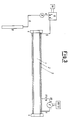
- Figure 5 shows a monitoring device according to the present invention by way of example.
- the cathodic protection current is produced by the generator G, which is a mains-fed potentiostat providing a direct current at its terminals.
- the modulator M feeds the potentiostat with a modulation pulse which causes it to generate the two currents I max and I min at alternate times, so generating a square wave cathodic protection current.
- the voltmeter V is an electrometer, ie a high-impedance voltmeter, which suffers no internal signal drop and thus provides a very accurate measurement.
- the purpose of the change-over switch CT1/CT2 is to enable the modulation current and the corresponding voltage variation to be read, these being measured across R rif and between the pipeline 2 and the reference electrode respectively.
- the measurement made by the electrometer can be recorded either by a recorder on paper or by an oscilloscope.
Landscapes
- Chemical & Material Sciences (AREA)
- Engineering & Computer Science (AREA)
- Materials Engineering (AREA)
- Mechanical Engineering (AREA)
- Metallurgy (AREA)
- Organic Chemistry (AREA)
- Physics & Mathematics (AREA)
- General Physics & Mathematics (AREA)
- Prevention Of Electric Corrosion (AREA)
- Investigating Or Analyzing Materials By The Use Of Electric Means (AREA)
- Measurement Of Resistance Or Impedance (AREA)
Claims (7)
- Verfahren zur Kontrolle der Funktionstüchtigkeit der Schutzschicht (3) von unterirdischen oder versenkten metallischen Strukturen (2), welche kathodisch geschützt sind, wie etwa Fluid-Transportrohre (1), wobei die Kontrolle auf der Messung des elektrischen Widerstandes, welcher durch die Schutzschicht (3) gegeben wird, beruht, dadurch gekennzeichnet, daß der kathodische Schutzstrom (I) mit Rechteckpulsen moduliert ist, so daß ein Modulationsstrom I* an die Struktur angelegt wird, und die Potentialänderung, auf Grund des Ohm'schen Spannungsabfalles ΔV*, welcher in der Struktur durch den angelegten Modulationsstrom I* induziert wird, gemessen wird, der Widerstand, welcher durch die Schutzschicht geliefert wird, aus der Gleichung R = ΔV*/I* bestimmt wird, wobei der Modulationsstrom des kathodischen Schutzes mit ΔV* gemessen wird, und weiters dadurch gekennzeichnet, daß die Überwachung kontinuierlich durch permanentes Modulieren des kathodischen Schutzstromes (I), welcher an der Struktur anliegt, durchgeführt wird, wobei die Intensität des Modulationsstromes I* so ist, daß ein kathodischer Schutz immer aufrechterhalten wird.
- Verfahren zur Kontrolle der Funktionstüchtigkeit der Schutzschicht von metallischen Strukturen nach Anspruch 1, dadurch gekennzeichnet, daß die Modulation des Stromes symmetrisch bei einem niedrigen Modulationsniveau, welches unter 10 % liegt, durchgeführt wird.
- Verfahren zur Kontrolle der Funktionstüchtigkeit der Schutzschicht von metallischen Strukturen nach Anspruch 2, dadurch gekennzeichnet, daß die Strommodulation symmetrisch bei einem niedrigen Modulationsniveau, welches zwischen 0,5 % und 5 % liegt, durchgeführt wird.
- Verfahren zur Kontrolle der Funktionstüchtigkeit der Schutzschicht von metallischen Strukturen nach einem oder mehreren der vorhergehenden Ansprüche, dadurch gekennzeichnet, daß die Modulationsfrequenz unter 100 Hz liegt und das Verhältnis der zwei Halbperioden zwischen 0,001 und 1000 beträgt.
- Verfahren zur Kontrolle der Funktionstüchtigkeit der Schutzschicht von metallischen Strukturen nach Anspruch 4, dadurch gekennzeichnet, daß die Modulationsfrequenz zwischen 0,05 und 1 Hz liegt und das Verhältnis der zwei Halbperioden zwischen 0,1 und 10 beträgt.
- Verfahren zur Kontrolle der Funktionstüchtigkeit der Schutzschicht von metallischen Strukturen nach einem oder mehreren der vorhergehenden Ansprüche, dadurch gekennzeichnet, daß mit der Änderung des Zustandes der Schutzschicht (3) mit der Zeit die Meßgenauigkeit im wesentlichen konstant gehalten wird, indem das Niveau der Modulation des angelegten kathodischen Schutzstromes (I) geändert wird.
- Vorrichtung zur Kontrolle der Funktionstüchtigkeit der Schutzschicht (3) von metallischen Strukturen (2) durch das Verfahren nach einem oder mehreren der vorhergehenden Ansprüche, bestehend aus wenigstens einem Generator (G) zum Anlegen eines kathodischen Schutzstromes an die Strukturen und wenigstens einem Modulator (M) zum Modulieren des Stromes mit Rechteckpulsen und umfassend in seinem elektrischen Stromkreis einen bekannten Widerstand (Rrif), welcher es ermöglicht, daß der Modulationsstrom I* mit Hilfe von einer Spannungsmessung, auf der Basis des Verhältnisses I* = ΔVrif/Rrif, gemessen wird, und worin sowohl I* als auch ΔV*, wobei ΔV* den Ohm'schen Spannungsabfall, welcher in den Strukturen durch I* induziert wird, bedeutet, mit dem selben elektrischen Meßgerät (V) hoher Impedanz gemessen werden, welches durch einen Umschalt-Schalter (CT1/CT2) geschaltet werden kann, um den Spannungsunterschied zwischen den zwei Enden des Widerstandes (Rrif) oder zwischen dem Rohr (2) und der Bezugselektrode (11) zu messen.
Applications Claiming Priority (2)
| Application Number | Priority Date | Filing Date | Title |
|---|---|---|---|
| IT2140789 | 1989-08-01 | ||
| IT8921407A IT1230366B (it) | 1989-08-01 | 1989-08-01 | Procedimento per il controllo in continuo dell'integrita' del rivestimento protettivo di strutture metalliche interrate e dispositivi per la sua realizzazione. |
Publications (2)
| Publication Number | Publication Date |
|---|---|
| EP0411689A1 EP0411689A1 (de) | 1991-02-06 |
| EP0411689B1 true EP0411689B1 (de) | 1994-11-09 |
Family
ID=11181309
Family Applications (1)
| Application Number | Title | Priority Date | Filing Date |
|---|---|---|---|
| EP90201949A Expired - Lifetime EP0411689B1 (de) | 1989-08-01 | 1990-07-18 | Verfahren zur kontinuierlichen Kontrolle der Funktionstüchtigkeit von unterirdischen metallischen Strukturen und Vorrichtungen zu seiner Realisierung |
Country Status (8)
| Country | Link |
|---|---|
| EP (1) | EP0411689B1 (de) |
| JP (1) | JPH0387669A (de) |
| AR (1) | AR246804A1 (de) |
| AT (1) | ATE114056T1 (de) |
| CA (1) | CA2021859A1 (de) |
| DE (1) | DE69014002T2 (de) |
| EG (1) | EG19018A (de) |
| IT (1) | IT1230366B (de) |
Cited By (2)
| Publication number | Priority date | Publication date | Assignee | Title |
|---|---|---|---|---|
| RU2104440C1 (ru) * | 1992-03-11 | 1998-02-10 | СНАМ С.п.А. | Способ контроля текущего состояния и обнаружения отслоения защитного покрытия заглубленных или подповерхностных трубопроводов и других металлических конструкций |
| RU2120133C1 (ru) * | 1990-12-14 | 1998-10-10 | Эниричерке С.П.А. | Способ контроля случайных повреждений защитного покрытия подземных или погруженных металлоконструкций и устройство для его осуществления |
Families Citing this family (19)
| Publication number | Priority date | Publication date | Assignee | Title |
|---|---|---|---|---|
| FR2671192A1 (fr) * | 1990-12-27 | 1992-07-03 | Gaz De France | Procede et appareil pour la verification de l'etat d'isolement electrique d'un ouvrage electriquement conducteur. |
| FR2703458B1 (fr) * | 1993-03-31 | 1995-05-24 | Gaz De France | Procédé et dispositif de mesure du potentiel électrochimique réel d'un élément de construction dans un électrolyte tel une conduite enfouie dans le sol, protégée cathodiquement contre la corrosion. |
| FR2707113B1 (fr) * | 1993-06-30 | 1995-08-18 | Electricite De France | Procédé de vérification de l'état d'un câble enterré du type comprenant un écran métallique et une gaine de protection mécanique et dispositif de mise en Óoeuvre de ce procédé. |
| RU2169385C2 (ru) * | 1998-10-05 | 2001-06-20 | Омский научно-исследовательский институт приборостроения | Система дистанционного контроля состояния изоляции трубопровода |
| DE10105139A1 (de) | 2001-02-06 | 2002-08-22 | Wella Ag | Elektrisch leitfähige Polymere in kosmetischen Mitteln |
| RU2263333C2 (ru) * | 2003-07-24 | 2005-10-27 | Общество с ограниченной ответственностью "Севергазпром" | Способ обнаружения нарушений изоляционного покрытия подземного трубопровода |
| JP4820815B2 (ja) * | 2004-03-16 | 2011-11-24 | オーチス エレベータ カンパニー | エレベータ荷重支持部材の状態を監視する電気信号適用方法 |
| EP1730066B1 (de) * | 2004-03-16 | 2010-10-20 | Otis Elevator Company | Erfassung von verschleiss und versagen eines aufzuglasttragglieds |
| RU2263933C1 (ru) * | 2004-06-15 | 2005-11-10 | Федеральное государственное унитарное предприятие Омский научно-исследовательский институт приборостроения | Система дистанционного контроля состояния изоляции трубопровода |
| JP4632434B2 (ja) * | 2005-05-09 | 2011-02-16 | 高圧ガス保安協会 | 配管診断装置 |
| RU2290656C1 (ru) * | 2005-07-13 | 2006-12-27 | Общество с ограниченной ответственностью Научно-производственное предприятие "Диарес" | Способ контроля наличия замыканий трубопровода, оборудованного катодной защитой, с патроном подземных коммуникаций |
| DE102005036508B4 (de) | 2005-07-29 | 2007-07-12 | Eupec Pipecoatings Gmbh | Verfahren und Vorrichtung zur Überwachung und Detektierung von Beschichtungsdefekten einer erd- oder wasserverlegten Rohrleitung |
| DE102007025917B4 (de) * | 2007-06-02 | 2009-11-12 | Herrenknecht Ag | Verfahren und Vorrichtung zur Überprüfung der Umhüllung einer Rohrleitung während des Einzugs in ein mit Flüssigkeit gefülltes Bohrloch |
| JP5016471B2 (ja) * | 2007-12-19 | 2012-09-05 | 株式会社神鋼環境ソリューション | 溶融炉 |
| DE102012017415A1 (de) | 2012-08-28 | 2014-03-06 | Salzgitter Mannesmann Line Pipe Gmbh | Verfahren und Vorrichtung zur Überwachung der Wirksamkeit des kathodischen Korrosionsschutzes von im Erdreich verlegten Anlagen aus Metall |
| CN109488889B (zh) * | 2018-11-09 | 2023-05-12 | 上海金艺检测技术有限公司 | 在役金属管道绝缘内衬层状况的在线检测方法 |
| CN110596204A (zh) * | 2019-09-18 | 2019-12-20 | 岭澳核电有限公司 | 一种核电站管道内衬胶层破损情况检测方法和系统 |
| RU2746108C1 (ru) * | 2020-05-15 | 2021-04-07 | Общество с ограниченной ответственностью "Завод нефтегазовой аппаратуры Анодъ" | Способ защиты от коррозии подземного трубопровода |
| RU2743885C1 (ru) * | 2020-08-05 | 2021-03-01 | Общество с ограниченной ответственностью «Техохрана» | Способ и устройство обнаружения участков перезащиты металла трубопровода |
Family Cites Families (7)
| Publication number | Priority date | Publication date | Assignee | Title |
|---|---|---|---|---|
| DE2361547A1 (de) * | 1973-12-11 | 1975-06-19 | Karl Heinz Ortmann | Kathodischer korrosionsschutz mit einem vom abschaltpotential gesteuertem fremdstromschutzgeraet |
| DE2545325C3 (de) * | 1975-10-09 | 1979-03-22 | Siemens Ag, 1000 Berlin Und 8000 Muenchen | Schaltungsanordnung zur Messung des Isolationswiderstandes erdfreier Starkstromschaltungen |
| US4280124A (en) * | 1978-10-12 | 1981-07-21 | Wuertele James W | Corrosion detector |
| US4255242A (en) * | 1979-08-09 | 1981-03-10 | Freeman Industries, Inc. | Reference electrode IR drop corrector for cathodic and anodic protection systems |
| GB2132226B (en) * | 1982-12-21 | 1986-08-13 | Nippon Light Metal Co | Cathodic protection of aluminium articles |
| US4658365A (en) * | 1984-02-02 | 1987-04-14 | Electric Power Research Institute, Inc. | Device for in-situ monitoring of corrosion rate of cathodically polarized metals |
| US4823072A (en) * | 1986-09-04 | 1989-04-18 | Walcott Kenneth J | Measurement of the polarized potential of buried pipeline having impressed current cathodic protection |
-
1989
- 1989-08-01 IT IT8921407A patent/IT1230366B/it active
-
1990
- 1990-07-18 EP EP90201949A patent/EP0411689B1/de not_active Expired - Lifetime
- 1990-07-18 DE DE69014002T patent/DE69014002T2/de not_active Expired - Fee Related
- 1990-07-18 AT AT90201949T patent/ATE114056T1/de not_active IP Right Cessation
- 1990-07-24 CA CA002021859A patent/CA2021859A1/en not_active Abandoned
- 1990-07-30 EG EG44690A patent/EG19018A/xx active
- 1990-07-31 AR AR90317505A patent/AR246804A1/es active
- 1990-08-01 JP JP2204964A patent/JPH0387669A/ja active Pending
Cited By (2)
| Publication number | Priority date | Publication date | Assignee | Title |
|---|---|---|---|---|
| RU2120133C1 (ru) * | 1990-12-14 | 1998-10-10 | Эниричерке С.П.А. | Способ контроля случайных повреждений защитного покрытия подземных или погруженных металлоконструкций и устройство для его осуществления |
| RU2104440C1 (ru) * | 1992-03-11 | 1998-02-10 | СНАМ С.п.А. | Способ контроля текущего состояния и обнаружения отслоения защитного покрытия заглубленных или подповерхностных трубопроводов и других металлических конструкций |
Also Published As
| Publication number | Publication date |
|---|---|
| JPH0387669A (ja) | 1991-04-12 |
| IT8921407A0 (it) | 1989-08-01 |
| EP0411689A1 (de) | 1991-02-06 |
| DE69014002D1 (de) | 1994-12-15 |
| CA2021859A1 (en) | 1991-02-02 |
| AR246804A1 (es) | 1994-09-30 |
| DE69014002T2 (de) | 1995-05-11 |
| EG19018A (en) | 1994-04-30 |
| IT1230366B (it) | 1991-10-18 |
| ATE114056T1 (de) | 1994-11-15 |
Similar Documents
| Publication | Publication Date | Title |
|---|---|---|
| US5404104A (en) | Device and method for monitoring and locating defects in, and detachment of, the protective covering of underground or immersed metal structures or pipelines | |
| EP0411689A1 (de) | Verfahren zur kontinuierlichen Kontrolle der Funktionstüchtigkeit von unterirdischen metallischen Strukturen und Vorrichtungen zu seiner Realisierung | |
| US10883918B2 (en) | Multielectrode probes for monitoring fluctuating stray current effects and AC interference on corrosion of buried pipelines and metal structures | |
| CN112430817B (zh) | 埋地金属管道腐蚀参数测试探头分体式装置及测试方法 | |
| US8310251B2 (en) | System for assessing pipeline condition | |
| JP3120348B2 (ja) | 地下又は浸漬金属構造物の保護被覆の偶発的損傷を監視する方法及び装置 | |
| EP1152235A1 (de) | Vorrichtung zur fortlaufend in Zeit und Raum Feststellung des Korrosionszustandes von vergrabenen metallischen Strukturen | |
| US5331286A (en) | Method for continuously monitoring the soundness of the protective covering on underground metal structures, and devices for its implementation | |
| US4351703A (en) | Cathodic protection monitoring | |
| Elsner | Corrosion rate on reinforced concrete structures determined by electrochemical methods | |
| EP0693681A1 (de) | Methode und Gerät zur Messung des ohmischen abfallfreien Potentials und zur Beschichtungsintegrität in Anwesenheit von Streuströmen | |
| US12504453B2 (en) | Method and system for assessing a metallic structure arranged within an electrolyte | |
| US7190154B2 (en) | Method and system for measuring a condition of a structure | |
| Nekoksa | Criteria for design of cathodic protection probes with coupons | |
| Adler Flitton et al. | Simulated Service Testing in Soil | |
| SU998584A1 (ru) | Способ определени степени защищенности подземных магистральных трубопроводов | |
| Robbins | A Novel Approach to Assessing Stray Current Interference Without Potential Interruption | |
| Bianchetti | Survey methods and evaluation techniques | |
| HK40116443A (en) | Assessment of metallic structures in contact with an electrolyte | |
| Kumar et al. | Pipe Corrosion Monitor | |
| Bardalai | Pipeline Rehabilitation Surveys For Prioritizing Coat/Wrap Repairs Of Old Cross-Country Pipelines | |
| West et al. | Civil Engineering Corrosion Control. Volume 2. Cathodic Protection Testing Methods and Instruments | |
| Barlo et al. | Cased Crossing Test Methods | |
| UNDERGROUND | CEOCOR DRESDEN–SECTOR A |
Legal Events
| Date | Code | Title | Description |
|---|---|---|---|
| PUAI | Public reference made under article 153(3) epc to a published international application that has entered the european phase |
Free format text: ORIGINAL CODE: 0009012 |
|
| AK | Designated contracting states |
Kind code of ref document: A1 Designated state(s): AT BE CH DE DK ES FR GB GR IT LI LU NL SE |
|
| 17P | Request for examination filed |
Effective date: 19910406 |
|
| 17Q | First examination report despatched |
Effective date: 19930504 |
|
| GRAA | (expected) grant |
Free format text: ORIGINAL CODE: 0009210 |
|
| AK | Designated contracting states |
Kind code of ref document: B1 Designated state(s): AT BE CH DE DK ES FR GB GR IT LI LU NL SE |
|
| PG25 | Lapsed in a contracting state [announced via postgrant information from national office to epo] |
Ref country code: IT Free format text: LAPSE BECAUSE OF FAILURE TO SUBMIT A TRANSLATION OF THE DESCRIPTION OR TO PAY THE FEE WITHIN THE PRE;WARNING: LAPSES OF ITALIAN PATENTS WITH EFFECTIVE DATE BEFORE 2007 MAY HAVE OCCURRED AT ANY TIME BEFORE 2007. THE CORRECT EFFECTIVE DATE MAY BE DIFFERENT FROM THE ONE RECORDED.SCRIBED TIME-LIMIT Effective date: 19941109 Ref country code: ES Free format text: THE PATENT HAS BEEN ANNULLED BY A DECISION OF A NATIONAL AUTHORITY Effective date: 19941109 Ref country code: GR Free format text: LAPSE BECAUSE OF FAILURE TO SUBMIT A TRANSLATION OF THE DESCRIPTION OR TO PAY THE FEE WITHIN THE PRESCRIBED TIME-LIMIT Effective date: 19941109 Ref country code: DK Effective date: 19941109 |
|
| REF | Corresponds to: |
Ref document number: 114056 Country of ref document: AT Date of ref document: 19941115 Kind code of ref document: T |
|
| ET | Fr: translation filed | ||
| REF | Corresponds to: |
Ref document number: 69014002 Country of ref document: DE Date of ref document: 19941215 |
|
| PG25 | Lapsed in a contracting state [announced via postgrant information from national office to epo] |
Ref country code: SE Effective date: 19950209 |
|
| PG25 | Lapsed in a contracting state [announced via postgrant information from national office to epo] |
Ref country code: AT Effective date: 19950718 Ref country code: GB Effective date: 19950718 |
|
| PG25 | Lapsed in a contracting state [announced via postgrant information from national office to epo] |
Ref country code: LI Effective date: 19950731 Ref country code: LU Free format text: LAPSE BECAUSE OF NON-PAYMENT OF DUE FEES Effective date: 19950731 Ref country code: CH Effective date: 19950731 Ref country code: BE Effective date: 19950731 |
|
| PLBE | No opposition filed within time limit |
Free format text: ORIGINAL CODE: 0009261 |
|
| STAA | Information on the status of an ep patent application or granted ep patent |
Free format text: STATUS: NO OPPOSITION FILED WITHIN TIME LIMIT |
|
| 26N | No opposition filed | ||
| BERE | Be: lapsed |
Owner name: ENIRICERCHE S.P.A. Effective date: 19950731 |
|
| PG25 | Lapsed in a contracting state [announced via postgrant information from national office to epo] |
Ref country code: NL Effective date: 19960201 |
|
| GBPC | Gb: european patent ceased through non-payment of renewal fee |
Effective date: 19950718 |
|
| REG | Reference to a national code |
Ref country code: CH Ref legal event code: PL |
|
| NLV4 | Nl: lapsed or anulled due to non-payment of the annual fee |
Effective date: 19960201 |
|
| PG25 | Lapsed in a contracting state [announced via postgrant information from national office to epo] |
Ref country code: DE Effective date: 19960402 |
|
| PG25 | Lapsed in a contracting state [announced via postgrant information from national office to epo] |
Ref country code: FR Effective date: 19960430 |
|
| REG | Reference to a national code |
Ref country code: FR Ref legal event code: ST |
|
| REG | Reference to a national code |
Ref country code: FR Ref legal event code: ST |
|
| REG | Reference to a national code |
Ref country code: FR Ref legal event code: ST |