EP0411737A2 - Ecrou en cage composé avec doigts d'arrêt et méthode de sa fabrication - Google Patents
Ecrou en cage composé avec doigts d'arrêt et méthode de sa fabrication Download PDFInfo
- Publication number
- EP0411737A2 EP0411737A2 EP90301879A EP90301879A EP0411737A2 EP 0411737 A2 EP0411737 A2 EP 0411737A2 EP 90301879 A EP90301879 A EP 90301879A EP 90301879 A EP90301879 A EP 90301879A EP 0411737 A2 EP0411737 A2 EP 0411737A2
- Authority
- EP
- European Patent Office
- Prior art keywords
- fingers
- spring discs
- slots
- cage
- nut
- Prior art date
- Legal status (The legal status is an assumption and is not a legal conclusion. Google has not performed a legal analysis and makes no representation as to the accuracy of the status listed.)
- Granted
Links
Images
Classifications
-
- B—PERFORMING OPERATIONS; TRANSPORTING
- B21—MECHANICAL METAL-WORKING WITHOUT ESSENTIALLY REMOVING MATERIAL; PUNCHING METAL
- B21D—WORKING OR PROCESSING OF SHEET METAL OR METAL TUBES, RODS OR PROFILES WITHOUT ESSENTIALLY REMOVING MATERIAL; PUNCHING METAL
- B21D53/00—Making other particular articles
- B21D53/24—Making other particular articles nuts or like thread-engaging members
-
- F—MECHANICAL ENGINEERING; LIGHTING; HEATING; WEAPONS; BLASTING
- F16—ENGINEERING ELEMENTS AND UNITS; GENERAL MEASURES FOR PRODUCING AND MAINTAINING EFFECTIVE FUNCTIONING OF MACHINES OR INSTALLATIONS; THERMAL INSULATION IN GENERAL
- F16B—DEVICES FOR FASTENING OR SECURING CONSTRUCTIONAL ELEMENTS OR MACHINE PARTS TOGETHER, e.g. NAILS, BOLTS, CIRCLIPS, CLAMPS, CLIPS OR WEDGES; JOINTS OR JOINTING
- F16B37/00—Nuts or like thread-engaging members
- F16B37/12—Nuts or like thread-engaging members with thread-engaging surfaces formed by inserted coil-springs, discs, or the like; Independent pieces of wound wire used as nuts; Threaded inserts for holes
-
- F—MECHANICAL ENGINEERING; LIGHTING; HEATING; WEAPONS; BLASTING
- F16—ENGINEERING ELEMENTS AND UNITS; GENERAL MEASURES FOR PRODUCING AND MAINTAINING EFFECTIVE FUNCTIONING OF MACHINES OR INSTALLATIONS; THERMAL INSULATION IN GENERAL
- F16B—DEVICES FOR FASTENING OR SECURING CONSTRUCTIONAL ELEMENTS OR MACHINE PARTS TOGETHER, e.g. NAILS, BOLTS, CIRCLIPS, CLAMPS, CLIPS OR WEDGES; JOINTS OR JOINTING
- F16B39/00—Locking of screws, bolts or nuts
- F16B39/22—Locking of screws, bolts or nuts in which the locking takes place during screwing down or tightening
- F16B39/28—Locking of screws, bolts or nuts in which the locking takes place during screwing down or tightening by special members on, or shape of, the nut or bolt
- F16B39/284—Locking by means of elastic deformation
-
- Y—GENERAL TAGGING OF NEW TECHNOLOGICAL DEVELOPMENTS; GENERAL TAGGING OF CROSS-SECTIONAL TECHNOLOGIES SPANNING OVER SEVERAL SECTIONS OF THE IPC; TECHNICAL SUBJECTS COVERED BY FORMER USPC CROSS-REFERENCE ART COLLECTIONS [XRACs] AND DIGESTS
- Y10—TECHNICAL SUBJECTS COVERED BY FORMER USPC
- Y10S—TECHNICAL SUBJECTS COVERED BY FORMER USPC CROSS-REFERENCE ART COLLECTIONS [XRACs] AND DIGESTS
- Y10S411/00—Expanded, threaded, driven, headed, tool-deformed, or locked-threaded fastener
- Y10S411/924—Coupled nut and bolt
- Y10S411/929—Thread lock
- Y10S411/937—Distorted nut
Definitions
- the present invention relates to free spinning laminated nuts utilizing laminations of hex shaped hardened coned-disc springs, having a central opening tapped to match threads on an associated bolt and a method for making such nuts.
- the noted laminated nuts are free running on the bolt until seated.
- a locking force between the nut and bolt results from the application of additional torque and rotation after initial seating.
- the additional torque compresses and partially flattens the conical spring discs or spring washers whereby a mechanical interference occurs between the thread flanks of the nut and bolt; it is believed that this is at least partially due to the change in hole size of the nut as the conical discs flatten.
- the resultant thread interference and retained spring load between thread flanks resists unloading that might otherwise occur as a result of tensile or vibrational loads.
- the independently loaded conical spring threaded segments when flattened create a thread interference that tends to lock the nut against rotation or loosening when subject to such loads.
- Laminated nuts have been constructed of a hexagonal shape facilitating the application and use of wrenching tools similar to conventional, solid nut constructions.
- Such previous designs of laminated lock nuts have used symmetrical cages with six fingers or petals, one operative with each of the flats of the laminated, hexagonal configuration. At the same time each of the cage fingers overengaged the exterior surface of the associated flat. With such a construction the wrenching tool engaged the cage fingers and the application and/or removal torque was applied to the laminated nut through the cage.
- the cage literally covering the exterior surface of the stacked discs or laminations was somewhat difficult and costly to manufacture and also added to the cost of assembling the discs within the cage.
- a cage having fewer than six fingers, with each of the fingers being nested in a slot or groove in the surface of the associated flat of the disc.
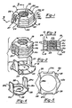
- a laminated nut 10 embodying features of the present invention, is shown and includes a series of hex shaped hardened coned, disc springs 14a-d which are held in an assembled, stacked relationship via a cage 16.
- the laminated nut 10 has a top side 18 and a bottom side 20.
- the nut 10 should be mounted onto the bolt with the bottom side 20 being the leading end of the nut 10 as it is threaded onto the bolt and hence with the top side 18 being the trailing end.
- the laminations or springs 14a-d define a central bore 22 which is threaded to be matably, threadably received upon the bolt.
- the laminations or disc springs 14a-d are initially dished axially outwardly from the bottom side 20 towards the top side 18.
- the cage 16 can be formed of sheet metal and includes a bottom plate portion 23 and a plurality of axially extending fingers 24.
- the cage 16 has a clearance opening 29 in line with and larger than threaded bore 22 to permit easy passage of the associated bolt.
- both the cage 16 and disc springs 14a-d were constructed of an AISI 1050 or AISI 1070 spring steel and hardened to a Rockwell hardness of between around Rc 39 and Rc 45.
- two such fingers 24 are utilized as shown. However, certain advantages of the invention can be realized where two or more such fingers are used.
- two axially extending fingers 24 are circumferentially arranged on diametrically opposite sides of the plate portion 22 with each being in line with two corresponding diametrically opposite flats of the hexagonally shaped outer surface of the laminations or disc springs 14a-d.
- Each of the disc springs 14a-d has its two opposite flats grooved or slotted which, when assembled, define two continuous axially extending slots 25.
- the radial depth of the slots 25 is greater than the thickness of the fingers 24 such that the fingers 24 will be nested or located substantially completely in the slots 25.
- the outer end portions of the fingers 24 are folded radially inwardly to define retaining tabs 26 which grip the uppermost disc spring 14d and thereby hold the components together.
- the plate portion 22 is provided to be of a generally circular contour having a diameter D generally equal to the distance D1 across the peaks of the disc springs 14a-d.
- both the disc springs 14a-d and the cage 16 are in an unhardened condition before assembly, i.e. as in Figure 2.
- the central bore 22 is tapped and the assembled nut 10 is then thermally hardened.
- the fingers overengaged each of the flats of the disc springs and hence enclosed the disc springs. This made the thermal hardening process of the assembled nut more difficult and at times resulted in non-uniform hardening of the disc springs.
- the cage 16 is generally open facilitating the attainment of a more uniform hardness of the disc springs 14a-d from heat treatment of the nut 10.
- FIG. 4-6 Another form of cage and nut assembly is shown in Figures 4-6 where components similar to like components in the embodiment of Figures 1-3 are given the same numerical designation with the addition of the letter postscript "a". For purposes of simplicity all components will not be described and the description of the similarly numbered counterpart in Figures 1-3 can be considered to apply.
- the embodiment of Figures 4-6 shows another cage structure designed to preclude improper orientation of the laminated nut onto the associated bolt.
- the cage 16a has a bottom plate portion 23a which is hexagonally shaped to generally match the shape of the disc springs 14a-d.
- the plate portion 23 is provided with a plurality of radially outwardly extending ears or protrusions 28.
- the protrusions 28 prevent gripping of the nut 10a from the bottom side 20a thereby precluding an operator from installing the laminated nut 10a in a reverse or improper direction on the associated bolt. While four protrusions 28 are provided a plurality of protrusions 28 more or less than four could be effectively used.
- the protrusions 28 and the circular plate portion 23 of enlarged area also provide for obvious visual orientation by the operator and limit driving engagement during installation with hand service tools such as box, open ends or adjustable wrenches.
- the laminated nut 10 of the present invention can be manufactured by a direct and simple process.
- the laminated nut 10 of Figures 1-3 is shown being manufactured; it is understood, however, that the nut 10a with modified cage 16a could be similarly manufactured.
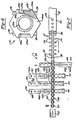
- FIG. 7 a multistation machine 30 is schematically shown.
- a flat strip or stock of material 32 is fed into the machine 30 from one side for forming the cage 16.
- the clearance opening 29 in the bottom plate portion 23 is punched.
- one half of two adjacent sides of cage blanks 16′ are blanked at blanking station 36 to form the fingers 24 which are formed in two successive blanking steps.
- the fingers 24 are folded upwardly from the bottom plate portion 23 to extend axially therefrom to the orientation shown in Figure 2.
- disc springs 14a-d are formed and assembled one at a time into the partially formed cage 16′ which is open as shown in Figure 2.
- a flat strip or stock of material 48 is fed transversely to the direction of feed of the strip 32.
- the opening for the central bore 22 is first punched at punch station 40a.
- the slots 25 are punched at a second, square punch station 40b.
- the first disc spring 14a is blanked out from the strip 48 and assembled into the open cage 16′.
- stations 42-46 The same procedure is followed at stations 42-46.
- a flat strip or stock of material 50 is fed transversely to the direction of feed of the strip 32.
- the opening for the central bore 22 is first punched at punch station 42a.
- the slots 25 are punched at a second, square punch station 42b.
- the second disc spring 14b is blanked out from the strip 50 and assembled into the open cage 16′.
- a flat strip or stock of material 52 is fed transversely to the direction of feed of the strip 32.
- the opening for the central bore 22 is first punched at punch station 44a.
- the slots 25 are punched at a second, square punch station 44b.
- the third disc spring 14c is blanked out from the strip 52 and assembled into the open cage 16′.
- a flat strip or stock of material 54 is fed transversely to the direction of feed of the strip 32.
- the opening for the central bore 22 is first punched at punch station 46a.
- the slots 25 are punched at a second, square punch station 46b.
- the fourth disc spring 14d is blanked out from the strip 54 and assembled into the open cage 16′.
- the assembled nut is moved to a folding station 56 where the upper ends of the fingers 24 are folded radially inwardly to form the retaining tabs 26.
- the corners 27 of the disc springs 14a-d can be skived or deformed inwardly to form the corners 27′ partially closing the slots 25 to retain the fingers 24 within the slots 25 as previously described.
- the bridge of material 59 connecting adjacent ones of the cages 16 is severed at station 58 to separate each nut 10 from the strip of material 32.
- the nut 10 is tapped at a station 60 to define the threaded central bore 22.
- the tapping station 60 can be a part of the multistate machine 30 or be at a separate machine.
- the assembled nut 10 is heat treated to the desired hardness at the heat treat station 62 completing the manufacture of nut 10.
Landscapes
- Engineering & Computer Science (AREA)
- General Engineering & Computer Science (AREA)
- Mechanical Engineering (AREA)
- Springs (AREA)
- Bolts, Nuts, And Washers (AREA)
Applications Claiming Priority (2)
| Application Number | Priority Date | Filing Date | Title |
|---|---|---|---|
| US388658 | 1989-08-02 | ||
| US07/388,658 US4940377A (en) | 1989-08-02 | 1989-08-02 | Laminated nut having cage with nested fingers and method of manufacture |
Publications (3)
| Publication Number | Publication Date |
|---|---|
| EP0411737A2 true EP0411737A2 (fr) | 1991-02-06 |
| EP0411737A3 EP0411737A3 (en) | 1991-08-14 |
| EP0411737B1 EP0411737B1 (fr) | 1993-10-27 |
Family
ID=23534982
Family Applications (1)
| Application Number | Title | Priority Date | Filing Date |
|---|---|---|---|
| EP90301879A Expired - Lifetime EP0411737B1 (fr) | 1989-08-02 | 1990-02-21 | Ecrou en cage composé avec doigts d'arrêt et méthode de sa fabrication |
Country Status (5)
| Country | Link |
|---|---|
| US (2) | US4940377A (fr) |
| EP (1) | EP0411737B1 (fr) |
| JP (1) | JP2854917B2 (fr) |
| CA (1) | CA2010847C (fr) |
| DE (1) | DE69004184T2 (fr) |
Cited By (3)
| Publication number | Priority date | Publication date | Assignee | Title |
|---|---|---|---|---|
| EP0790417A1 (fr) * | 1996-02-13 | 1997-08-20 | Urama S.r.l. | Ecrou autobloquant |
| GB2447297A (en) * | 2007-03-08 | 2008-09-10 | Rolls Royce Plc | Retaining nested articles using bent tabs |
| CN110043535A (zh) * | 2019-04-22 | 2019-07-23 | 浙江农业商贸职业学院 | 一种汽车用补偿螺母 |
Families Citing this family (26)
| Publication number | Priority date | Publication date | Assignee | Title |
|---|---|---|---|---|
| US5049017A (en) * | 1990-05-21 | 1991-09-17 | Pac Fasteners | Laminated nut with anti-spin off structure and method of making nut |
| NZ272517A (en) * | 1994-07-08 | 1998-05-27 | Werner Co | Ladder support bracket, second portion conforms with and extends along the rail to which it is attached |
| US5507517A (en) * | 1994-08-22 | 1996-04-16 | Chrysler Corporation | Nut and washer assemblage for bushing |
| US5938038A (en) * | 1996-08-02 | 1999-08-17 | Dial Tool Industries, Inc. | Parts carrier strip and apparatus for assembling parts in such a strip |
| DE10107231A1 (de) * | 2001-02-16 | 2002-08-22 | Emhart Inc | Befestigung für einen elektrischen Kontakt |
| US7021875B2 (en) * | 2001-10-30 | 2006-04-04 | Newfrey Llc | Coated, weldable fastener, a method of preventing adherence of a second coating to a fastener portion, and a method fastening |
| AU2003301586A1 (en) * | 2002-10-23 | 2004-05-13 | Fabristeel Products, Inc. | Self-attaching female fasteners and method of forming female fastener elements |
| US20040136805A1 (en) * | 2002-10-28 | 2004-07-15 | Rex Miller | Fastener for spanning a large gap |
| US7090454B2 (en) * | 2003-07-24 | 2006-08-15 | Floyd Bell, Inc. | Ratchet interlocking housing |
| US7192231B2 (en) * | 2004-04-05 | 2007-03-20 | Newfrey Llc | Cage nut with non-cross threading angled cage |
| US7857566B2 (en) * | 2005-07-14 | 2010-12-28 | Reactive Spring Fasteners, Llc | Reactive fasteners |
| US7462007B2 (en) * | 2004-07-14 | 2008-12-09 | Paul Sullivan | Reactive biasing fasteners |
| US7484420B2 (en) * | 2005-10-18 | 2009-02-03 | Mjsi, Inc. | Fastener assembly and method |
| DE102005050513B4 (de) * | 2005-10-21 | 2008-04-17 | A. Raymond Et Cie | Vorrichtung zum Verbinden mit einer Schraube |
| US20080193259A1 (en) * | 2007-02-12 | 2008-08-14 | Hill Ross S | Laminated wheel lug nut |
| US7789608B2 (en) * | 2007-02-13 | 2010-09-07 | Illinois Tool Works Inc. | Laminated nut with tension indicator |
| US8047753B2 (en) * | 2008-07-22 | 2011-11-01 | The Boeing Company | Insulating washers |
| US7878747B2 (en) * | 2008-07-22 | 2011-02-01 | The Boeing Company | Insulating cover for fasteners used in high temperature environments |
| KR101172868B1 (ko) * | 2010-05-24 | 2012-08-09 | 이용국 | 록크 너트 및 이를 구비하는 체결 유닛 |
| CN103175461B (zh) * | 2013-02-28 | 2015-07-08 | 航天精工股份有限公司 | 螺母收口槽深度尺寸的检测装置 |
| US9551456B2 (en) | 2015-02-03 | 2017-01-24 | United Technologies Corporation | Belleville washer nut plate |
| WO2018003226A1 (fr) * | 2016-06-30 | 2018-01-04 | Smc株式会社 | Écrou |
| US10767386B2 (en) * | 2016-07-15 | 2020-09-08 | Safety Maker, Inc. | Washer assembly for use in affixing a guardrail support to a surface |
| CN107246434B (zh) * | 2017-06-07 | 2019-07-16 | 江西电力职业技术学院 | 防滑螺帽以及防滑螺帽扳手套件 |
| JP7043264B2 (ja) * | 2018-01-11 | 2022-03-29 | 株式会社アルテック | 壁面取付ユニット |
| US20240229990A9 (en) * | 2022-10-25 | 2024-07-11 | Petróleo Brasileiro S.A. - Petrobras | Nut guide |
Family Cites Families (11)
| Publication number | Priority date | Publication date | Assignee | Title |
|---|---|---|---|---|
| US1874829A (en) * | 1930-09-17 | 1932-08-30 | Swanstrom Carl Arthur | Method of making self-locking nuts |
| US1990718A (en) * | 1931-04-23 | 1935-02-12 | Elastic Stop Nut Corp | Process of making nuts |
| US2090125A (en) * | 1937-05-25 | 1937-08-17 | Akron Selle Company | Nut |
| US2320032A (en) * | 1941-10-20 | 1943-05-25 | Charles C Akin | Lock nut |
| US2659406A (en) * | 1947-06-10 | 1953-11-17 | Locke Louis Peer | Apparatus for forming and assembling electrical terminals |
| US2784428A (en) * | 1955-02-09 | 1957-03-12 | Russell E Curran | Method of making a lock nut assembly from a plurality of sheet metal laminations |
| US3233262A (en) * | 1963-02-18 | 1966-02-08 | Vollman Walter | Method of producing locknuts by assembling laminae in a housing |
| US3461935A (en) * | 1967-02-01 | 1969-08-19 | Giulio Monticelli | Resilient self-blocking nut |
| IT1115369B (it) * | 1977-07-14 | 1986-02-03 | Norma Spa | Dispositivo a dado autobloccante e procedimento per la sua fabbricazione |
| US4383787A (en) * | 1980-09-16 | 1983-05-17 | Reynolds Richard L | Free spinning laminated nut with automatic lock |
| CA1297709C (fr) * | 1986-12-08 | 1992-03-24 | Pac-Fasteners | Ecrou du type lamelle pouvant etre pose d'un seul cote |
-
1989
- 1989-08-02 US US07/388,658 patent/US4940377A/en not_active Expired - Lifetime
-
1990
- 1990-02-21 DE DE90301879T patent/DE69004184T2/de not_active Expired - Lifetime
- 1990-02-21 EP EP90301879A patent/EP0411737B1/fr not_active Expired - Lifetime
- 1990-02-23 CA CA002010847A patent/CA2010847C/fr not_active Expired - Lifetime
- 1990-03-09 JP JP2059816A patent/JP2854917B2/ja not_active Expired - Lifetime
- 1990-03-16 US US07/494,472 patent/US4984319A/en not_active Expired - Fee Related
Cited By (3)
| Publication number | Priority date | Publication date | Assignee | Title |
|---|---|---|---|---|
| EP0790417A1 (fr) * | 1996-02-13 | 1997-08-20 | Urama S.r.l. | Ecrou autobloquant |
| GB2447297A (en) * | 2007-03-08 | 2008-09-10 | Rolls Royce Plc | Retaining nested articles using bent tabs |
| CN110043535A (zh) * | 2019-04-22 | 2019-07-23 | 浙江农业商贸职业学院 | 一种汽车用补偿螺母 |
Also Published As
| Publication number | Publication date |
|---|---|
| JPH0369807A (ja) | 1991-03-26 |
| DE69004184D1 (de) | 1993-12-02 |
| CA2010847A1 (fr) | 1991-02-02 |
| US4940377A (en) | 1990-07-10 |
| EP0411737A3 (en) | 1991-08-14 |
| JP2854917B2 (ja) | 1999-02-10 |
| DE69004184T2 (de) | 1994-04-28 |
| EP0411737B1 (fr) | 1993-10-27 |
| CA2010847C (fr) | 1997-03-25 |
| US4984319A (en) | 1991-01-15 |
Similar Documents
| Publication | Publication Date | Title |
|---|---|---|
| US4940377A (en) | Laminated nut having cage with nested fingers and method of manufacture | |
| US6109849A (en) | Tee nut | |
| EP0371579B1 (fr) | Assemblage d'écrou et boulon | |
| US5049017A (en) | Laminated nut with anti-spin off structure and method of making nut | |
| US3276499A (en) | Flush-driven self-piercing and clinching nut and method of securing to a member | |
| US2549393A (en) | Fastening | |
| US3181584A (en) | Screw-and-washer pre-assembly | |
| US5445483A (en) | Female clinch fastener with cold-formed locking flange and associated installation method | |
| US5238344A (en) | Tee nut | |
| CA2049138C (fr) | Ecrou a bord dentele et procede de fabrication correspondant | |
| EP0041593A1 (fr) | Elément de fixation et procédé pour son montage | |
| US2846701A (en) | Method of forming a sheet metal lock nut | |
| GB2067700A (en) | Threaded fastener and structural joint attained therewith | |
| US5503596A (en) | Method of manufacturing tee nuts | |
| US3314326A (en) | Self-threading nut with interrupted threads | |
| JPH11241714A (ja) | 素材、板状構成要素への素材取付け方法、構成要素アッセンブリーおよびダイスボタン | |
| EP0903508A1 (fr) | Ecrou de blocage non déformé ayant une gorge | |
| US5827027A (en) | Nut free from inadvertent loosening and a method of making same | |
| US5017079A (en) | Laminated nut with one way installation | |
| EP1081396A2 (fr) | Ecrou de blocage | |
| US3687501A (en) | Non-rotatable fastener | |
| US3978758A (en) | Bolt and process of forming same | |
| EP0255528B1 (fr) | Assemblage de fixation de goujons | |
| US5452974A (en) | Deformable locking fastener system and method of use | |
| DE19680507B3 (de) | Anordnung zum Verbinden eines Außenrings und einer Welle einer homokinetischen Verbindung |
Legal Events
| Date | Code | Title | Description |
|---|---|---|---|
| PUAI | Public reference made under article 153(3) epc to a published international application that has entered the european phase |
Free format text: ORIGINAL CODE: 0009012 |
|
| AK | Designated contracting states |
Kind code of ref document: A2 Designated state(s): DE FR GB IT SE |
|
| PUAL | Search report despatched |
Free format text: ORIGINAL CODE: 0009013 |
|
| AK | Designated contracting states |
Kind code of ref document: A3 Designated state(s): DE FR GB IT SE |
|
| 17P | Request for examination filed |
Effective date: 19910725 |
|
| 17Q | First examination report despatched |
Effective date: 19920414 |
|
| GRAA | (expected) grant |
Free format text: ORIGINAL CODE: 0009210 |
|
| AK | Designated contracting states |
Kind code of ref document: B1 Designated state(s): DE FR GB IT SE |
|
| REF | Corresponds to: |
Ref document number: 69004184 Country of ref document: DE Date of ref document: 19931202 |
|
| ET | Fr: translation filed | ||
| ITF | It: translation for a ep patent filed | ||
| PLBE | No opposition filed within time limit |
Free format text: ORIGINAL CODE: 0009261 |
|
| STAA | Information on the status of an ep patent application or granted ep patent |
Free format text: STATUS: NO OPPOSITION FILED WITHIN TIME LIMIT |
|
| 26N | No opposition filed | ||
| EAL | Se: european patent in force in sweden |
Ref document number: 90301879.4 |
|
| PGFP | Annual fee paid to national office [announced via postgrant information from national office to epo] |
Ref country code: FR Payment date: 20010131 Year of fee payment: 12 |
|
| PGFP | Annual fee paid to national office [announced via postgrant information from national office to epo] |
Ref country code: SE Payment date: 20010201 Year of fee payment: 12 |
|
| REG | Reference to a national code |
Ref country code: GB Ref legal event code: IF02 |
|
| PG25 | Lapsed in a contracting state [announced via postgrant information from national office to epo] |
Ref country code: SE Free format text: LAPSE BECAUSE OF NON-PAYMENT OF DUE FEES Effective date: 20020222 |
|
| EUG | Se: european patent has lapsed |
Ref document number: 90301879.4 |
|
| PG25 | Lapsed in a contracting state [announced via postgrant information from national office to epo] |
Ref country code: FR Free format text: LAPSE BECAUSE OF NON-PAYMENT OF DUE FEES Effective date: 20021031 |
|
| REG | Reference to a national code |
Ref country code: FR Ref legal event code: ST |
|
| PG25 | Lapsed in a contracting state [announced via postgrant information from national office to epo] |
Ref country code: IT Free format text: LAPSE BECAUSE OF NON-PAYMENT OF DUE FEES Effective date: 20050221 |
|
| PGFP | Annual fee paid to national office [announced via postgrant information from national office to epo] |
Ref country code: GB Payment date: 20090227 Year of fee payment: 20 |
|
| PGFP | Annual fee paid to national office [announced via postgrant information from national office to epo] |
Ref country code: DE Payment date: 20090331 Year of fee payment: 20 |
|
| REG | Reference to a national code |
Ref country code: GB Ref legal event code: PE20 Expiry date: 20100220 |
|
| PG25 | Lapsed in a contracting state [announced via postgrant information from national office to epo] |
Ref country code: GB Free format text: LAPSE BECAUSE OF EXPIRATION OF PROTECTION Effective date: 20100220 |
|
| PG25 | Lapsed in a contracting state [announced via postgrant information from national office to epo] |
Ref country code: DE Free format text: LAPSE BECAUSE OF EXPIRATION OF PROTECTION Effective date: 20100221 |