EP0411942A2 - Système de laser paramÀ©triquement pulsé - Google Patents
Système de laser paramÀ©triquement pulsé Download PDFInfo
- Publication number
- EP0411942A2 EP0411942A2 EP90308525A EP90308525A EP0411942A2 EP 0411942 A2 EP0411942 A2 EP 0411942A2 EP 90308525 A EP90308525 A EP 90308525A EP 90308525 A EP90308525 A EP 90308525A EP 0411942 A2 EP0411942 A2 EP 0411942A2
- Authority
- EP
- European Patent Office
- Prior art keywords
- parametric
- pulsed
- light beams
- pulsed laser
- laser according
- Prior art date
- Legal status (The legal status is an assumption and is not a legal conclusion. Google has not performed a legal analysis and makes no representation as to the accuracy of the status listed.)
- Granted
Links
- 230000003287 optical effect Effects 0.000 claims abstract description 36
- 239000013307 optical fiber Substances 0.000 claims abstract description 24
- 239000006185 dispersion Substances 0.000 claims abstract description 21
- 239000013078 crystal Substances 0.000 claims abstract description 19
- XSQUKJJJFZCRTK-UHFFFAOYSA-N Urea Chemical compound NC(N)=O XSQUKJJJFZCRTK-UHFFFAOYSA-N 0.000 claims abstract description 6
- 239000004202 carbamide Substances 0.000 claims abstract description 6
- 239000000835 fiber Substances 0.000 claims description 7
- 230000001419 dependent effect Effects 0.000 claims 1
- 239000011295 pitch Substances 0.000 description 6
- 230000005540 biological transmission Effects 0.000 description 2
- 238000010586 diagram Methods 0.000 description 2
- 230000010355 oscillation Effects 0.000 description 2
- 230000001427 coherent effect Effects 0.000 description 1
- 238000010276 construction Methods 0.000 description 1
- 230000003247 decreasing effect Effects 0.000 description 1
- 230000000694 effects Effects 0.000 description 1
- 238000000034 method Methods 0.000 description 1
Images



Classifications
-
- H—ELECTRICITY
- H01—ELECTRIC ELEMENTS
- H01S—DEVICES USING THE PROCESS OF LIGHT AMPLIFICATION BY STIMULATED EMISSION OF RADIATION [LASER] TO AMPLIFY OR GENERATE LIGHT; DEVICES USING STIMULATED EMISSION OF ELECTROMAGNETIC RADIATION IN WAVE RANGES OTHER THAN OPTICAL
- H01S3/00—Lasers, i.e. devices using stimulated emission of electromagnetic radiation in the infrared, visible or ultraviolet wave range
- H01S3/005—Optical devices external to the laser cavity, specially adapted for lasers, e.g. for homogenisation of the beam or for manipulating laser pulses, e.g. pulse shaping
- H01S3/0057—Temporal shaping, e.g. pulse compression, frequency chirping
-
- G—PHYSICS
- G02—OPTICS
- G02F—OPTICAL DEVICES OR ARRANGEMENTS FOR THE CONTROL OF LIGHT BY MODIFICATION OF THE OPTICAL PROPERTIES OF THE MEDIA OF THE ELEMENTS INVOLVED THEREIN; NON-LINEAR OPTICS; FREQUENCY-CHANGING OF LIGHT; OPTICAL LOGIC ELEMENTS; OPTICAL ANALOGUE/DIGITAL CONVERTERS
- G02F1/00—Devices or arrangements for the control of the intensity, colour, phase, polarisation or direction of light arriving from an independent light source, e.g. switching, gating or modulating; Non-linear optics
- G02F1/35—Non-linear optics
- G02F1/39—Non-linear optics for parametric generation or amplification of light, infrared or ultraviolet waves
-
- G—PHYSICS
- G02—OPTICS
- G02B—OPTICAL ELEMENTS, SYSTEMS OR APPARATUS
- G02B6/00—Light guides; Structural details of arrangements comprising light guides and other optical elements, e.g. couplings
- G02B6/24—Coupling light guides
- G02B6/26—Optical coupling means
- G02B6/28—Optical coupling means having data bus means, i.e. plural waveguides interconnected and providing an inherently bidirectional system by mixing and splitting signals
- G02B6/293—Optical coupling means having data bus means, i.e. plural waveguides interconnected and providing an inherently bidirectional system by mixing and splitting signals with wavelength selective means
- G02B6/29304—Optical coupling means having data bus means, i.e. plural waveguides interconnected and providing an inherently bidirectional system by mixing and splitting signals with wavelength selective means operating by diffraction, e.g. grating
- G02B6/29305—Optical coupling means having data bus means, i.e. plural waveguides interconnected and providing an inherently bidirectional system by mixing and splitting signals with wavelength selective means operating by diffraction, e.g. grating as bulk element, i.e. free space arrangement external to a light guide
- G02B6/2931—Diffractive element operating in reflection
-
- G—PHYSICS
- G02—OPTICS
- G02B—OPTICAL ELEMENTS, SYSTEMS OR APPARATUS
- G02B6/00—Light guides; Structural details of arrangements comprising light guides and other optical elements, e.g. couplings
- G02B6/24—Coupling light guides
- G02B6/26—Optical coupling means
- G02B6/28—Optical coupling means having data bus means, i.e. plural waveguides interconnected and providing an inherently bidirectional system by mixing and splitting signals
- G02B6/293—Optical coupling means having data bus means, i.e. plural waveguides interconnected and providing an inherently bidirectional system by mixing and splitting signals with wavelength selective means
- G02B6/29379—Optical coupling means having data bus means, i.e. plural waveguides interconnected and providing an inherently bidirectional system by mixing and splitting signals with wavelength selective means characterised by the function or use of the complete device
- G02B6/29392—Controlling dispersion
- G02B6/29394—Compensating wavelength dispersion
Definitions
- This invention relates to a parametric pulse laser.
- the width of light pulses emitted from lasers has to be reduced as much as possible.
- One of the techniques commonly employed to oscillate pulse lasers is to input pulse light to a parametric element so that parametric pulse light is obtained.
- a parametric pulsed laser comprises a pulsed laser source for emitting a pulsed laser beam; light input means for receiving the pulsed laser beam and inputting exciting pulsed light beams into a parametric oscillator simultaneously from a plurality of directions; the parametric oscillator including a parametric element, for producing parametric pulsed light beams having different wavelengths; correcting optical means for converting the parametric pulsed light beams into coaxial pulsed light beams; and group dispersion compensating means for compensating for group dispersion of the coaxial pulsed light beams.
- the present invention provides a parametric pulsed laser that is capable of producing shorter output light pulses without causing dispersion.
- wavelength of the output visible light having a frequency ⁇ 1 shifts to the longer range and wavelength of the output infrared light having a frequency ⁇ 2 shifts to the shorter range, as the angle formed between the input ultraviolet light and the optic axis of the urea crystal is reduced from 90 degrees.
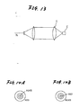
- a visible light output having the wavelength ⁇ 1 may be produced as shown in Fig. 14A or 14B.
- Fig. 14A shows, the output light from a parametric element made of a urea crystal has an inner blue region and an outer red region, with the wavelength increasing from the center outward.
- Fig. 14B shows, the output light from a parametric element made of a ⁇ -BaB2O4 crystal has an inner red region and an outer blue region, with the wavelength decreasing from the center outward.
- the multi-wavelength pulse light beams emitted from the parametric oscillator are corrected into coaxial beams by a correcting optical means, and the coaxial pulse light beams from this correcting optical means is compensated by a group dispersion compensating means to produce pulse light beams consisting of shorter pulses. For instance, if the frequency range of light beams having the frequencies ⁇ 1 and ⁇ 2 are written as ⁇ 1 and ⁇ 2, respectively, the resulting light pulses have pulse widths on the order of 1/ ⁇ 1 and 1/ ⁇ 2, respectively.
- a first embodiment of the present invention is shown in Fig. 1 and provides a parametric pulse laser which comprises: an exciting mode-locked laser 10 that outputs exciting laser light; a light input means 11 composed of lenses and other elements for inputting the beams of exciting pulse laser light to a parametric oscillator 12 in multiple directions; the parametric oscillator 12 for generating wavelength-converted multi-wavelength pulse laser light; a dichroic mirror 14 for rejecting a component of frequency ⁇ 2 from the pulse light emitted from the parametric oscillator 12; a correcting optical means 16 for correcting the component of wavelength ⁇ 1 passing through the dichroic mirror 14 so as to produce coaxial pulse light; and a group dispersion compensating means 18 that compensates for the group dispersion of the light pulses output from the correcting optical means 16.
- An example of the light input means is the lens system shown in Fig. 13, which is already described above.
- the parametric oscillator 12 is composed of a parametric element 20 positioned between a resonator mirror 12A and an output mirror 12B.
- the resonator length of the parametric oscillator 12 is designed to be an integral multiple or a reciprocal of an integer of the resonator length of the exciting mode-locked laser 10.
- the correcting optical means 16 is composed of a non-dispersive lens 16A, an optical fiber 16B and another non-dispersive lens 16C.
- the non-dispersive lenses 16A and 16C are formed of a non-dispersive medium, so even if they are shaped like ordinary convex lenses, they are capable of focusing the beams of multi-wavelength light on one point or collimating multi-wavelength light diverging from a single point. Since it is difficult in practical applications to fabricate an optical medium that is non-dispersive over a broad range of wavelengths, it is recommended to use achromatic lenses each consisting of the combination of several dispersive media.
- the non-dispersive lenses 16A and 16C may be formed of an ordinary optical medium to have an aspheric surface so that the lens is capable of focusing on one point the light in a blue to red wavelength range which depends on a crystal constituting the parametric element 20, or capable of collimating such light from one point.
- Fig. 3 shows a second embodiment of the present invention, in which the non-dispersive lens 16A in the correcting optical means 16 is replaced by a Fresnel lens 16D.
- the Fresnel lens 16D should be so designed that the pitch between annular segments varies in the radial direction to insure that the visible light in a blue to red range which depends on a crystal constituting the parametric element 20 is focused on one point.
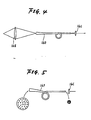
- the correcting optical means 16 may employ a usual dispersive lens 16Z and a tapered optical fiber 16E as in the third embodiment shown in Fig. 4.
- the tapered optical fiber 16E may be replaced by a bundle of single-mode fibers to form a tapered optical fiber 16F as in the fourth embodiment shown in Fig. 5.
- the dispersive effect of the optical fiber in the correcting optical means 16 causes a component of the longer wavelength to come earlier than a component of the shorter wavelength.
- two diffraction gratings 18A and 18B are arranged parallel to each other as shown in Fig. 6.
- the operating principle employed in this arrangement is that light having the shorter wavelength travels over a shorter optical path than light having the longer wavelength, as shown in Fig. 7.
- the light pulses of different wavelengths can be well timed. In this way, the wideband light generated from the parametric oscillator 12, whose frequency range may have spread to ⁇ 1, can be converted to light of short pulses on the order of 1/ ⁇ 1.
- gratings 18A - 18D may be used as shown in Fig. 8.
- the embodiment shown in Fig. 8 has the advantages that an incident beam will not spread but instead is produced as an output beam having the same diameter, and that the distance between opposed gratings is halved.
- a pair of triangular prisms or four triangular prisms that operate on the same principle as described above may be used as the group dispersion compensating means 18.
- an optical fiber having a reverse dispersion to the fiber used in the correcting optical means 16 may be used.
- the two fibers can be directly coupled to obviate the need for the non-dispersive lens 16C.
- the mode-locked laser 10 is used as a light source for exciting the parametric element 20. It should, however, be noted that this is not the sole example of the exciting light source that can be used in the present invention and another source such as a Q-switched laser may be used. If a Q-switched laser is used, there is no need to insure that the resonator length of the parametric oscillator 12 is either an integral multiple or a reciprocal of an integer of the resonator length of the exciting laser.
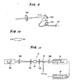
- the light input means 11 includes a cylindrical lens (in the example of Fig. 13, only the lens L is made cylindrical), and the correcting optical means 16 includes a cylindrical lens 16C and a reflection grating 16G.
- the crystal optic axis of the parametric element 20 is selected in such a way that the output light ⁇ 1 from the parametric element 20, which has been focused by the cylindrical lens of the light input means 11 and wavelength-converted by the parametric element 20, will have a wavelength profile as shown in Fig. 10. If the grating pitch of the grating 16G is optimized, the visible light reflected from that grating will converge at one point irrespective of its color, as shown in Fig. 9. The same is true with the case where a transmission grating is used in place of the reflection grating.
- the pulse light is focused by the reflection grating 16G or a transmission grating on one end of either the optical fiber or the tapered fiber which are already described above.
- the fifth embodiment of Fig. 9 only includes the single optical fiber 16B, it is preferable, to more effectively utilize the parametric output light, to employ linearly arranged optical fibers.
- the non-dispersive lens 16C is also made cylindrical.
- the grating described above may be replaced by a triangular prism. If desired, such a grating and triangular prism may be adapted to also work as part of the group dispersion compensating means 18.
- FIG. 11 A sixth embodiment of the present invention is shown in Fig. 11.
- a ⁇ -BaB2O4 crystal having a phase-matching angle ( ⁇ ) of 23.1 degrees is used as the parametric element 20 and an Ar ion laser 10A is used as an exciting pulse light source.
- the parametric element 20 is excited by pulse laser light generated from the Ar ion laser 10A at a wavelength of 514.5 nm.
- Shown by numerals 20A and 20B are lenses.
- the ⁇ -BaB2O4 crystal has the characteristic shown in Fig. 12, so by merely allowing the output beam from the Ar ion laser 10A to be weakly focused, wideband coherent light containing two components of frequencies ⁇ 1 and ⁇ 2 in the wavelength range of 800 - 1440 nm can be obtained at a time at a phase-matching angle of 23.1 ⁇ 0.3 degrees, and this offers the advantage that there is no need to separate the two light components ⁇ 1 and ⁇ 2. It should be noted here that similar results can be attained even if the mode-locked laser 10 is used in place of the Ar ion laser 10A.
- the component of frequency ⁇ 1 of the pulse light from the parametric oscillator 12 is converted to short pulses, but desired short pulses can also be obtained from the light component of frequency ⁇ 2 by arranging the correcting optical means and the group dispersion compensating means for the component of ⁇ 2 in the same manner as described above.
- the pitch in the Fresnel lens 16D should be varied from ordinary Fresnel lenses; if the parametric element 20 is composed of a urea crystal, the pitch should increase from the center outward, and if the element 20 is made of a ⁇ -BaB2O4 crystal, the pitch should decrease from the center outward.
- a Fresnel lens having a reverse profile of pitches need to be used for the light component having the frequency ⁇ 2 to obtain short pulses. In this case, too, the duration of pulses can be reduced down to about 1/ ⁇ 2. Accordingly, ultrashort light pulses can be obtained whether the frequency of light is ⁇ 1 or ⁇ 2.
- an optical fiber is used in the correcting optical means 16 but, if desired, this may be replaced by a fiber amplifier which amplifies the parametric pulse light before it is input to the group dispersion compensating means 18.
- the parametric pulse laser of the present invention offers the outstanding advantage that wavelength-converted laser light pulses shorter than the original light pulses can be produced with high efficiency.
Landscapes
- Physics & Mathematics (AREA)
- Nonlinear Science (AREA)
- Electromagnetism (AREA)
- Optics & Photonics (AREA)
- Engineering & Computer Science (AREA)
- Plasma & Fusion (AREA)
- General Physics & Mathematics (AREA)
- Lasers (AREA)
Applications Claiming Priority (4)
| Application Number | Priority Date | Filing Date | Title |
|---|---|---|---|
| JP202220/89 | 1989-08-03 | ||
| JP20222089 | 1989-08-03 | ||
| JP247282/89 | 1989-09-22 | ||
| JP1247282A JP2505892B2 (ja) | 1989-08-03 | 1989-09-22 | パラメトリツクパルスレ―ザ |
Publications (3)
| Publication Number | Publication Date |
|---|---|
| EP0411942A2 true EP0411942A2 (fr) | 1991-02-06 |
| EP0411942A3 EP0411942A3 (en) | 1992-01-15 |
| EP0411942B1 EP0411942B1 (fr) | 1994-10-12 |
Family
ID=26513245
Family Applications (1)
| Application Number | Title | Priority Date | Filing Date |
|---|---|---|---|
| EP90308525A Expired - Lifetime EP0411942B1 (fr) | 1989-08-03 | 1990-08-02 | Système de laser paramétriquement pulsé |
Country Status (4)
| Country | Link |
|---|---|
| US (1) | US5119385A (fr) |
| EP (1) | EP0411942B1 (fr) |
| JP (1) | JP2505892B2 (fr) |
| DE (1) | DE69013265T2 (fr) |
Cited By (1)
| Publication number | Priority date | Publication date | Assignee | Title |
|---|---|---|---|---|
| FR2699695A1 (fr) * | 1992-12-22 | 1994-06-24 | Thomson Csf | Source cohérente optique à émission accordable. |
Families Citing this family (16)
| Publication number | Priority date | Publication date | Assignee | Title |
|---|---|---|---|---|
| JP3309430B2 (ja) * | 1992-07-28 | 2002-07-29 | ソニー株式会社 | レーザ光発生装置 |
| US5648866A (en) * | 1995-06-12 | 1997-07-15 | Sandia Corporation | Optimized achromatic phase-matching system and method |
| US5740190A (en) * | 1996-05-23 | 1998-04-14 | Schwartz Electro-Optics, Inc. | Three-color coherent light system |
| DE19744302B4 (de) * | 1996-06-04 | 2008-04-17 | Carl Zeiss Jena Gmbh | Vorrichtung zur Einkopplung der Strahlung von Kurzpulslasern in einem mikroskopischen Strahlengang |
| DE19622359B4 (de) * | 1996-06-04 | 2007-11-22 | Carl Zeiss Jena Gmbh | Vorrichtung zur Einkopplung der Strahlung von Kurzpulslasern in einem mikroskopischen Strahlengang |
| US6771417B1 (en) * | 1997-08-01 | 2004-08-03 | Carl Zeiss Jena Gmbh | Applications of adaptive optics in microscopy |
| DE19827139C2 (de) * | 1998-06-18 | 2002-01-31 | Zeiss Carl Jena Gmbh | Mikroskop mit einem über eine Lichtleitfaser eingekoppelten Kurzpulslaser |
| JP4008609B2 (ja) * | 1999-01-26 | 2007-11-14 | 三菱電機株式会社 | レーザ装置およびレーザ加工装置 |
| US6650682B1 (en) | 1999-04-30 | 2003-11-18 | University Of New Mexico | Bi-directional short pulse ring laser |
| DE10331906B4 (de) * | 2003-07-15 | 2005-06-16 | Leica Microsystems Heidelberg Gmbh | Lichtquelle mit einem Mikrostruktuierten optischen Element und Mikroskop mit Lichtquelle |
| US8339580B2 (en) * | 2004-06-30 | 2012-12-25 | Lawrence Livermore National Security, Llc | Sensor-guided threat countermeasure system |
| EP2526592B1 (fr) * | 2010-01-22 | 2021-06-23 | Newport Corporation | Oscillateur paramétrique optique largement accordable |
| FR2963707B1 (fr) * | 2010-08-03 | 2013-07-12 | Ecole Polytech | Dispositif d'amplification a derive de frequence pour un laser impulsionel |
| FR2965673B1 (fr) * | 2010-09-30 | 2013-08-23 | Ecole Polytech | Dispositif d'amplification a derive de frequence pour un laser impulsionnel |
| JP2014096445A (ja) * | 2012-11-08 | 2014-05-22 | Japan Atomic Energy Agency | レーザー装置及びレーザー光増幅方法 |
| WO2015130651A1 (fr) | 2014-02-28 | 2015-09-03 | Imra America, Inc. | Génération et distribution d'impulsions ultracourtes à longueurs d'ondes multiples, avec des applications en microscopie |
Family Cites Families (8)
| Publication number | Priority date | Publication date | Assignee | Title |
|---|---|---|---|---|
| US3720884A (en) * | 1970-03-23 | 1973-03-13 | Massachusetts Inst Technology | Method and apparatus for compression of optical laser pulses |
| US4200846A (en) * | 1977-09-29 | 1980-04-29 | The United States Of America As Represented By The United States Department Of Energy | Efficient laser amplifier using sequential pulses of different wavelengths |
| US4250465A (en) * | 1978-08-29 | 1981-02-10 | Grumman Aerospace Corporation | Radiation beam deflection system |
| US4349907A (en) * | 1980-04-23 | 1982-09-14 | The United Stated Of America As Represented By The Department Of Energy | Broadly tunable picosecond IR source |
| US4639923A (en) * | 1984-05-21 | 1987-01-27 | Cornell Research Foundation, Inc. | Optical parametric oscillator using urea crystal |
| US4764930A (en) * | 1988-01-27 | 1988-08-16 | Intelligent Surgical Lasers | Multiwavelength laser source |
| US4914663A (en) * | 1988-04-22 | 1990-04-03 | The Board Of Trustees Of Leland Stanford, Jr. University | Generation of short high peak power pulses from an injection mode-locked Q-switched laser oscillator |
| JPH0233416A (ja) * | 1988-07-22 | 1990-02-02 | Yamaha Motor Co Ltd | V型多気筒エンジン |
-
1989
- 1989-09-22 JP JP1247282A patent/JP2505892B2/ja not_active Expired - Fee Related
-
1990
- 1990-08-01 US US07/561,981 patent/US5119385A/en not_active Expired - Lifetime
- 1990-08-02 EP EP90308525A patent/EP0411942B1/fr not_active Expired - Lifetime
- 1990-08-02 DE DE69013265T patent/DE69013265T2/de not_active Expired - Fee Related
Cited By (2)
| Publication number | Priority date | Publication date | Assignee | Title |
|---|---|---|---|---|
| FR2699695A1 (fr) * | 1992-12-22 | 1994-06-24 | Thomson Csf | Source cohérente optique à émission accordable. |
| EP0604303A1 (fr) * | 1992-12-22 | 1994-06-29 | Thomson-Csf | Source cohérente optique à émission accordable |
Also Published As
| Publication number | Publication date |
|---|---|
| DE69013265D1 (de) | 1994-11-17 |
| JP2505892B2 (ja) | 1996-06-12 |
| US5119385A (en) | 1992-06-02 |
| DE69013265T2 (de) | 1995-05-24 |
| EP0411942B1 (fr) | 1994-10-12 |
| EP0411942A3 (en) | 1992-01-15 |
| JPH03155690A (ja) | 1991-07-03 |
Similar Documents
| Publication | Publication Date | Title |
|---|---|---|
| EP0411942B1 (fr) | Système de laser paramétriquement pulsé | |
| US4685107A (en) | Dispersion compensated fiber Raman oscillator | |
| USRE35215E (en) | Frequency converted laser diode and lens system therefor | |
| US6519269B1 (en) | Wavelength tuneable laser source | |
| US4063106A (en) | Optical fiber Raman oscillator | |
| JP2020523793A (ja) | 超高密度波長ビーム結合レーザシステム | |
| JP2007527616A (ja) | レーザー発光特性調整のためのボリューム・ブラッグ・グレーティングの使用 | |
| JPH10186246A (ja) | レーザビームの補正方法及び装置 | |
| EP0833190A3 (fr) | Dispositif de raccordement d'une première tube à diamètre faible à une autre et son usage dans la chromatographie en phase gazeuse | |
| US6967976B2 (en) | Laser with reflective etalon tuning element | |
| US6765940B2 (en) | Anamorphic prism wavelength locker | |
| US5052013A (en) | Pulsed laser | |
| US4710937A (en) | Laser system | |
| EP0608866B1 (fr) | Appareil générateur laser | |
| US4868515A (en) | Narrow-bandwidth unstable laser resonator | |
| US20060153255A1 (en) | Terahertz wave generation system | |
| JPS6390188A (ja) | レーザ送信器 | |
| US6327278B1 (en) | Diode laser pumped multimode waveguide laser, particularly fiber laser | |
| US6959023B1 (en) | Laser with reflective etalon tuning element | |
| JPS59165488A (ja) | フアイバラマンレ−ザ | |
| US6535542B1 (en) | Multi-wavelength laser light source | |
| JPH04121718A (ja) | 光高調波発生装置 | |
| JP4421159B2 (ja) | 制限されたスペクトル間隔を仕切る矩形の応答型光学フィルタ | |
| JPH0318833A (ja) | 高調波発生素子および高調波発生装置 | |
| JPS6132488A (ja) | 半導体レ−ザ装置 |
Legal Events
| Date | Code | Title | Description |
|---|---|---|---|
| PUAI | Public reference made under article 153(3) epc to a published international application that has entered the european phase |
Free format text: ORIGINAL CODE: 0009012 |
|
| AK | Designated contracting states |
Kind code of ref document: A2 Designated state(s): DE FR GB |
|
| PUAL | Search report despatched |
Free format text: ORIGINAL CODE: 0009013 |
|
| AK | Designated contracting states |
Kind code of ref document: A3 Designated state(s): DE FR GB |
|
| 17P | Request for examination filed |
Effective date: 19920626 |
|
| 17Q | First examination report despatched |
Effective date: 19931214 |
|
| GRAA | (expected) grant |
Free format text: ORIGINAL CODE: 0009210 |
|
| AK | Designated contracting states |
Kind code of ref document: B1 Designated state(s): DE FR GB |
|
| REF | Corresponds to: |
Ref document number: 69013265 Country of ref document: DE Date of ref document: 19941117 |
|
| ET | Fr: translation filed | ||
| PLBE | No opposition filed within time limit |
Free format text: ORIGINAL CODE: 0009261 |
|
| STAA | Information on the status of an ep patent application or granted ep patent |
Free format text: STATUS: NO OPPOSITION FILED WITHIN TIME LIMIT |
|
| 26N | No opposition filed | ||
| REG | Reference to a national code |
Ref country code: GB Ref legal event code: IF02 |
|
| PGFP | Annual fee paid to national office [announced via postgrant information from national office to epo] |
Ref country code: GB Payment date: 20030730 Year of fee payment: 14 |
|
| PGFP | Annual fee paid to national office [announced via postgrant information from national office to epo] |
Ref country code: DE Payment date: 20030814 Year of fee payment: 14 |
|
| PG25 | Lapsed in a contracting state [announced via postgrant information from national office to epo] |
Ref country code: GB Free format text: LAPSE BECAUSE OF NON-PAYMENT OF DUE FEES Effective date: 20040802 |
|
| PG25 | Lapsed in a contracting state [announced via postgrant information from national office to epo] |
Ref country code: DE Free format text: LAPSE BECAUSE OF NON-PAYMENT OF DUE FEES Effective date: 20050301 |
|
| GBPC | Gb: european patent ceased through non-payment of renewal fee |
Effective date: 20040802 |
|
| PGFP | Annual fee paid to national office [announced via postgrant information from national office to epo] |
Ref country code: FR Payment date: 20080818 Year of fee payment: 19 |
|
| REG | Reference to a national code |
Ref country code: FR Ref legal event code: ST Effective date: 20100430 |
|
| PG25 | Lapsed in a contracting state [announced via postgrant information from national office to epo] |
Ref country code: FR Free format text: LAPSE BECAUSE OF NON-PAYMENT OF DUE FEES Effective date: 20090831 |