EP0412004A2 - Rotierender Zerkleinerer und Behälter zur Manipulation von Objekten, welche giftige oder radioaktive Elemente enthalten - Google Patents
Rotierender Zerkleinerer und Behälter zur Manipulation von Objekten, welche giftige oder radioaktive Elemente enthalten Download PDFInfo
- Publication number
- EP0412004A2 EP0412004A2 EP90402194A EP90402194A EP0412004A2 EP 0412004 A2 EP0412004 A2 EP 0412004A2 EP 90402194 A EP90402194 A EP 90402194A EP 90402194 A EP90402194 A EP 90402194A EP 0412004 A2 EP0412004 A2 EP 0412004A2
- Authority
- EP
- European Patent Office
- Prior art keywords
- knives
- rotor
- objects
- knife
- counter
- Prior art date
- Legal status (The legal status is an assumption and is not a legal conclusion. Google has not performed a legal analysis and makes no representation as to the accuracy of the status listed.)
- Ceased
Links
- 231100000331 toxic Toxicity 0.000 title claims description 8
- 230000002588 toxic effect Effects 0.000 title claims description 8
- 230000002285 radioactive effect Effects 0.000 title claims description 7
- 230000002441 reversible effect Effects 0.000 claims abstract description 5
- 239000002699 waste material Substances 0.000 claims description 24
- 239000003638 chemical reducing agent Substances 0.000 claims description 3
- 230000005484 gravity Effects 0.000 claims description 2
- 230000001131 transforming effect Effects 0.000 claims 1
- 231100000701 toxic element Toxicity 0.000 abstract 1
- 239000000463 material Substances 0.000 description 7
- 230000000903 blocking effect Effects 0.000 description 3
- 239000011521 glass Substances 0.000 description 3
- 125000006850 spacer group Chemical group 0.000 description 3
- 238000009825 accumulation Methods 0.000 description 2
- 230000000694 effects Effects 0.000 description 2
- 239000007788 liquid Substances 0.000 description 2
- 238000009206 nuclear medicine Methods 0.000 description 2
- 229910000497 Amalgam Inorganic materials 0.000 description 1
- 229910000760 Hardened steel Inorganic materials 0.000 description 1
- RYXPMWYHEBGTRV-UHFFFAOYSA-N Omeprazole sodium Chemical compound [Na+].N=1C2=CC(OC)=CC=C2[N-]C=1S(=O)CC1=NC=C(C)C(OC)=C1C RYXPMWYHEBGTRV-UHFFFAOYSA-N 0.000 description 1
- 230000001627 detrimental effect Effects 0.000 description 1
- 238000007599 discharging Methods 0.000 description 1
- 230000002349 favourable effect Effects 0.000 description 1
- 239000011344 liquid material Substances 0.000 description 1
- 238000004519 manufacturing process Methods 0.000 description 1
- 239000000203 mixture Substances 0.000 description 1
- 238000004806 packaging method and process Methods 0.000 description 1
- 239000002901 radioactive waste Substances 0.000 description 1
- 238000010008 shearing Methods 0.000 description 1
- 239000011343 solid material Substances 0.000 description 1
- 239000002910 solid waste Substances 0.000 description 1
Images



Classifications
-
- B—PERFORMING OPERATIONS; TRANSPORTING
- B02—CRUSHING, PULVERISING, OR DISINTEGRATING; PREPARATORY TREATMENT OF GRAIN FOR MILLING
- B02C—CRUSHING, PULVERISING, OR DISINTEGRATING IN GENERAL; MILLING GRAIN
- B02C18/00—Disintegrating by knives or other cutting or tearing members which chop material into fragments
- B02C18/06—Disintegrating by knives or other cutting or tearing members which chop material into fragments with rotating knives
- B02C18/16—Details
- B02C18/24—Drives
-
- B—PERFORMING OPERATIONS; TRANSPORTING
- B02—CRUSHING, PULVERISING, OR DISINTEGRATING; PREPARATORY TREATMENT OF GRAIN FOR MILLING
- B02C—CRUSHING, PULVERISING, OR DISINTEGRATING IN GENERAL; MILLING GRAIN
- B02C18/00—Disintegrating by knives or other cutting or tearing members which chop material into fragments
- B02C18/06—Disintegrating by knives or other cutting or tearing members which chop material into fragments with rotating knives
- B02C18/16—Details
- B02C18/18—Knives; Mountings thereof
- B02C18/182—Disc-shaped knives
-
- B—PERFORMING OPERATIONS; TRANSPORTING
- B02—CRUSHING, PULVERISING, OR DISINTEGRATING; PREPARATORY TREATMENT OF GRAIN FOR MILLING
- B02C—CRUSHING, PULVERISING, OR DISINTEGRATING IN GENERAL; MILLING GRAIN
- B02C18/00—Disintegrating by knives or other cutting or tearing members which chop material into fragments
- B02C18/06—Disintegrating by knives or other cutting or tearing members which chop material into fragments with rotating knives
- B02C18/16—Details
- B02C18/22—Feed or discharge means
- B02C18/2225—Feed means
- B02C18/2291—Feed chute arrangements
-
- B—PERFORMING OPERATIONS; TRANSPORTING
- B02—CRUSHING, PULVERISING, OR DISINTEGRATING; PREPARATORY TREATMENT OF GRAIN FOR MILLING
- B02C—CRUSHING, PULVERISING, OR DISINTEGRATING IN GENERAL; MILLING GRAIN
- B02C19/00—Other disintegrating devices or methods
- B02C19/0056—Other disintegrating devices or methods specially adapted for specific materials not otherwise provided for
- B02C19/0075—Other disintegrating devices or methods specially adapted for specific materials not otherwise provided for specially adapted for disintegrating medical waste
Definitions
- the invention relates to the manipulation of objects, such as small tubes containing toxic or radioactive elements or products, as is the case in research or the nuclear industry, as in nuclear medicine or medical laboratories.
- the invention relates more precisely to the shredders making it possible to considerably reduce the volume of these objects, which must be stored.
- Such a crusher is therefore often associated with enclosures of the glove box type.
- the object of the invention is to remedy these drawbacks by proposing a grinder capable of minimizing the number of blockages, and of being self-unlocking.
- the first main object of the invention is a rotary mill comprising a casing inside which is placed a grid carrying counter knives, a rotor mounted rotating in the casing around an axis of rotation and comprising several knives, a motor for rotating the rotor.
- the rotor consists of discs each carrying knives of a determined thickness and being spaced by a determined distance, the counter knives being inserted between the knives during the rotations of the rotor, the counter knives being spaced apart by a distance greater than the thickness of the knives, but being of a thickness less than the distance separating the knives, so that the rotor can rotate in the grid, without the knives touching the counter knives.
- the fact that the knives and the counter knives are separated promotes grinding and prohibits most blockages. It also promotes the rotation in the opposite direction of the rotor, in order to obtain an unlocking of the mill.
- the rotor discs have the same number of knives and are fixed to each other coaxially with respect to the axis of the rotor offset angularly, so that several knives are not angularly positioned in the same way .
- the discs are fixed so that the knives form oblique rows relative to the axis of rotation of the rotor.
- the motor is reversible and the shape of each knife, in the plane of the disc, is symmetrical with respect to a plane passing through the axis of rotation, so as to cause in both directions of rotation the same phenomenon of grinding of the rotor, the counter knives being divided into two separate groups, the attack phases of the counter knives being the same in the two groups.
- Blockage is also avoided thanks to the fact that the attack phase of the counter knives is placed in the horizontal plane containing the axis of rotation of the rotor, and that the shape of each knife in the plane of its disc is pyramidal, of so that the passage of the leading face of each knife in the plane of the leading face of each counter knife is done gradually, starting at the point located near the base of the knife and ending at its end.
- these have a slightly thinner thickness as one moves away from the center of the disc, the thickness at the end of the blade being approximately equal to 3 mm.
- a worm gear reducer is used so that the rotor rotates at a rotational speed of the order of a few revolutions per minute.
- the crusher has an upper opening in the housing, above the grid, for introducing the objects to be ground and a lower opening in the housing, below the grid, for discharging the crushed waste.
- the crusher is advantageously completed by a loading system placed above the upper opening and comprising: - a bottomless drawer defining an internal volume whose manual access is limited by a ledge; and - a drawer housing inside which the drawer slides, completely surrounding this drawer and having a loading hole placed below the drawer when the latter is in the closed position to prevent the operator's hand from accessing the rotor and only allow objects to be loaded into the crusher when the drawer is in the closed position.
- Means for driving objects placed at the end of each knife, can facilitate or accelerate the grinding.
- a second main object of the invention is an enclosure for handling products or objects containing toxic or radioactive elements, the enclosure being of the glove box type, the handling of the objects being done by an operator placed outside. of the enclosure and by means of gloves and circles of gloves, and having a hole for evacuating objects by gravity in a receptacle.
- a grinder as summarized in the preceding paragraphs, is fixed opposite the discharge hole to grind the products handled in the enclosure and transform them into waste in the form of pieces of small dimensions, to reduce the volume required for the storage of these objects.
- FIG. 1 makes it possible to distinguish the main parts of the mill according to the invention.
- the rotor 10 is mounted rotating around an axis 8 and is driven in rotation by means of an electric motor 4, preferably by means of a speed reducer 6.
- the one shown in FIG. 1 is of the worm and worm type, this being only one example of production. In general, the speed of rotation of the rotor 10 is a few revolutions per minute.
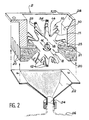
- FIG. 2 specifies the various technical characteristics inherent in the mill according to the invention.
- FIG. 2 Also shown in FIG. 2 is a rotation shaft 16 on which the rotor 10 made up of several discs 14 is fixedly fixed in rotation. This rotational attachment can be effected by means of a key 18.
- a hopper 22 intended to collect the crushed waste. It is commonly fixed on the casing 2.
- the top of its pyramid ends in a neck 24 placed at the bottom of the assembly.
- a storage or transport receptacle 26 such as a container.
- the objects to be shredded are introduced through the upper part of the casing 2, preferably on an inclined plane 28 placed inside the casing 2 to bring the objects against the knives 12, considering the direction of rotation in accordance with that of the hands of a watch.
- the objects are then subjected to a grinding effect, since they are trapped between the knives 12, the counter knives 20 and the lateral internal wall 30 of the casing 2.
- the waste thus obtained is collected in the hopper 22 and accumulated in receptacle 26.
- Figure 3 details the mounting and positioning of the discs 14 on the shaft 16 of the rotor 10.
- each disc 14 has the same number N of knives 12.
- each disc 14 is positioned angularly offset with respect to the other discs 14. For example, considering the disc 14A in the upper part of the figure, it has been positioned so that one of these knives 12A is vertical. The other knives of this disc 14A are therefore positioned as a function thereof.
- the third disc 14C has its upper knife 12C again angularly offset relative to the upper knife 12B of the disc 14B (angle 2W). This offset is then equal to twice the offset between the knives 12A and 12B.
- the offset of the discs 14 relative to one another must be chosen so that two knives of two different discs are never in the same angular position.
- the front end 13A of the knife 12A is the only knife end to pass opposite the vertical line, marked 15 in FIG. 3. Therefore, in Returning to FIG.
- the positioning along the axis 8 of the rotor 10 is done by means of axial spacers 32.
- each knife 12 has a radially elongated trapezoidal shape.
- the shape of each knife must be such that all the points of the attack face 11 of a knife do not correspond at the same time with all of them. the points of the attack face 21 of a counter knife 20.
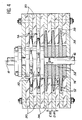
- FIG. 4 specifies even better the respective shapes and positions of the knives 12 and counter knives 20.
- the discs 14 are separated by their axial spacers 32. They each penetrate between two counter knives 20.
- the mounting of the latter in the housing 2 is also done by means of spacers 34 placed between each of the counter knives 20.
- the fixing of the counter knives 20 is symbolized by tightening, by means of a screw-nut system.
- the principle governing the shape and mounting of the knives 12 and the counter knives 20 is that there is a space between the side walls 38 of the knives 12 of the discs 14 and the side wall 39 of the counter knives 20, so as to avoid a phenomenon of contact shearing, similar to that implemented by a pair of scissors.
- the distance D20, separating two counter knives 20 is greater than the thickness E14 separating two discs 14 and the thickness E20 of the counter knives 20 is less than the distance D14 separating two discs 14.
- the rotor 10 in particular, is made of hardened steel.
- the crushing phenomenon can be promoted by the use of drive means, such as small hooks or brushes 36 placed at the end 25 of each knife 12 (see FIG. 2). Indeed, if the objects tend to slip away from the rotational effect of the rotor and remain tangent at the end of the knives 12, hooks or brushes 36 favor the entrainment of these objects.
- the mill according to the invention is equipped with a reversible motor. Indeed, in the event that a blocking or "jamming" phenomenon occurs in the crusher, a rotor 10 rotation control in the opposite direction of usual operation makes it possible to release the knives 12 wedged in the counter knives 20.
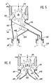
- FIG. 5 shows a first accessory which can be used with the crusher according to the invention, for grinding objects containing both solid materials and liquid materials. It is a sorting device placed in place of the hopper 22 of FIG. 2 to receive the crushed waste.
- This sorting device comprises a main grid 42 inclined inside the sorting hopper 44.
- the crushed waste 46 falls on this grid 42, through which the liquid 48 can easily flow. This is collected in a first container 50 connected to a first neck 52 of the sorting hopper 44.
- the solid waste is removed at the bottom of the grid 42 in a second container 54 connected to the sorting device 40 by a second neck 56 .
- This sorting device can be particularly effective when the crushed objects are small containers, such as vials or syringes containing liquid.
- a second sorting device can be used with the crusher, when the latter is used to grind different materials.
- This second device consists mainly of two receiving channels 41 and 43, placed below the mill, each on one side, vertical to the end of the knives 12, when they come out against the knives 20.
- a spout divider 45 joins the central walls 47 and 49 of the two channels and goes up between the knives 12, in the same way as the counter-knives 20, vertical to the axis of rotation 8.
- the crusher according to the invention is advantageously used on an enclosure for handling objects containing toxic or radioactive elements. Indeed, in nuclear medicine and in medical laboratories, we have to handle many vials or syringes that have contained or still contain radioactive products.
- the standards of ANDRA National Agency for the Management of Radioactive Waste
- the manipulation enclosure of FIG. 7 is of the glove box type. That is to say that the upper part 52 of the enclosure is sealed.
- the manipulation of the objects inside it is done by operators acting inside by means of gloves which are themselves tightly connected to the wall of the enclosure by glove holes 54. They control their handling through a window 56 placed on the upper part 52 of the enclosure.
- the operator can grasp objects 64 in inlet holes 62, placed above a supply device 60. Once an object 64 has been grasped, the hole 62 is filled in with a sliding plug and the The object is placed in a loading device of the crusher.
- this loading system mainly comprises a bottomless drawer 78, partially covered with a flange 80. It is surrounded by a housing 82 inside which it slides.
- the operator opens the drawer 78, loads the object or objects 64 to be ground there and closes the drawer 78 in its housing 82.
- the drawer 78 being bottomless, the objects fall into the crusher 70 thanks to the presence of a hole 83 practiced in the upper part of the mill, and offset from the place where the operator introduces the objects 64.
- access to the rotor of the mill by the operator's hand is defended by a labyrinth consisting of the drawer 78 fitted with its rim 80 and the hole 83 of the grinder.
- a control device can then be constituted by a switch 84 placed at the bottom of the drawer 82 housing, actuated when the drawer 78 comes into its closed position against this switch 84.
- the latter can start on the one hand the rotation of the rotor of the mill 70 and on the other hand, a time delay 86 defining a determined time of rotation of the rotor, so as not to operate the mill 70 excessively.
Landscapes
- Engineering & Computer Science (AREA)
- Food Science & Technology (AREA)
- Environmental & Geological Engineering (AREA)
- Crushing And Pulverization Processes (AREA)
Applications Claiming Priority (2)
| Application Number | Priority Date | Filing Date | Title |
|---|---|---|---|
| FR8910460 | 1989-08-01 | ||
| FR8910460 | 1989-08-01 |
Publications (2)
| Publication Number | Publication Date |
|---|---|
| EP0412004A2 true EP0412004A2 (de) | 1991-02-06 |
| EP0412004A3 EP0412004A3 (en) | 1991-10-23 |
Family
ID=9384433
Family Applications (1)
| Application Number | Title | Priority Date | Filing Date |
|---|---|---|---|
| EP19900402194 Ceased EP0412004A3 (en) | 1989-08-01 | 1990-07-31 | Rotary comminutor and container for manipulating objects containing toxic or radioactive elements |
Country Status (1)
| Country | Link |
|---|---|
| EP (1) | EP0412004A3 (de) |
Cited By (6)
| Publication number | Priority date | Publication date | Assignee | Title |
|---|---|---|---|---|
| WO1997010057A1 (en) * | 1995-09-12 | 1997-03-20 | Niro Separation A/S | A comminution machine |
| DE10158845A1 (de) * | 2001-11-27 | 2003-06-05 | Schleicher & Co Int Ag | Zerkleinerungsvorrichtung für Kleingeräte und Verfahren zur Entsorgung von kontaminierten Kleingeräten |
| RU2471120C2 (ru) * | 2011-01-11 | 2012-12-27 | Федеральное государственное бюджетное образовательное учреждение высшего профессионального образования "Сибирский государственный технологический университет" (СибГТУ) | Устройство для измельчения отходов производства |
| RU2471119C1 (ru) * | 2011-06-17 | 2012-12-27 | Федеральное государственное бюджетное образовательное учреждение высшего профессионального образования "Сибирский государственный технологический университет" (СибГТУ) | Устройство для измельчения отходов производства |
| US20160288132A1 (en) * | 2015-03-31 | 2016-10-06 | Bay Plastics Machinery Company LLC | Vacuum-assisted pelletizer |
| US12023667B1 (en) * | 2020-06-01 | 2024-07-02 | United States Of America As Represented By The Administrator Of Nasa | Extractor for chemical analysis of lipid biomarkers |
Family Cites Families (4)
| Publication number | Priority date | Publication date | Assignee | Title |
|---|---|---|---|---|
| DE2840138A1 (de) * | 1978-09-15 | 1980-03-27 | Josef L Gillessen | Verfahren und vorrichtung zum reinigen (dekontaminieren) von mit strahlenden stoffen verunreinigten kleinteilen |
| US4394983A (en) * | 1981-03-02 | 1983-07-26 | Kaca Corporation | Tire and refuse shredder |
| DE3437719A1 (de) * | 1984-10-15 | 1986-04-17 | Roediger Wilhelm Gmbh Co | Verfahren und vorrichtung zum lagerfaehigmachen von radioaktiv kontaminiertem material |
| US4809915A (en) * | 1988-03-07 | 1989-03-07 | Affald International Inc. | Waste disposal apparatus |
-
1990
- 1990-07-31 EP EP19900402194 patent/EP0412004A3/fr not_active Ceased
Cited By (9)
| Publication number | Priority date | Publication date | Assignee | Title |
|---|---|---|---|---|
| WO1997010057A1 (en) * | 1995-09-12 | 1997-03-20 | Niro Separation A/S | A comminution machine |
| US5992777A (en) * | 1995-09-12 | 1999-11-30 | Niro Separation A/S | Communication machine |
| DE10158845A1 (de) * | 2001-11-27 | 2003-06-05 | Schleicher & Co Int Ag | Zerkleinerungsvorrichtung für Kleingeräte und Verfahren zur Entsorgung von kontaminierten Kleingeräten |
| RU2471120C2 (ru) * | 2011-01-11 | 2012-12-27 | Федеральное государственное бюджетное образовательное учреждение высшего профессионального образования "Сибирский государственный технологический университет" (СибГТУ) | Устройство для измельчения отходов производства |
| RU2471119C1 (ru) * | 2011-06-17 | 2012-12-27 | Федеральное государственное бюджетное образовательное учреждение высшего профессионального образования "Сибирский государственный технологический университет" (СибГТУ) | Устройство для измельчения отходов производства |
| US20160288132A1 (en) * | 2015-03-31 | 2016-10-06 | Bay Plastics Machinery Company LLC | Vacuum-assisted pelletizer |
| US10589283B2 (en) * | 2015-03-31 | 2020-03-17 | Bay Plastics Machinery Company LLC | Vacuum-assisted pelletizer |
| US10875030B2 (en) | 2015-03-31 | 2020-12-29 | Bay Plastics Machinery Company LLC | Vacuum-assisted pelletizer |
| US12023667B1 (en) * | 2020-06-01 | 2024-07-02 | United States Of America As Represented By The Administrator Of Nasa | Extractor for chemical analysis of lipid biomarkers |
Also Published As
| Publication number | Publication date |
|---|---|
| EP0412004A3 (en) | 1991-10-23 |
Similar Documents
| Publication | Publication Date | Title |
|---|---|---|
| CA3075441C (fr) | Deconditionneur a nettoyage ameliore | |
| CA2119495A1 (en) | Fruit and vegetable juice extractor | |
| EP3079994B1 (de) | Vorrichtung und verfahren zum öffnen von behältern mit heterogenen stoffen | |
| EP3628405B1 (de) | Sammel- und zerkleinerungsbehälter für restaurantabfälle | |
| EP2609029A1 (de) | Vorrichtung zur handhabung von trommeln, gerät zur übertragung von pulverstoffen und übertragungsverfahren | |
| EP0600808A1 (de) | Vorrichtung zum Sortieren, Zerkleinern und Konditionieren von Abfall | |
| EP0412004A2 (de) | Rotierender Zerkleinerer und Behälter zur Manipulation von Objekten, welche giftige oder radioaktive Elemente enthalten | |
| KR102274800B1 (ko) | 포장분말의 분진방지용 탈철장치 | |
| FR2943630A1 (fr) | Dispositif d'extraction de liquide contenu dans des recipients en materiau non cassant | |
| FR2558387A1 (fr) | Procede de melange de matieres pouvant s'ecouler comme des matieres en vrac, en un rapport de melange reglable, en tant que partie d'un procede de traitement de ces matieres, et agencement pour la mise en oeuvre de ce procede | |
| EP3670170A1 (de) | Walzwerk für abfälle | |
| FR3015960A1 (fr) | Compacteur a dechets | |
| FR2785205A1 (fr) | Dispositif de broyage de dechets | |
| EP0220100B1 (de) | Zerlegbarer Zerkleinerer für kleine gläserne oder starre plastische Gegenstände | |
| EP3967133A1 (de) | Gehäuse für die vorrichtung eines mähbalkens für astschnitte und mähbalken mit einem solchen gehäuse | |
| EP0007818A1 (de) | Vorrichtung zur Konditionierung toxischer Abfälle | |
| EP1055459B1 (de) | Gezwungene Speisevorrichtung für Kunststoffteilen oder Abfall aller Grössen in Zerkleinerungsvorrichtungen aller Art | |
| EP0534630A1 (de) | Vorrichtung zur Zerkleinerung von Gegenständen | |
| FR2711574A1 (fr) | Dispositif de compactage de récipients plastiques et installation de collecte de récipients. | |
| EP0641602B1 (de) | Press- und Schneidvorrichtung für voluminöse, stark elastische Gegenstände, insbesondere Reifen | |
| FR2711552A1 (fr) | Déchiqueteur de récipients plastiques et installation de collecte de récipients. | |
| WO2006042963A1 (fr) | Dispositif de compactage et vidage de cannettes pour boisson | |
| US4614006A (en) | Apparatus for processing crustaceans | |
| EP0749783B1 (de) | Maschine zum Zerkleinern von Kunststoffteilen | |
| FR2692815A1 (fr) | Dispositif d'emmagasinage et de traitement de déchets urbains, avec tri par courant de Foucault. |
Legal Events
| Date | Code | Title | Description |
|---|---|---|---|
| PUAI | Public reference made under article 153(3) epc to a published international application that has entered the european phase |
Free format text: ORIGINAL CODE: 0009012 |
|
| AK | Designated contracting states |
Kind code of ref document: A2 Designated state(s): DE ES FR IT |
|
| PUAL | Search report despatched |
Free format text: ORIGINAL CODE: 0009013 |
|
| AK | Designated contracting states |
Kind code of ref document: A3 Designated state(s): DE ES FR IT |
|
| 17P | Request for examination filed |
Effective date: 19920326 |
|
| 17Q | First examination report despatched |
Effective date: 19930624 |
|
| STAA | Information on the status of an ep patent application or granted ep patent |
Free format text: STATUS: THE APPLICATION HAS BEEN REFUSED |
|
| 18R | Application refused |
Effective date: 19940708 |