EP0412008A1 - Moteur multicylindre à injection d'essence, comportant quatre soupapes par cylindre - Google Patents
Moteur multicylindre à injection d'essence, comportant quatre soupapes par cylindre Download PDFInfo
- Publication number
- EP0412008A1 EP0412008A1 EP90402202A EP90402202A EP0412008A1 EP 0412008 A1 EP0412008 A1 EP 0412008A1 EP 90402202 A EP90402202 A EP 90402202A EP 90402202 A EP90402202 A EP 90402202A EP 0412008 A1 EP0412008 A1 EP 0412008A1
- Authority
- EP
- European Patent Office
- Prior art keywords
- cylinder
- combustion chamber
- combustion
- injection engine
- multicylinder
- Prior art date
- Legal status (The legal status is an assumption and is not a legal conclusion. Google has not performed a legal analysis and makes no representation as to the accuracy of the status listed.)
- Ceased
Links
- 238000002347 injection Methods 0.000 title claims abstract description 30
- 239000007924 injection Substances 0.000 title claims abstract description 30
- 239000000446 fuel Substances 0.000 title claims abstract description 10
- 238000002485 combustion reaction Methods 0.000 claims abstract description 39
- 238000005304 joining Methods 0.000 claims description 2
- 239000007789 gas Substances 0.000 description 8
- 239000000203 mixture Substances 0.000 description 6
- 230000000694 effects Effects 0.000 description 3
- MWUXSHHQAYIFBG-UHFFFAOYSA-N nitrogen oxide Inorganic materials O=[N] MWUXSHHQAYIFBG-UHFFFAOYSA-N 0.000 description 3
- 238000011144 upstream manufacturing Methods 0.000 description 3
- LFQSCWFLJHTTHZ-UHFFFAOYSA-N Ethanol Chemical compound CCO LFQSCWFLJHTTHZ-UHFFFAOYSA-N 0.000 description 2
- 238000000034 method Methods 0.000 description 2
- 230000008569 process Effects 0.000 description 2
- 238000005086 pumping Methods 0.000 description 2
- 230000009467 reduction Effects 0.000 description 2
- 238000013517 stratification Methods 0.000 description 2
- UGFAIRIUMAVXCW-UHFFFAOYSA-N Carbon monoxide Chemical compound [O+]#[C-] UGFAIRIUMAVXCW-UHFFFAOYSA-N 0.000 description 1
- 230000009471 action Effects 0.000 description 1
- 230000015572 biosynthetic process Effects 0.000 description 1
- 229910002091 carbon monoxide Inorganic materials 0.000 description 1
- 239000003054 catalyst Substances 0.000 description 1
- 230000003749 cleanliness Effects 0.000 description 1
- 239000000567 combustion gas Substances 0.000 description 1
- 230000006835 compression Effects 0.000 description 1
- 238000007906 compression Methods 0.000 description 1
- 239000003344 environmental pollutant Substances 0.000 description 1
- 230000002349 favourable effect Effects 0.000 description 1
- 238000011010 flushing procedure Methods 0.000 description 1
- 229930195733 hydrocarbon Natural products 0.000 description 1
- 150000002430 hydrocarbons Chemical class 0.000 description 1
- 238000004519 manufacturing process Methods 0.000 description 1
- 238000005457 optimization Methods 0.000 description 1
- 231100000719 pollutant Toxicity 0.000 description 1
- 230000001105 regulatory effect Effects 0.000 description 1
- 238000012958 reprocessing Methods 0.000 description 1
- 238000007789 sealing Methods 0.000 description 1
Images

Classifications
-
- F—MECHANICAL ENGINEERING; LIGHTING; HEATING; WEAPONS; BLASTING
- F02—COMBUSTION ENGINES; HOT-GAS OR COMBUSTION-PRODUCT ENGINE PLANTS
- F02F—CYLINDERS, PISTONS OR CASINGS, FOR COMBUSTION ENGINES; ARRANGEMENTS OF SEALINGS IN COMBUSTION ENGINES
- F02F3/00—Pistons
- F02F3/26—Pistons having combustion chamber in piston head
-
- F—MECHANICAL ENGINEERING; LIGHTING; HEATING; WEAPONS; BLASTING
- F02—COMBUSTION ENGINES; HOT-GAS OR COMBUSTION-PRODUCT ENGINE PLANTS
- F02B—INTERNAL-COMBUSTION PISTON ENGINES; COMBUSTION ENGINES IN GENERAL
- F02B23/00—Other engines characterised by special shape or construction of combustion chambers to improve operation
- F02B23/08—Other engines characterised by special shape or construction of combustion chambers to improve operation with positive ignition
- F02B23/10—Other engines characterised by special shape or construction of combustion chambers to improve operation with positive ignition with separate admission of air and fuel into cylinder
- F02B23/101—Other engines characterised by special shape or construction of combustion chambers to improve operation with positive ignition with separate admission of air and fuel into cylinder the injector being placed on or close to the cylinder centre axis, e.g. with mixture formation using spray guided concepts
-
- F—MECHANICAL ENGINEERING; LIGHTING; HEATING; WEAPONS; BLASTING
- F02—COMBUSTION ENGINES; HOT-GAS OR COMBUSTION-PRODUCT ENGINE PLANTS
- F02F—CYLINDERS, PISTONS OR CASINGS, FOR COMBUSTION ENGINES; ARRANGEMENTS OF SEALINGS IN COMBUSTION ENGINES
- F02F1/00—Cylinders; Cylinder heads
- F02F1/24—Cylinder heads
- F02F1/242—Arrangement of spark plugs or injectors
-
- F—MECHANICAL ENGINEERING; LIGHTING; HEATING; WEAPONS; BLASTING
- F02—COMBUSTION ENGINES; HOT-GAS OR COMBUSTION-PRODUCT ENGINE PLANTS
- F02F—CYLINDERS, PISTONS OR CASINGS, FOR COMBUSTION ENGINES; ARRANGEMENTS OF SEALINGS IN COMBUSTION ENGINES
- F02F1/00—Cylinders; Cylinder heads
- F02F1/24—Cylinder heads
- F02F1/42—Shape or arrangement of intake or exhaust channels in cylinder heads
- F02F1/4214—Shape or arrangement of intake or exhaust channels in cylinder heads specially adapted for four or more valves per cylinder
-
- F—MECHANICAL ENGINEERING; LIGHTING; HEATING; WEAPONS; BLASTING
- F02—COMBUSTION ENGINES; HOT-GAS OR COMBUSTION-PRODUCT ENGINE PLANTS
- F02B—INTERNAL-COMBUSTION PISTON ENGINES; COMBUSTION ENGINES IN GENERAL
- F02B23/00—Other engines characterised by special shape or construction of combustion chambers to improve operation
- F02B23/08—Other engines characterised by special shape or construction of combustion chambers to improve operation with positive ignition
- F02B2023/085—Other engines characterised by special shape or construction of combustion chambers to improve operation with positive ignition using several spark plugs per cylinder
-
- F—MECHANICAL ENGINEERING; LIGHTING; HEATING; WEAPONS; BLASTING
- F02—COMBUSTION ENGINES; HOT-GAS OR COMBUSTION-PRODUCT ENGINE PLANTS
- F02B—INTERNAL-COMBUSTION PISTON ENGINES; COMBUSTION ENGINES IN GENERAL
- F02B23/00—Other engines characterised by special shape or construction of combustion chambers to improve operation
- F02B23/08—Other engines characterised by special shape or construction of combustion chambers to improve operation with positive ignition
- F02B23/10—Other engines characterised by special shape or construction of combustion chambers to improve operation with positive ignition with separate admission of air and fuel into cylinder
- F02B2023/108—Swirl flow, i.e. the axis of rotation of the main charge flow motion is vertical
-
- F—MECHANICAL ENGINEERING; LIGHTING; HEATING; WEAPONS; BLASTING
- F02—COMBUSTION ENGINES; HOT-GAS OR COMBUSTION-PRODUCT ENGINE PLANTS
- F02B—INTERNAL-COMBUSTION PISTON ENGINES; COMBUSTION ENGINES IN GENERAL
- F02B75/00—Other engines
- F02B75/12—Other methods of operation
- F02B2075/125—Direct injection in the combustion chamber for spark ignition engines, i.e. not in pre-combustion chamber
-
- F—MECHANICAL ENGINEERING; LIGHTING; HEATING; WEAPONS; BLASTING
- F02—COMBUSTION ENGINES; HOT-GAS OR COMBUSTION-PRODUCT ENGINE PLANTS
- F02F—CYLINDERS, PISTONS OR CASINGS, FOR COMBUSTION ENGINES; ARRANGEMENTS OF SEALINGS IN COMBUSTION ENGINES
- F02F1/00—Cylinders; Cylinder heads
- F02F1/24—Cylinder heads
- F02F2001/241—Cylinder heads specially adapted to pent roof shape of the combustion chamber
-
- F—MECHANICAL ENGINEERING; LIGHTING; HEATING; WEAPONS; BLASTING
- F02—COMBUSTION ENGINES; HOT-GAS OR COMBUSTION-PRODUCT ENGINE PLANTS
- F02F—CYLINDERS, PISTONS OR CASINGS, FOR COMBUSTION ENGINES; ARRANGEMENTS OF SEALINGS IN COMBUSTION ENGINES
- F02F1/00—Cylinders; Cylinder heads
- F02F1/24—Cylinder heads
- F02F2001/244—Arrangement of valve stems in cylinder heads
- F02F2001/245—Arrangement of valve stems in cylinder heads the valve stems being orientated at an angle with the cylinder axis
-
- Y—GENERAL TAGGING OF NEW TECHNOLOGICAL DEVELOPMENTS; GENERAL TAGGING OF CROSS-SECTIONAL TECHNOLOGIES SPANNING OVER SEVERAL SECTIONS OF THE IPC; TECHNICAL SUBJECTS COVERED BY FORMER USPC CROSS-REFERENCE ART COLLECTIONS [XRACs] AND DIGESTS
- Y02—TECHNOLOGIES OR APPLICATIONS FOR MITIGATION OR ADAPTATION AGAINST CLIMATE CHANGE
- Y02T—CLIMATE CHANGE MITIGATION TECHNOLOGIES RELATED TO TRANSPORTATION
- Y02T10/00—Road transport of goods or passengers
- Y02T10/10—Internal combustion engine [ICE] based vehicles
- Y02T10/12—Improving ICE efficiencies
Definitions
- the present invention relates to a multi-cylinder petrol injection engine, provided with four valves per cylinder, intended in particular to equip motor vehicles.
- indirect injection engines are penalized by high fuel consumption at low load and high pollutant emissions involving reprocessing of exhaust gases using an expensive catalyst.
- These phenomena are intimately linked to the very principle of the combustion of a homogeneous air / petrol mixture prepared upstream of the intake valve (s) and to the regulation of the engine torque by reducing the quantity of mixture admitted by means of a butterfly valve. closing off part of the intake manifold. This process results in high pumping losses increasing consumption and significant harmful gas emissions, especially when the engine is under low load.
- direct injection engines potentially have many advantages compared to indirect injection engines thanks to a stratification of the load allowed in each cylinder.
- This process thus makes it possible to remove the throttle valve from the intake manifold, the torque being regulated by action on the quantity of petrol introduced directly into each cylinder, hence a significant reduction in pumping losses.
- Combustion is perfectly controlled, even for the very small quantities of petrol injected, due to the stratification of the load, which leads to greatly limit the emissions of polluting gases.
- the subject of the present invention is the production of a multi-cylinder petrol injection engine, comprising four valves per cylinder, of new structure, minimizing harmful exhaust gas emissions, with high efficiency.
- the invention relates to a direct injection engine for a motor vehicle.
- Another subject of the invention is an indirect injection engine for an automobile.
- the multi-cylinder petrol injection engine according to the invention comprises air intake means, gas exhaust means after combustion, petrol injection means and ignition means of the air / petrol mixture in the combustion chamber of the cylinders.
- the engine comprises for each of its cylinders: - A cylinder head forming a cover in the upper part of the cylinder and provided with a "roof" combustion chamber consisting of two inclined plane walls joining at the top by a substantially cylindrical wall according to a diameter of the cylinder; - two intake valves and two exhaust valves, opening perpendicularly, and grouped by two, in the inclined walls of the combustion chamber, the intake valves and the exhaust valves being arranged, respectively, diametrically opposed l 'to each other; - two spark plugs opening into the cylindrical wall at the top of the combustion chamber and directed inclined towards the interior of the combustion chamber.
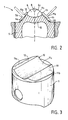
- the piston of each cylinder has an upper diametrical protuberance, comprising two inclined side walls parallel respectively to the inclined walls of the combustion chamber and each cooperating with one intake valves and one of the exhaust valves.
- the upper diametrical protuberance of the piston has a cylindrical upper face forming with the two side walls of them parallel edges facing upwards.
- the combustion chamber comprises on its cylindrical wall and in the center, a petrol injector directed downwards along the axis of the cylinder.
- the cylinder comprises a cylinder head 1 forming a cover at its upper part.
- Two intake pipes 2a and 2b and two exhaust pipes 3a and 3b are connected respectively to two intake valves 4a, 4b and to two exhaust valves 5a and 5b.
- the intake valves 4a, 4b and exhaust 5a, 5b open into a cavity 6 of the cylinder head 1, forming a combustion chamber of the cylinder.
- spark plugs 7a, 7b, diametrically opposite and an injector 8 in the center in the combustion chamber 6 open, in addition, from them spark plugs 7a, 7b, diametrically opposite and an injector 8 in the center.
- the cavity 6 in the cylinder head 1 is in the form of a "roof" having two inclined walls 6a, 6b connected to the top by a cylindrical wall 6c according to a diameter of the cylinder.
- On each of the inclined walls 6a and 6b are mounted respectively an intake valve 4a, 4b and an exhaust valve 5a, 5b.
- the intake valves 4a and 4b are mounted diametrically opposite one another, as are the exhaust valves 5a and 5b.
- the spark plugs 7a, 7b and the injector 8 are mounted on the cylindrical wall 6c at the top of the combustion chamber 6.
- the injector 8 is directed downward along the axis of the cylinder.
- the spark plugs 7a and 7b are preferably slightly inclined relative to the vertical axis of the cylinder.
- valves 4a and 4b open while the piston 9 descends.
- the arrangement of valves 4a and 4b intake generates a strong swirling movement of fresh air around the vertical axis of the cylinder. If the fuel injection takes place during the air intake phase, the fuel mixes homogeneously with the air, due to the central position of the injector. The homogeneity of the mixture is the desired effect to obtain maximum engine performance.
- the piston 9 performs an upward movement.
- the swirling movement of the air is disturbed by the hunting zones of the cylinder head 1 and of the piston 9 which transform the ordered gyration into multiple small local vortices very favorable to combustion, this thanks in part to the edges 12 and 13 of the protrusion 10 of the piston which breaks the vortex movement.
- the flushing movements oppose the free jet of fuel and confine the fuel in the combustion chamber 6 in the vicinity of the ignition plugs 7a and 7b. This has the effect of localized combustion of the rich mixture in the vicinity of the candles, resulting in the formation of very small quantities of nitrogen oxides.
- the invention makes it possible to reduce the petrol consumption of the engine, by optimizing the quantity of petrol injected for combustion.
- the microturbulence movement created in the combustion chamber allows better combustion of the air / petrol mixture and therefore partially reduces the emission of harmful gases during combustion.
- Another case of engine operation may consist in using only two of the four valves, an intake and an exhaust, either by disengaging the unused valves by any means, or by sealing the corresponding conduit with a butterfly valve or a section.
- the valves remaining in service can be either side by side, 5a and 4a or 5b and 4b, or opposite, 5a and 4b or 5b and 4a.
- the example illustrated above relates to a direct injection engine.
- it is possible to produce an indirect injection engine by placing the injector 8 in the air intake pipe 2 upstream of the intake valves 4a, 4b instead of being at the interior of the combustion chamber 6.
- the combustion optimization effect created thanks to the particular structure of the cylinder makes it possible to make significant improvements with respect to conventional indirect injection engines.
- the injection engine according to the invention can operate as an alcohol engine with high efficiency. In this case, it suffices to replace the petrol with an alcohol and inject it via the injectors.
Landscapes
- Engineering & Computer Science (AREA)
- Chemical & Material Sciences (AREA)
- Combustion & Propulsion (AREA)
- Mechanical Engineering (AREA)
- General Engineering & Computer Science (AREA)
- Combustion Methods Of Internal-Combustion Engines (AREA)
Abstract
Le moteur multicylindre à injection d'essence de l'invention comprend, pour chaque cylindre, une chambre de combustion "en toit" (6) constituée de deux parois planes inclinées (6a,6b) raccordées au sommet par une paroi cylindrique (6c) selon un diamètre du cylindre; deux soupapes d'admission (4b) et deux soupapes d'échappement (5b) débouchant dans les parois inclinées de la chambre de combustion et disposées diamétralement opposées l'une à l'autre; deux bougies d'allumage et un injecteur d'essence (8) montés sur la paroi cylindrique (6c) et dirigés vers la chambre de combustion; un piston muni d'une protubérance diamétrale supérieure (10) comportant une gorge cylindrique (11c) délimitée par des arêtes (12,13) formées avec deux parois latérales inclinées (11a,11b) respectivement.
Description
- La présente invention concerne un moteur multicylindre à injection d'essence, muni de quatre soupapes par cylindre, destiné notamment à équiper des véhicules automobiles.
- Le principe de la combustion interne par injection d'essence mélangée avec de l'air dans le moteur, est connu depuis fort longtemps. De tels moteurs peuvent être classés en deux groupes séparés : les moteurs à injection directe et les moteurs à injection indirecte.
- Pour les moteurs à injection directe, l'injection d'essence a lieu à l'intérieur des cylindres en aval de la ou des soupapes d'admission de l'air. Pour les moteurs à injection indirecte, l'injection d'essence a lieu dans la conduite d'admission de l'air du moteur, en amont des soupapes d'admission de l'air, donc en-dehors des cylindres.
- A l'heure actuelle, les moteurs à injection indirecte sont pénalisés par des consommations de carburant importantes à faible charge et des émissions de polluants élevées impliquant un retraitement des gaz d'échappement au moyen d'un coûteux catalyseur. Ces phénomènes sont intimement liés au principe même de la combustion d'un mélange homogène air/essence préparé en amont de ou des soupapes d'admission et à la régulation du couple moteur par réduction de la quantité de mélange admise au moyen d'un papillon obturant une partie du collecteur d'admission. Il résulte de ce procédé des pertes par pompage élevées augmentant les consommations et des émissions de gaz nocifs importantes, surtout lorsque le moteur est peu sollicité.
- Comparativement, les moteurs à injection directe présentent potentiellement de nombreux avantages par rapport aux moteurs à injection indirecte grâce à une stratification de la charge admise dans chaque cylindre. Ce procédé permet ainsi de supprimer le papillon du collecteur d'admission, le couple étant régulé par action sur la quantité d'essence introduite directement dans chaque cylindre, d'où une réduction importante des pertes par pompage. La combustion est parfaitement contrôlée, même pour les très faibles quantités d'essence injectées, du fait de la stratificatirn de la charge, ce qui conduit à fortement limiter les émissions de gaz polluants.
- Des tentatives faites pour un moteur à injection directe dans une préchambre de combustion raccordée par une conduite à la chambre de combustion, n'ont pas donné de résultats satisfaisants, en ce qui concerne notamment l'émission des gaz nocifs.
- La présente invention a pour objet la réalisation d'un moteur multicylindre à injection d'essence, comportant quatre soupapes par cylindre, de structure nouvelle, minimisant des émissions de gaz nocifs à l'échappement, avec un rendement élevé.
- Plus particulièrement, l'invention a pour object un moteur à injection directe pour véhicule automobile.
- L'invention a également pour object un moteur à injection indirecte pour automobile.
- Le moteur multicylindre à injection d'essence, selon l'invention, comprend des moyens d'admission de l'air, des moyens d'échappement de gaz après combustion, des moyens d'injection de l'essence et des moyens d'allumage du mélange air/essence dans la chambre de combustion des cylindres.
- Selon l'invention, le moteur comprend pour chacun de ses cylindres :
- une culasse formant couvercle dans la partie supérieure du cylindre et munie d'une chambre de combustion "en toit" constituée de deux parois planes inclinées se rejoignant au somment par une paroi sensiblement cylindrique selon un diamètre du cylindre;
- deux soupapes d'admission et deux soupapes d'échappement, débouchant perpendiculairement, et regroupées par deux, dans les parois inclinées de la chambre de combustion, les soupapes d'admission et les soupapes d'échappement étant disposées, respectivement, diamétralement oposées l'une à l'autre;
- deux bougies débouchant dans la paroi cylindrique au sommet de la chambre de combustion et dirigées de façon inclinée vers l'intérieur de la chambre de combustion. - Selon l'invention, le piston de chaque cylindre présente une protubérance diamétrale supérieure, comportant deux parois latérales inclinées parallèles respectivement aus parois inclinées de la chambre de combustion et coopérant chacune avec l'une des soupapes d'admission et l'une des soupapes d'échappement.
- Selon un mode préféré de réalisation de l'invention, la protubérance diamétrale supérieure du piston présente une face supérieure cylindrique formant avec les deux parois latérales d'eux arêtes parallèles orientées vers le haut.
- Selon un mode particulier de l'invention, la chambre de combustion comporte sur sa paroi cylindrique et au centre, un injecteur d'essence dirigé vers le bas selon l'axe du cylindre.
- L'invention sera mieux comprise à l'étude de la description détaillée d'un mode de réalisation particulier de l'invention, pris à titre nullement limitafif et illustré par les dessins annexés, sur lesquels :
- la figure 1 est une vue schématique de la culasse du côté inférieur selon l'invention;
- la figure 2 est une vue schématique en coupe selon II-II de la figure 1, représentant la chambre de combustion lorsque le piston est à son point mort haut; et
- la figure 3 est une vue en perspective du piston de la figure 2.
- Sur les figures, est représenté un cylindre unique pour expliquer le fonctionnement du moteur de la présente invention, les autres cylindres du moteur fonctionnant de manière identique à celui illustré.
- Tel qu'il est illustré sur la figure 1, le cylindre comprend une culasse 1 formant couvercle à sa partie supérieure. Deux conduites d'admission 2a et 2b et deux conduites d'échappement 3a et 3b sont connectées respectivement à deux soupapes d'admission 4a,4b et à deux soupapes d'échappement 5a et 5b. Les soupapes d'admission 4a,4b et d'échappement 5a,5b débouchent dans une cavité 6 de la culasse 1, formant une chambre de combustion du cylindre. Dans la chambre de combustion 6 débouchent, en outre, d'eux bougies d'allumage 7a,7b, diamétralement opposées et un injecteur 8 au centre.
- Comme représenté sur la figure 2, la cavité 6 dans la culasse 1 est sous forme d'un "toit" comportant deux parois inclinées 6a,6b raccordées au sommet par une paroi cylindrique 6c selon un diamètre du cylindre. Sur chacune des parois inclinées 6a et 6b, sont montées respectivement une soupape d'admission 4a,4b et une soupape d'échappement 5a,5b. Les soupapes d'admission 4a et 4b sont montées diamétralement opposées l'une à l'autre, ainsi que les soupapes d'échappement 5a et 5b.
- Les bougies d'allumage 7a,7b ainsi que l'injecteur 8, sont montés sur la paroi cylindrique 6c au sommet de la chambre de combustion 6. L'injecteur 8 est dirigé vers le bas selon l'axe du cylindre. Les bougies d'allumage 7a et 7b sont de préférence légèrement inclinées par rapport à l'axe vertical du cylindre.
- La figure 3 montre un piston 9 qui comporte une protubérance diamétrale supérieure 10. La protubérance 10 présente deux parois latérales 11a et 11b parallèles respectivement aux parois inclinées 6a et 6b de la chambre de combustion 6. La face supérieure 11c de la protubérance 10 est cylindrique et forme avec les parois latérales 11a et 11b deux arêtes 12 et 13 parallèles orientées vers le haut. Les dimensions de la protubérance 10 étant telles que, lorsque le piston arrive à son point mort haut, la protubérance 10 du piston 9 entre dans la cavité 6 de la culasse 1 avec de faibles entrefers entre les deux pièces.
- Lors de la phase d'admission de l'air, les soupapes d'admission 4a et 4b s'ouvrent pendant que le piston 9 descend. La disposition des soupapes d'admission 4a et 4b génère un fort mouvement tourbillonnaire de l'air frais autour de l'axe vertical du cylindre. Si l'injection de carburant a lieu pendant la phase d'admission de l'air, le carburant se mélange de manière homogène avec l'air, du fait de la position centrale de l'injecteur. L'homogénéité du mélange est l'effet recherché pour obtenir des performances maximales du moteur.
- Durant la phase de compression, le piston 9 effectue un mouvement ascendant. Le mouvement tourbillonnaire de l'air est perturbé par des zones de chasse de la culasse 1 et du piston 9 qui transforment la giration ordonnée en de multiples petits vortex locaux très favorables à la combustion, cela grâce en partie aux arêtes 12 et 13 de la protubérance 10 du piston qui brisent le mouvement tourbillonnaire. Si l'injection de carburant a lieu durant cette phase, les mouvements de chasse s'opposent au jet libre du carburant et confinent le carburant dans la chambre de combustion 6 au voisinage des brugies d'allumage 7a et 7b. Ce qui a pour effet une combustion localisée du mélange riche au voisinage des bougies, d'où formation de très faibles quantités d'oxydes d'azote.
- L'air n'ayant pas participé à la combustion permet d'oxyder des gaz nocifs de combustion, notamment des hydrocarbures et le monooxyde de carbone. Il en résulte une réduction d'émission des gaz nocifs à l'échappement et donc une augmentation de la propreté du moteur. De tels fonctionnements sont très recherchés pour assurer le régime de faible charge du moteur, notamment pour des circulations urbaines.
- En outre, l'invention permet de réduire la consommation en essence du moteur, grâce à l'optimisation de la quantité d'essence injectée pour la combustion. Le mouvement de microturbulence créé dans la chambre de combustion permet une meilleure combustion du mélange air/essence et donc de réduire en partie l'émission de gaz nocifs pendant la combustion.
- Un autre cas de fonctionnement du moteur peut consister à n'utiliser que deux des quatre soupapes, une d'admission et une d'échappement, soit en débrayant par un moyen quelconque les soupapes inutilisées, soit en obturant le conduit correspondant par un papillon ou un volet. Les d'eux soupapes restant en service peuvent être, soit côte à côte, 5a et 4a ou 5b et 4b, soit opposées, 5a et 4b ou 5b et 4a. Ce cas de figure permet d'e réduire la quantité d'air admise dans chaque cylindre, de modifier les mouvements d'air créés lors de la phase d'admission et l'acoustique du collecteur d'admission en fonction du couple et du régime réclamés par le conducteur du véhicule automobile.
- L'exemple illustré précédemment se rapporte à un moteur à injection directe. Il est possible de réaliser, selon l'invention, un moteur à injection indirecte en plaçant l'injecteur 8 dans la conduite d'admission de l'air 2 en amont des soupapes d'admission 4a,4b au lieu d'être à l'intérieur de la chambre de combustion 6. L'effet d'optimisation de la combustion créé grâce à la structure particulière du cylindre, permet d'apporter des améliorations importantes vis-à-vis des moteurs à injection indirecte classique.
- Il est à noter également que le moteur à injection, selon l'invention, peut fonctionner comme un moteur à alcools avec un rendement élevé. Dans ce cas, il suffit de remplacer l'essence par un alcool et de l'injecter par l'intermédiaire des injecteurs.
Claims (5)
1. Moteur multicylindre à injection de carburant, notamment d'essence, comprenant des moyens d'admission de l'air, des moyens d'échappement de gaz après combustion, des moyens d'injection de l'essence et des moyens d'allumage ; une culasse (1) munie d'une cavité (6) formant chambre de combustion "en toit" constituée de deux parois planes inclinées (6a, 6b) se rejoignant au sommet par une paroi sensiblement cylindrique (6c) selon un diamètre du cylindre ; deux soupapes d'admission (4a, 4b) et deux soupapes d'échappement (5a, 5b) débouchant dans les parois inclinées de la chambre de combustion, et disposées, respectivement, diamétralement opposées l'une à l'autre ; caractérisé en ce qu'il comprend pour chaque cylindre , deux bougies (7a, 7b) débouchant dans la paroi cylindrique au sommet de la chambre de combustion et orientées de façon inclinée par rapport à l'axe vertical du cylindre.
2. Moteur multicylindre à injection selon la revendication 1, caractérisé par le fait que le piston (9) du cylindre comporte une protubérance diamétrale supérieure (10) munie de deux parois latérales inclinées (11a, 11b) parallèles respectivement aux parois inclinées de la chambre de combustion.
3. Moteur multicylindre à injection selon la revendicatin 2, caractérisé par le fait que la face supérieure (11c) de la protubérance est sous forme cylindrique, raccordant respectivement les deux parois latérales (11a, 11b) pour former deux aretes parallèles (12, 13) dirigées vers le haut.
4. Moteur multicylindre à injection selon l'une quelconque des revendications précédentes, caractérisé par le fait qu'il comporte pour chaque cylindre un injecteur (8) dans la paroi cylindrique (6c) de la chambre de combustion (6).
5. Moteur multicylindre à injection selon la revendication 4, caractérisé par le fait que l'injecteur (8) est monté au centre de la chambre de combustion (6) set dirigé vers le bas selon l'axe du cylindre.
Applications Claiming Priority (2)
| Application Number | Priority Date | Filing Date | Title |
|---|---|---|---|
| FR8910441 | 1989-08-02 | ||
| FR8910441A FR2650630A1 (fr) | 1989-08-02 | 1989-08-02 | Moteur multicylindre a injection d'essence, comportant quatre soupapes par cylindre |
Publications (1)
| Publication Number | Publication Date |
|---|---|
| EP0412008A1 true EP0412008A1 (fr) | 1991-02-06 |
Family
ID=9384421
Family Applications (1)
| Application Number | Title | Priority Date | Filing Date |
|---|---|---|---|
| EP90402202A Ceased EP0412008A1 (fr) | 1989-08-02 | 1990-08-01 | Moteur multicylindre à injection d'essence, comportant quatre soupapes par cylindre |
Country Status (2)
| Country | Link |
|---|---|
| EP (1) | EP0412008A1 (fr) |
| FR (1) | FR2650630A1 (fr) |
Cited By (17)
| Publication number | Priority date | Publication date | Assignee | Title |
|---|---|---|---|---|
| EP0768457A1 (fr) * | 1995-10-13 | 1997-04-16 | Institut Français du Pétrole | Moteur à combustion interne à quatre temps et à allumage commandé et injection directe de carburant |
| AT1562U1 (de) * | 1996-08-30 | 1997-07-25 | Avl Verbrennungskraft Messtech | Viertakt-brennkraftmaschine mit fremdzündung |
| EP0778403A4 (fr) * | 1995-03-28 | 1998-02-11 | Mitsubishi Motors Corp | Moteur a combustion interne du type a injection dans le cylindre |
| WO1998012426A1 (fr) * | 1996-09-18 | 1998-03-26 | Robert Bosch Gmbh | Moteur a combustion interne |
| EP0835994A3 (fr) * | 1996-10-08 | 1998-06-17 | Fuji Jukogyo Kabushiki Kaisha | Chambre de combustion |
| US5806482A (en) * | 1995-03-28 | 1998-09-15 | Mitsubishi Jidosha Kogyo Kabushiki Kaisha | In-cylinder injection internal combustion engine |
| EP0851102A3 (fr) * | 1996-12-24 | 1999-04-07 | Toyota Jidosha Kabushiki Kaisha | Chambre de combustion pour moteur à combustion interne |
| FR2770256A1 (fr) * | 1997-10-24 | 1999-04-30 | Renault | Moteur a injection directe et allumage commande |
| FR2783566A1 (fr) * | 1998-09-23 | 2000-03-24 | Renault | Moteur a combustion interne a allumage commande |
| US6047592A (en) * | 1996-04-01 | 2000-04-11 | Avl List Gmbh | Four-stroke internal combustion engine with spark ignition |
| EP1063398A3 (fr) * | 1997-05-20 | 2001-01-03 | Nissan Motor Co., Ltd. | Piston pour moteur à essence à injection directe |
| DE4129804C2 (de) * | 1991-09-07 | 2002-11-28 | Porsche Ag | Brennraum eines Hubkolbenmotors |
| EP1191198A3 (fr) * | 2000-09-20 | 2003-03-12 | Yamaha Hatsudoki Kabushiki Kaisha | Moteur à combustion interne avec injection de carburant centrale et méthode d'injection de carburant dans un moteur de type d'injection centrale |
| FR2849901A1 (fr) * | 2003-01-13 | 2004-07-16 | Renault Sa | Cylindre pour moteur a combustion interne et allumage par compression et moteur comprenant un tel cylindre |
| WO2006048128A1 (fr) * | 2004-11-03 | 2006-05-11 | Daimlerchrysler Ag | Chambre de combustion d'un moteur a combustion interne a injection directe |
| WO2006048129A1 (fr) * | 2004-11-03 | 2006-05-11 | Daimlerchrysler | Moteur a combustion interne |
| WO2006079369A1 (fr) * | 2004-11-03 | 2006-08-03 | Daimlerchrysler Ag | Conception de chambre de combustion d'un moteur a combustion interne a injection directe |
Families Citing this family (1)
| Publication number | Priority date | Publication date | Assignee | Title |
|---|---|---|---|---|
| TWI711767B (zh) * | 2019-06-21 | 2020-12-01 | 王鼎瑞 | 扣體與組裝方法 |
Citations (4)
| Publication number | Priority date | Publication date | Assignee | Title |
|---|---|---|---|---|
| DE1919323A1 (de) * | 1969-04-16 | 1971-01-14 | Bayerische Motoren Werke Ag | Zylinderkopf fuer Brennkraftmaschinen |
| DE2704721A1 (de) * | 1976-02-06 | 1977-08-11 | Nissan Motor | Brennkraftmaschine |
| US4162661A (en) * | 1977-02-25 | 1979-07-31 | Toyota Jidosha Kogyo Kabushiki Kaisha | Internal combustion engine with combustion chambers which create a squish and swirl of an air-fuel mixture |
| US4445467A (en) * | 1982-08-10 | 1984-05-01 | Howard Westerman | Two-cycle stratified charge gas engine |
Family Cites Families (1)
| Publication number | Priority date | Publication date | Assignee | Title |
|---|---|---|---|---|
| JPS6060215A (ja) * | 1983-09-09 | 1985-04-06 | Daihatsu Motor Co Ltd | 内燃機関 |
-
1989
- 1989-08-02 FR FR8910441A patent/FR2650630A1/fr not_active Withdrawn
-
1990
- 1990-08-01 EP EP90402202A patent/EP0412008A1/fr not_active Ceased
Patent Citations (4)
| Publication number | Priority date | Publication date | Assignee | Title |
|---|---|---|---|---|
| DE1919323A1 (de) * | 1969-04-16 | 1971-01-14 | Bayerische Motoren Werke Ag | Zylinderkopf fuer Brennkraftmaschinen |
| DE2704721A1 (de) * | 1976-02-06 | 1977-08-11 | Nissan Motor | Brennkraftmaschine |
| US4162661A (en) * | 1977-02-25 | 1979-07-31 | Toyota Jidosha Kogyo Kabushiki Kaisha | Internal combustion engine with combustion chambers which create a squish and swirl of an air-fuel mixture |
| US4445467A (en) * | 1982-08-10 | 1984-05-01 | Howard Westerman | Two-cycle stratified charge gas engine |
Non-Patent Citations (1)
| Title |
|---|
| PATENT ABSTRACTS OF JAPAN vol. 9, no. 194 (M-403)(1917) 10 août 1985, & JP-A-60 060215 (DAIHATSU KOGYO KK) 06 avril 1985, * |
Cited By (24)
| Publication number | Priority date | Publication date | Assignee | Title |
|---|---|---|---|---|
| DE4129804C2 (de) * | 1991-09-07 | 2002-11-28 | Porsche Ag | Brennraum eines Hubkolbenmotors |
| EP0778403A4 (fr) * | 1995-03-28 | 1998-02-11 | Mitsubishi Motors Corp | Moteur a combustion interne du type a injection dans le cylindre |
| US5806482A (en) * | 1995-03-28 | 1998-09-15 | Mitsubishi Jidosha Kogyo Kabushiki Kaisha | In-cylinder injection internal combustion engine |
| EP0768457A1 (fr) * | 1995-10-13 | 1997-04-16 | Institut Français du Pétrole | Moteur à combustion interne à quatre temps et à allumage commandé et injection directe de carburant |
| US5709189A (en) * | 1995-10-13 | 1998-01-20 | Institut Francais Du Petrole | Controlled-ignition direct fuel injection four-cycle internal combustion engine |
| FR2739895A1 (fr) * | 1995-10-13 | 1997-04-18 | Inst Francais Du Petrole | Moteur a combustion interne a quatre temps et a allumage commande et injection directe de carburant |
| US6047592A (en) * | 1996-04-01 | 2000-04-11 | Avl List Gmbh | Four-stroke internal combustion engine with spark ignition |
| AT1562U1 (de) * | 1996-08-30 | 1997-07-25 | Avl Verbrennungskraft Messtech | Viertakt-brennkraftmaschine mit fremdzündung |
| WO1998012426A1 (fr) * | 1996-09-18 | 1998-03-26 | Robert Bosch Gmbh | Moteur a combustion interne |
| EP0835994A3 (fr) * | 1996-10-08 | 1998-06-17 | Fuji Jukogyo Kabushiki Kaisha | Chambre de combustion |
| EP0851102A3 (fr) * | 1996-12-24 | 1999-04-07 | Toyota Jidosha Kabushiki Kaisha | Chambre de combustion pour moteur à combustion interne |
| USRE37714E1 (en) | 1996-12-24 | 2002-05-28 | Toyota Jidosha Kabushiki Kaisha | Combustion chamber structure for an internal combustion engine |
| EP1063398A3 (fr) * | 1997-05-20 | 2001-01-03 | Nissan Motor Co., Ltd. | Piston pour moteur à essence à injection directe |
| US6253728B1 (en) | 1997-05-20 | 2001-07-03 | Nissan Motor Co., Ltd. | Direct injection gasoline engine with stratified charge combustion and homogeneous charge combustion |
| FR2770256A1 (fr) * | 1997-10-24 | 1999-04-30 | Renault | Moteur a injection directe et allumage commande |
| WO1999022125A1 (fr) * | 1997-10-24 | 1999-05-06 | Renault | Moteur a injection directe et allumage commande |
| WO2000017505A1 (fr) * | 1998-09-23 | 2000-03-30 | Renault | Moteur a combustion interne a allumage commande |
| FR2783566A1 (fr) * | 1998-09-23 | 2000-03-24 | Renault | Moteur a combustion interne a allumage commande |
| EP1191198A3 (fr) * | 2000-09-20 | 2003-03-12 | Yamaha Hatsudoki Kabushiki Kaisha | Moteur à combustion interne avec injection de carburant centrale et méthode d'injection de carburant dans un moteur de type d'injection centrale |
| FR2849901A1 (fr) * | 2003-01-13 | 2004-07-16 | Renault Sa | Cylindre pour moteur a combustion interne et allumage par compression et moteur comprenant un tel cylindre |
| WO2006048128A1 (fr) * | 2004-11-03 | 2006-05-11 | Daimlerchrysler Ag | Chambre de combustion d'un moteur a combustion interne a injection directe |
| WO2006048129A1 (fr) * | 2004-11-03 | 2006-05-11 | Daimlerchrysler | Moteur a combustion interne |
| WO2006079369A1 (fr) * | 2004-11-03 | 2006-08-03 | Daimlerchrysler Ag | Conception de chambre de combustion d'un moteur a combustion interne a injection directe |
| US7506631B2 (en) | 2004-11-03 | 2009-03-24 | Daimler Ag | Internal combustion engine |
Also Published As
| Publication number | Publication date |
|---|---|
| FR2650630A1 (fr) | 1991-02-08 |
Similar Documents
| Publication | Publication Date | Title |
|---|---|---|
| EP0412008A1 (fr) | Moteur multicylindre à injection d'essence, comportant quatre soupapes par cylindre | |
| US5915351A (en) | Insulated precombustion chamber | |
| EP1217186B1 (fr) | Moteur à injection directe pourvu d'un faible angle de nappe et procédés permettant d'utiliser un tel moteur | |
| US5778849A (en) | Insulated precombustion chamber | |
| US4133322A (en) | Internal combustion engine | |
| US4237826A (en) | Multi-cylinder internal combustion engine equipped with an accumulation chamber | |
| EP0412009A1 (fr) | Moteur multicylindre à injection d'essence, comportant trois soupapes par cylindre | |
| EP3788243B1 (fr) | Dispositif d'admission de gaz avec une intersection du conduit d'admission et de la calibration de soupape inclinee par rapport a la face feu | |
| FR3071880B1 (fr) | Moteur a combustion interne avec injection directe de carburant dans le sens du mouvement des gaz d'admission | |
| EP3914818B1 (fr) | Conduit d'admission de gaz générant un mouvement aérodynamique du gaz au sein d'un cyclindre | |
| EP0425327A1 (fr) | Injecteur électromagnétique d'un fluide gazeux pour moteur à combustion interne | |
| FR2926849A1 (fr) | Moteur thermique de vehicule automobile a chambres de combustion de rendement eleve. | |
| EP0686760B1 (fr) | Moteur à combustion interne à plusieurs soupapes d'admission par cylindre | |
| EP1861596B1 (fr) | Moteur a combustion interne, notamment a injection directe, avec un piston muni d'un bol comprenant un teton | |
| GB1581689A (en) | Internal combustion engine | |
| FR3071878B1 (fr) | Chambre de combustion de forme elliptique | |
| RU2119066C1 (ru) | Способ работы двигателя внутреннего сгорания | |
| FR2818324A1 (fr) | Moteur a injection directe, pourvu d'un injecteur a faible angle de nappe | |
| FR2853358A1 (fr) | Moteur a combustion interne a essence et a auto-allumage | |
| FR2712028A1 (fr) | Moteur à combustion interne à injection indirecte de carburant. | |
| FR2878906A1 (fr) | Moteur a injection directe de carburant avec un piston comportant un bol presentant une paroi laterale inclinee | |
| FR2756589A1 (fr) | Moteur a combustion interne a allumage par compression et a injection directe | |
| FR2885391A1 (fr) | Moteur a combustion interne de vehicule automobile a injection directe, notamment de type diesel | |
| FR2888878A3 (fr) | Dispositif d'admission pour moteur a combustion interne | |
| FR2835879A1 (fr) | Moteur a combustion interne a allumage par compression |
Legal Events
| Date | Code | Title | Description |
|---|---|---|---|
| PUAI | Public reference made under article 153(3) epc to a published international application that has entered the european phase |
Free format text: ORIGINAL CODE: 0009012 |
|
| AK | Designated contracting states |
Kind code of ref document: A1 Designated state(s): DE GB IT |
|
| 17P | Request for examination filed |
Effective date: 19910710 |
|
| 17Q | First examination report despatched |
Effective date: 19920615 |
|
| STAA | Information on the status of an ep patent application or granted ep patent |
Free format text: STATUS: THE APPLICATION HAS BEEN REFUSED |
|
| 18R | Application refused |
Effective date: 19940106 |