EP0412212A1 - Clapet électromagnétique pour fluide liquide ou gazeux et sa commande - Google Patents
Clapet électromagnétique pour fluide liquide ou gazeux et sa commande Download PDFInfo
- Publication number
- EP0412212A1 EP0412212A1 EP89307999A EP89307999A EP0412212A1 EP 0412212 A1 EP0412212 A1 EP 0412212A1 EP 89307999 A EP89307999 A EP 89307999A EP 89307999 A EP89307999 A EP 89307999A EP 0412212 A1 EP0412212 A1 EP 0412212A1
- Authority
- EP
- European Patent Office
- Prior art keywords
- valve
- control piston
- solenoid valve
- armature
- valve according
- Prior art date
- Legal status (The legal status is an assumption and is not a legal conclusion. Google has not performed a legal analysis and makes no representation as to the accuracy of the status listed.)
- Withdrawn
Links
- 239000007788 liquid Substances 0.000 title claims description 8
- 239000012530 fluid Substances 0.000 title 1
- 238000004804 winding Methods 0.000 claims description 8
- 239000000463 material Substances 0.000 claims description 6
- 238000005260 corrosion Methods 0.000 claims description 5
- 230000007797 corrosion Effects 0.000 claims description 5
- 238000000034 method Methods 0.000 claims description 5
- 239000002184 metal Substances 0.000 claims description 3
- 238000007789 sealing Methods 0.000 description 4
- 238000000418 atomic force spectrum Methods 0.000 description 3
- 238000005516 engineering process Methods 0.000 description 3
- 125000006850 spacer group Chemical group 0.000 description 3
- 230000007423 decrease Effects 0.000 description 2
- 238000010586 diagram Methods 0.000 description 2
- 230000003068 static effect Effects 0.000 description 2
- 230000006835 compression Effects 0.000 description 1
- 238000007906 compression Methods 0.000 description 1
- 230000002349 favourable effect Effects 0.000 description 1
- 230000003993 interaction Effects 0.000 description 1
- 238000004519 manufacturing process Methods 0.000 description 1
- 239000011347 resin Substances 0.000 description 1
- 229920005989 resin Polymers 0.000 description 1
- 230000000717 retained effect Effects 0.000 description 1
- 229910001220 stainless steel Inorganic materials 0.000 description 1
- 239000010935 stainless steel Substances 0.000 description 1
- 230000007704 transition Effects 0.000 description 1
- XLYOFNOQVPJJNP-UHFFFAOYSA-N water Substances O XLYOFNOQVPJJNP-UHFFFAOYSA-N 0.000 description 1
Images

Classifications
-
- F—MECHANICAL ENGINEERING; LIGHTING; HEATING; WEAPONS; BLASTING
- F16—ENGINEERING ELEMENTS AND UNITS; GENERAL MEASURES FOR PRODUCING AND MAINTAINING EFFECTIVE FUNCTIONING OF MACHINES OR INSTALLATIONS; THERMAL INSULATION IN GENERAL
- F16K—VALVES; TAPS; COCKS; ACTUATING-FLOATS; DEVICES FOR VENTING OR AERATING
- F16K31/00—Actuating devices; Operating means; Releasing devices
- F16K31/02—Actuating devices; Operating means; Releasing devices electric; magnetic
- F16K31/06—Actuating devices; Operating means; Releasing devices electric; magnetic using a magnet, e.g. diaphragm valves, cutting off by means of a liquid
- F16K31/0675—Electromagnet aspects, e.g. electric supply therefor
- F16K31/0679—Electromagnet aspects, e.g. electric supply therefor with more than one energising coil
-
- F—MECHANICAL ENGINEERING; LIGHTING; HEATING; WEAPONS; BLASTING
- F16—ENGINEERING ELEMENTS AND UNITS; GENERAL MEASURES FOR PRODUCING AND MAINTAINING EFFECTIVE FUNCTIONING OF MACHINES OR INSTALLATIONS; THERMAL INSULATION IN GENERAL
- F16K—VALVES; TAPS; COCKS; ACTUATING-FLOATS; DEVICES FOR VENTING OR AERATING
- F16K11/00—Multiple-way valves, e.g. mixing valves; Pipe fittings incorporating such valves
- F16K11/02—Multiple-way valves, e.g. mixing valves; Pipe fittings incorporating such valves with all movable sealing faces moving as one unit
- F16K11/04—Multiple-way valves, e.g. mixing valves; Pipe fittings incorporating such valves with all movable sealing faces moving as one unit comprising only lift valves
- F16K11/044—Multiple-way valves, e.g. mixing valves; Pipe fittings incorporating such valves with all movable sealing faces moving as one unit comprising only lift valves with movable valve members positioned between valve seats
Definitions
- the invention relates to a solenoid valve for a liquid or gaseous medium and a method for controlling a solenoid valve which can be used in automated systems, in particular in offshore technology, to start, stop or redirect the medium flow.
- the electromagnet is the most common actuating element of valves, especially in stationary devices, while mechanical actuation via buttons or fog is the most common type of actuation in mobile devices.
- Solenoid valves with two switching positions are usually actuated against a return spring, which keeps the valve in the zero position as long as no actuating force acts. Valves with locking in every switching position are also known. With solenoid valves, it is possible to lock the version with two switch positions. If both switching positions are brought about by electromagnets, the last switched position is retained even if the electrical control voltage fails. Because of the latching, an electrical control pulse is sufficient for actuation. In order to achieve sufficient actuating forces, current pulses with relatively large energy are selected for the generation of the control pulses. Therefore, powerful, heavy-duty electric batteries must be used for power supply in remote-controlled devices for controlling solenoid valves.
- the invention has for its object to provide a solenoid valve and a method for controlling such a valve, in which very short with an electrical control pulse Duration and low power sufficient actuating forces can be achieved to actuate the solenoid valve, so that even when using electrical supply voltage sources of smaller size and power, safe operation of a solenoid valve is possible. Furthermore, the solenoid valve should also allow direct control of a medium with a relatively high pressure.
- a solenoid valve for a liquid or gaseous medium in which a control piston is movably arranged in two switching positions in a valve chamber, which is connected via a valve tappet with the interposition of a spring with an armature, which an electromagnet for switching from one Switch position in the other and means for locking the control piston in at least one switching position are assigned.
- valve body from a corrosion-resistant material and to accommodate the electromagnet in a corrosion-resistant housing which is attached to the valve body on the end face.
- a corrosion-resistant housing which is attached to the valve body on the end face.
- Such a solenoid valve can also be used underwater in offshore technology.
- the electromagnet is advantageously formed by two pot cores arranged coaxially in the housing, the openings of which with the interposition of the armature facing each other and the middle legs are each provided with at least one electrical winding and a central bore into which the valve tappet is inserted and in which the armature is movably guided, which is arranged axially displaceably mounted on the valve tappet between two springs.
- the end region of the valve tappet facing the armature has a threaded bore into which a screw is screwed, on which the armature is axially displaceably mounted between the two springs.
- the threaded bore can be arranged in an adjusting sleeve which is screwed into an external thread at the end region of the valve tappet. In this way, simple adjustment of the armature relative to the control piston is possible.
- the means for locking the control piston can, according to the invention, be formed by an actuating piston axially connected to the control piston, which is guided in a cylinder which connects to the valve chamber into which the medium to be controlled is introduced, the inner diameter of the opening of an outer one Valve seat is smaller than that of the cylinder seal. In this way, the control piston is held against the outer valve seat by the pressure of the medium to be controlled (the valve is closed).
- Hydraulically locked valves can no longer maintain their position if the supply pressure is lost. According to an advantageous development of the invention, this is achieved by arranging an additional spring which holds the control piston in a predetermined position or in a position on the valve seat from which it would detach itself.
- the additional spring is preferably arranged coaxially to the valve tappet between the bottom of the valve body and the control piston. In this way, hydraulic locking becomes effective, not only as long as the supply pressure is present is sufficient, but also if the valve should assume a predetermined position, in particular a closed position, when the supply pressure drops to the ambient pressure.
- the spring located between the armature and the valve lifter may be biased so that the spool is held in position by a combination of the spring pressure and the imbalance of forces due to the smaller inner diameter of the outer valve seat and the larger inner diameter of the actuating piston or the associated cylinder seal are generated.
- the means for locking the control piston can also be formed by an actuating piston axially connected to the control piston, which is guided in a cylinder which connects to the valve chamber into which the medium to be controlled is introduced, the inner diameter of the opening of an inner Valve seat is slightly larger than that of the cylinder seal. As a result, the control piston is pressed against the inner valve seat as long as the supply pressure is present (the valve is open and the medium flows into the working line).
- the slider can be automatically locked in any switching position without additional mechanical locking parts by the controlled medium.
- the cylinder can have a cylinder seal, which is expediently designed as a lip seal. In this way, breakaway forces when changing the valve, the friction and leakage losses are kept low. It is also possible to arrange an annular seal on the actuating piston, which is designed as a profile seal.
- the invention also relates to a method for controlling a solenoid valve for a liquid or gaseous medium, in which, according to the invention, an electrical control pulse is applied to a winding of an electromagnet to which an armature is assigned, a spring being tensioned by the movement of the armature, the tensioned spring moves a control piston arranged in a valve chamber with two switching positions from one switching position to the other, and the control piston is locked in the switching position reached.
- the directional control valve can be used as a pilot valve for a hydraulically operated directional control valve. It has the task of optionally controlling a medium on one of the two sides of the hydraulically operated directional valve.
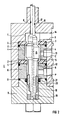
- a valve body 1 has a bore 2, which has an inner valve seat 3, an inner spacer 4, an outer Valve seat 5 and an outer spacer 6 receives.
- two further, smaller bores 7, 8 are made in alignment with the longitudinal axis of the valve body 1.
- the valve inserts 3, 4, 5, 6 are held in the valve body 1 by a cover 9 with an inner flange.
- the cover 9 has a blind hole 10.
- annular recesses are provided, in which a sealing ring 11, in particular an O-ring, is attached.
- a sealing ring 11 in particular an O-ring
- the valve interior is divided into three chambers 12, 13, 14 and each chamber is provided with a valve connection P or C or R through a radial bore.
- An inlet line is connected to the valve connection P, a discharge or working line to the valve connection C and a return line for the medium to the valve connection R.
- a control piston 15 is arranged in the valve chamber 13, on one side of which a valve tappet 16 guided in the bore 8 is arranged, which can be actuated by an electromagnet 22.
- the control piston 15 is axially movably guided in a bearing 19 via a pin 18. This bearing 19 is arranged in the blind hole 10. Precautions have been taken to prevent the spool from rotating.
- an actuating piston 20 Arranged between the pin 18 and the control piston 15 is an actuating piston 20 which projects into the blind hole 10 serving as a cylinder and to which a cylinder seal 21 is assigned at the opening of the blind hole.
- This cylinder seal 21 is advantageously designed as a lip seal. Bores 20a to 20c lead from the head of the actuating piston 20 to the chamber 14.
- the electromagnet 22 used to actuate the control piston 15 is attached to the valve body 1 at the end. It is formed by two pot cores 24, 25 arranged coaxially in a corrosion-resistant housing, the openings 26, 27 of which face one another with the interposition of an armature 28. A separately controllable electrical winding 31, 32 or a plurality of partial windings is arranged on each of the middle legs 29, 30. The windings are cast in resin. The central legs 29, 30 also each have a central bore 33. The valve lifter 16 is inserted into these bores 33.
- the armature 28 is clamped between two springs 35, 36 designed as plate springs and is axially displaceably mounted on the valve tappet 16.
- the end region of the valve tappet 16 facing the armature 28 has a threaded bore 37a into which a screw 38 designed as a cylinder head screw is screwed with its threaded end and slidably supports the armature 28 between the two springs 35, 36.
- the armature 28, which is designed as a disk and made of a ferritic material, has a central bearing sleeve 40 which projects into the central bores 33 of the pot cores on both sides.
- the threaded bore 37a is made in an adjusting sleeve 37 which is screwed into an external thread 41 at the end of the valve lifter 16.
- the adjusting sleeve 37 is rotated on the end of the valve lifter 16 provided with the thread 41.
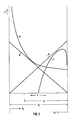
- the force F is plotted on the coordinate and paths x1 - x4 on the abscissa.
- x1 stroke of the control piston x2 stroke of the anchor x3 distance of the armature from the magnetic core x4 distance of the spool from the initial position.
- Curve a shows the force curve on the armature 28 of the magnet.
- the force has its maximum when the armature 28 bears against the magnetic core 24 or 25. It decreases steeply with distance. The decrease is so rapid that if the armature were connected directly to the control piston, the force of the magnet used would not be sufficient to lift the control piston 15 from the seat.
- Curve b shows the force required to compress springs 35 and 36, respectively. If this compression is to be carried out by the electromagnet, curve b must lie completely below curve a.
- Curve c shows the force curve that is required to move the control piston.
- the maximum force required occurs when the control piston 15 has broken loose from its seat and results from the hydraulic forces (resulting from the transition of the delivery pressure to the dynamic pressure) which are added to the static latching and frictional forces. The force then drops sharply because the static friction changes into dynamic friction and the flow changes. In theory, if no friction is assumed and the spool is half the way, no force is required to move it, because the spool is then moved by the hydraulic forces.
- Curve d shows the force available from springs 35 and 36, respectively, to move the spool.
- the force curve is inverse to curve b.
- Fig. 2 shows an enlarged section through the valve body 1 in two positions of the control piston 15.
- the left half of the section shows the open position of the valve, in which the medium via the inlet channel P (supply) into the valve chamber and from there via the open control piston in the chamber 13 can get from where it flows via the discharge connection C (service) into a working line.
- the control piston 15 is moved between the two positions shown by an adjusting force which emanates from the electromagnet 22.
- the inner diameters of the inner and outer valve seat and the cylinder seal 21 are matched to one another in such a way that a differential force occurs in the desired direction.
- a force is generated which holds the control piston 15 on the inner valve seat 3 when the valve is open.
- the inner diameter of the outer valve seat 5 has a smaller value than the cylinder seal 21, so that the resulting force holds the control piston 15 on the outer valve seat 5, the valve is closed.
- Both the outer and the inner valve seat are made of plastic material, while the remaining valve parts are made of metal, preferably stainless steel. This can significantly reduce the stress required to achieve a 100% seal on the inside diameter of the valve seats over a metal-to-metal seal. This is important because the electromagnet has to overcome the hydraulic locking forces, which should therefore be kept as small as possible.
- the forces which the electromagnet has to overcome have three essentially identical causes, namely the latching forces, the sealing friction and the hydraulic flow forces.
- the locking forces have already been mentioned and can be minimized by using suitable plastic material for the valve seats.
- the seal friction has two causes: the cylinder seal 21 and the ring seal 17 of the valve lifter 16.
- the cylinder seal 21 is always exposed to the pressure of the feed line and can generate considerable frictional forces.
- a seal with the smallest possible diameter and cross-section is therefore selected, the actuating piston 20 having a high surface quality.
- the ring seal 17 prevents leaks between the return chamber 14 and the inside of the electromagnet. If the valve lifter remains in one position for a long time, the ring seal 17 can tend to stick, so that a breakaway force is required which is a multiple of the normal breakaway force.
- valve tappet 16 in the electromagnet 22 compresses the medium located in the bore 33.
- the bore 33 is closed by a plug 42 with a compensation opening 43.
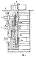
- valve body In the solenoid valve shown in FIG. 4, the valve body is provided on its outside with ring grooves which accommodate further ring seals 44. They serve to seal the valve body 1, which is arranged in a housing 45.
- the control piston 15 bears sealingly on the outer valve seat 5. It is formed in its position by a combination of the pressure of an additional spring 46 and the differential forces which are generated as a result of a smaller inner diameter of the outer valve seat 5 and a larger inner diameter of the actuating piston 20.
- the additional spring 46 is advantageously arranged between the bottom 7a of the valve body 1 and a projection of the control piston 15 coaxially with the valve lifter 16.
- the actuating piston 20 has an annular seal which is designed as a profile seal 47.
Landscapes
- Engineering & Computer Science (AREA)
- General Engineering & Computer Science (AREA)
- Mechanical Engineering (AREA)
- Physics & Mathematics (AREA)
- Electromagnetism (AREA)
- Magnetically Actuated Valves (AREA)
Priority Applications (2)
| Application Number | Priority Date | Filing Date | Title |
|---|---|---|---|
| EP89307999A EP0412212A1 (fr) | 1989-08-07 | 1989-08-07 | Clapet électromagnétique pour fluide liquide ou gazeux et sa commande |
| NO90903453A NO903453L (no) | 1989-08-07 | 1990-08-06 | Magnetventil for et flytende eller gassformig medium og fremgangsmaate til dens regulering. |
Applications Claiming Priority (1)
| Application Number | Priority Date | Filing Date | Title |
|---|---|---|---|
| EP89307999A EP0412212A1 (fr) | 1989-08-07 | 1989-08-07 | Clapet électromagnétique pour fluide liquide ou gazeux et sa commande |
Publications (1)
| Publication Number | Publication Date |
|---|---|
| EP0412212A1 true EP0412212A1 (fr) | 1991-02-13 |
Family
ID=8202753
Family Applications (1)
| Application Number | Title | Priority Date | Filing Date |
|---|---|---|---|
| EP89307999A Withdrawn EP0412212A1 (fr) | 1989-08-07 | 1989-08-07 | Clapet électromagnétique pour fluide liquide ou gazeux et sa commande |
Country Status (2)
| Country | Link |
|---|---|
| EP (1) | EP0412212A1 (fr) |
| NO (1) | NO903453L (fr) |
Cited By (3)
| Publication number | Priority date | Publication date | Assignee | Title |
|---|---|---|---|---|
| WO2005124207A1 (fr) * | 2004-06-21 | 2005-12-29 | Robertshaw Controls Company | Soupape a debit variable |
| US7806140B2 (en) | 2006-04-18 | 2010-10-05 | Robertshaw Controls Company | Power saving locking coil |
| CN116176546A (zh) * | 2023-03-10 | 2023-05-30 | 西安航空制动科技有限公司 | 一种用于飞机刹车系统的常闭型高气压电磁阀 |
Citations (3)
| Publication number | Priority date | Publication date | Assignee | Title |
|---|---|---|---|---|
| US2322911A (en) * | 1942-09-23 | 1943-06-29 | Honeywell Regulator Co | Valve mechanism |
| US2515029A (en) * | 1945-09-10 | 1950-07-11 | Midland Steel Prod Co | Valve |
| CH658304A5 (de) * | 1983-03-24 | 1986-10-31 | Sulzer Ag | Den durchfluss eines druckmediums steuerndes umschaltventil. |
-
1989
- 1989-08-07 EP EP89307999A patent/EP0412212A1/fr not_active Withdrawn
-
1990
- 1990-08-06 NO NO90903453A patent/NO903453L/no unknown
Patent Citations (3)
| Publication number | Priority date | Publication date | Assignee | Title |
|---|---|---|---|---|
| US2322911A (en) * | 1942-09-23 | 1943-06-29 | Honeywell Regulator Co | Valve mechanism |
| US2515029A (en) * | 1945-09-10 | 1950-07-11 | Midland Steel Prod Co | Valve |
| CH658304A5 (de) * | 1983-03-24 | 1986-10-31 | Sulzer Ag | Den durchfluss eines druckmediums steuerndes umschaltventil. |
Cited By (4)
| Publication number | Priority date | Publication date | Assignee | Title |
|---|---|---|---|---|
| WO2005124207A1 (fr) * | 2004-06-21 | 2005-12-29 | Robertshaw Controls Company | Soupape a debit variable |
| US7455073B2 (en) | 2004-06-21 | 2008-11-25 | Robertshaw Controls Company | Variable flow valve |
| US7806140B2 (en) | 2006-04-18 | 2010-10-05 | Robertshaw Controls Company | Power saving locking coil |
| CN116176546A (zh) * | 2023-03-10 | 2023-05-30 | 西安航空制动科技有限公司 | 一种用于飞机刹车系统的常闭型高气压电磁阀 |
Also Published As
| Publication number | Publication date |
|---|---|
| NO903453L (no) | 1991-02-08 |
| NO903453D0 (no) | 1990-08-06 |
Similar Documents
| Publication | Publication Date | Title |
|---|---|---|
| DE3903483C2 (fr) | ||
| DE3309904C2 (fr) | ||
| DE4244581A1 (de) | Elektromagnetisch gesteuerte Betätigungsvorrichtung | |
| DE3808625A1 (de) | Selbstregelndes ventil | |
| DE2737675B2 (de) | Elektromagnetisch betätigbares, mit Druckfluid umsteuerbares Wegeventil für einen Servomotor | |
| DE2528873B2 (de) | Sitzventil für die Druckmittelversorgung einer Arbeitseinheit | |
| DE3523917A1 (de) | Von einem steuerorgan betaetigtes steuerungsventil | |
| EP0681128A1 (fr) | Electrovanne | |
| EP1811216B1 (fr) | Agencement d'actionnement destiné à l'actionnement d'un agencement d'aération | |
| DE4310960A1 (de) | Verbessertes Drei-Wege- und Drei-Positions-Magnetventil | |
| DE3329734C2 (fr) | ||
| DE3780642T2 (de) | Elektromagnetisches ventil. | |
| DE2544347A1 (de) | Ventilanordnung mit zwei stufen | |
| EP1620667B1 (fr) | Dispositif electro-aimant de levage | |
| EP0412212A1 (fr) | Clapet électromagnétique pour fluide liquide ou gazeux et sa commande | |
| DE3306317A1 (de) | Mengenventil | |
| DE10107164C1 (de) | Proportional-Wegemagnetventil | |
| DE2321021A1 (de) | Mehrwege-magnetventil | |
| EP0182053B1 (fr) | Vanne de régulation de pression électromagnétiquement commandée | |
| DE2361591A1 (de) | Schieberventil zur steuerung des arbeitsdrucks eines arbeitsmediums | |
| EP1870621B1 (fr) | Robinet de commande d'un liquide | |
| DE4020164A1 (de) | Elektromagnetisch betaetigtes ventil | |
| DE19502671A1 (de) | Elektromagnetantrieb, insbesondere für Elektromagnetventile als Stellglieder für Fluide | |
| DE10030059A1 (de) | Steuereinrichtung | |
| DE3431853A1 (de) | Elektromagnetisch betaetigbares hydraulikstellglied |
Legal Events
| Date | Code | Title | Description |
|---|---|---|---|
| PUAI | Public reference made under article 153(3) epc to a published international application that has entered the european phase |
Free format text: ORIGINAL CODE: 0009012 |
|
| AK | Designated contracting states |
Kind code of ref document: A1 Designated state(s): DE GB |
|
| STAA | Information on the status of an ep patent application or granted ep patent |
Free format text: STATUS: THE APPLICATION IS DEEMED TO BE WITHDRAWN |
|
| 18D | Application deemed to be withdrawn |
Effective date: 19910814 |