EP0412283A1 - Spritzenzylinder für medizinische Zwecke - Google Patents
Spritzenzylinder für medizinische Zwecke Download PDFInfo
- Publication number
- EP0412283A1 EP0412283A1 EP90112425A EP90112425A EP0412283A1 EP 0412283 A1 EP0412283 A1 EP 0412283A1 EP 90112425 A EP90112425 A EP 90112425A EP 90112425 A EP90112425 A EP 90112425A EP 0412283 A1 EP0412283 A1 EP 0412283A1
- Authority
- EP
- European Patent Office
- Prior art keywords
- syringe
- syringe barrel
- barrel according
- cannula
- closure part
- Prior art date
- Legal status (The legal status is an assumption and is not a legal conclusion. Google has not performed a legal analysis and makes no representation as to the accuracy of the status listed.)
- Granted
Links
- 238000005192 partition Methods 0.000 claims description 12
- 239000011324 bead Substances 0.000 claims description 3
- 238000004108 freeze drying Methods 0.000 description 6
- 239000000126 substance Substances 0.000 description 6
- 238000002347 injection Methods 0.000 description 5
- 239000007924 injection Substances 0.000 description 5
- 238000003780 insertion Methods 0.000 description 2
- 230000037431 insertion Effects 0.000 description 2
- 239000002904 solvent Substances 0.000 description 2
- 238000004140 cleaning Methods 0.000 description 1
- 239000011521 glass Substances 0.000 description 1
- 238000004519 manufacturing process Methods 0.000 description 1
- 230000001954 sterilising effect Effects 0.000 description 1
- 238000004659 sterilization and disinfection Methods 0.000 description 1
Images


Classifications
-
- A—HUMAN NECESSITIES
- A61—MEDICAL OR VETERINARY SCIENCE; HYGIENE
- A61M—DEVICES FOR INTRODUCING MEDIA INTO, OR ONTO, THE BODY; DEVICES FOR TRANSDUCING BODY MEDIA OR FOR TAKING MEDIA FROM THE BODY; DEVICES FOR PRODUCING OR ENDING SLEEP OR STUPOR
- A61M5/00—Devices for bringing media into the body in a subcutaneous, intra-vascular or intramuscular way; Accessories therefor, e.g. filling or cleaning devices, arm-rests
- A61M5/178—Syringes
- A61M5/28—Syringe ampoules or carpules, i.e. ampoules or carpules provided with a needle
-
- A—HUMAN NECESSITIES
- A61—MEDICAL OR VETERINARY SCIENCE; HYGIENE
- A61M—DEVICES FOR INTRODUCING MEDIA INTO, OR ONTO, THE BODY; DEVICES FOR TRANSDUCING BODY MEDIA OR FOR TAKING MEDIA FROM THE BODY; DEVICES FOR PRODUCING OR ENDING SLEEP OR STUPOR
- A61M5/00—Devices for bringing media into the body in a subcutaneous, intra-vascular or intramuscular way; Accessories therefor, e.g. filling or cleaning devices, arm-rests
- A61M5/178—Syringes
- A61M5/28—Syringe ampoules or carpules, i.e. ampoules or carpules provided with a needle
- A61M5/284—Syringe ampoules or carpules, i.e. ampoules or carpules provided with a needle comprising means for injection of two or more media, e.g. by mixing
-
- A—HUMAN NECESSITIES
- A61—MEDICAL OR VETERINARY SCIENCE; HYGIENE
- A61M—DEVICES FOR INTRODUCING MEDIA INTO, OR ONTO, THE BODY; DEVICES FOR TRANSDUCING BODY MEDIA OR FOR TAKING MEDIA FROM THE BODY; DEVICES FOR PRODUCING OR ENDING SLEEP OR STUPOR
- A61M5/00—Devices for bringing media into the body in a subcutaneous, intra-vascular or intramuscular way; Accessories therefor, e.g. filling or cleaning devices, arm-rests
- A61M5/178—Syringes
- A61M5/31—Details
- A61M5/3129—Syringe barrels
- A61M5/3137—Specially designed finger grip means, e.g. for easy manipulation of the syringe rod
- A61M2005/3139—Finger grips not integrally formed with the syringe barrel, e.g. using adapter with finger grips
-
- A—HUMAN NECESSITIES
- A61—MEDICAL OR VETERINARY SCIENCE; HYGIENE
- A61M—DEVICES FOR INTRODUCING MEDIA INTO, OR ONTO, THE BODY; DEVICES FOR TRANSDUCING BODY MEDIA OR FOR TAKING MEDIA FROM THE BODY; DEVICES FOR PRODUCING OR ENDING SLEEP OR STUPOR
- A61M5/00—Devices for bringing media into the body in a subcutaneous, intra-vascular or intramuscular way; Accessories therefor, e.g. filling or cleaning devices, arm-rests
- A61M5/178—Syringes
- A61M5/28—Syringe ampoules or carpules, i.e. ampoules or carpules provided with a needle
- A61M5/285—Syringe ampoules or carpules, i.e. ampoules or carpules provided with a needle with sealing means to be broken or opened
- A61M5/288—Syringe ampoules or carpules, i.e. ampoules or carpules provided with a needle with sealing means to be broken or opened by piercing without internal pressure increase
-
- A—HUMAN NECESSITIES
- A61—MEDICAL OR VETERINARY SCIENCE; HYGIENE
- A61M—DEVICES FOR INTRODUCING MEDIA INTO, OR ONTO, THE BODY; DEVICES FOR TRANSDUCING BODY MEDIA OR FOR TAKING MEDIA FROM THE BODY; DEVICES FOR PRODUCING OR ENDING SLEEP OR STUPOR
- A61M5/00—Devices for bringing media into the body in a subcutaneous, intra-vascular or intramuscular way; Accessories therefor, e.g. filling or cleaning devices, arm-rests
- A61M5/178—Syringes
- A61M5/31—Details
- A61M5/3145—Filters incorporated in syringes
-
- A—HUMAN NECESSITIES
- A61—MEDICAL OR VETERINARY SCIENCE; HYGIENE
- A61M—DEVICES FOR INTRODUCING MEDIA INTO, OR ONTO, THE BODY; DEVICES FOR TRANSDUCING BODY MEDIA OR FOR TAKING MEDIA FROM THE BODY; DEVICES FOR PRODUCING OR ENDING SLEEP OR STUPOR
- A61M5/00—Devices for bringing media into the body in a subcutaneous, intra-vascular or intramuscular way; Accessories therefor, e.g. filling or cleaning devices, arm-rests
- A61M5/178—Syringes
- A61M5/31—Details
- A61M5/32—Needles; Details of needles pertaining to their connection with syringe or hub; Accessories for bringing the needle into, or holding the needle on, the body; Devices for protection of needles
- A61M5/34—Constructions for connecting the needle, e.g. to syringe nozzle or needle hub
Definitions
- the invention relates to a syringe barrel for medical purposes, with a displaceable syringe plunger and with a closure part on the cannula side.
- Such syringe barrels are preferably put on the market with injection substances and are filled. Compared to filling the injection substance into ampoules or vials, there is the advantage that there is no need to transfer the substance into the injection system before application. Rather, this can Syringe cylinders are either added directly to an injection syringe by attaching the additional parts that are still required, or they can be inserted into a so-called "pen" syringe, which - especially for diabetics - has the shape of a ballpoint pen and is equipped with a small metering pump.
- the invention has for its object to provide a syringe barrel of the type mentioned in such a way that it can be produced at minimal cost, easily and quickly filled in large series, but can nevertheless be used directly as a full syringe barrel in the application of injection substances.
- the syringe barrel is designed as a cylindrical tube which is provided at its cannula-side end on its inner circumferential surface with an annular collar which forms a snap fit for the closure part, the closure part being designed as a piercing plug which is provided on its end face opposite the syringe plunger with a sack-like recess, between the bottom and the cannula-side end face of which a pierceable partition is formed.
- the progress achieved by the invention consists first of all in that the syringe barrel has a particularly simple shape and can therefore be easily produced by cutting a glass tube, for example.
- the syringe barrel can first be provided with the closure part after cleaning and sterilization and after filling with the syringe plunger.
- the closure part designed as a piercing plug has the advantage that there is no need to open the syringe barrel before application, since with the insertion of a suitably designed needle attachment piece or the insertion of the syringe barrel into a "pen" syringe, the end facing away from the cannula tip automatically pierces the partition.
- the locking seat of the closure part ensures that it is not pressed out of its intended position when the partition is pierced. The same applies to the subsequent application, in which the syringe plunger is displaced towards the closure part.
- the sack-like recess is formed by a cylindrical bore with a flat bottom surface perpendicular to the longitudinal axis.
- the annular collar can be expediently formed by a radially inwardly projecting bead which engages in an annular groove in the piercing plug.
- the two end faces of the syringe barrel can expediently each be provided with an annular flange which is approximately circular in cross section. Then recommend it further, that the piercing plug rests with the edge of its cannula-side end face against the ring flange, whereby an overall firmer hold of the piercing plug is achieved.
- a circumferential locking groove can be provided on its outer circumferential surface for connecting an attached needle hub, the hollow cylindrical needle hub being provided with a ring bar engaging in the locking groove. It is also expedient here if a finger rest can be snapped onto the end facing away from the closure part.
- the piercing stopper can be provided with at least one bore which extends radially outward from the sack-like recess to the lateral surface. Then there is the possibility, when the closure part is initially only partially inserted into the syringe barrel, to suck the solvent out of the interior of the syringe barrel via the recess and the bore and then to move the closure portion into its intended position, as a result of which the bore or the bores through the inner surface of the syringe barrel.
- the piercing stopper can be provided on the circumference in the edge region of its end face facing away from the partition wall with a wedge-shaped groove into which the ring flange arranged at the end on the syringe barrel engages.
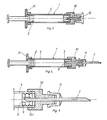
- the syringe cylinder 1 shown in the drawing is intended for medical purposes and has a displaceable syringe plunger 2 and a closure part 3 on the cannula side.
- the syringe cylinder 1 is designed as a cylindrical tube 4, which is provided at its cannula-side end 4.1 on its inner circumferential surface with an annular collar 5, which forms a snap fit for the closure part 3.
- the closure part 3 is designed as a piercing plug which is provided with a sack-like recess 6 on its end face opposite the syringe plunger 1.
- a pierceable partition 3.2 is thereby formed between the bottom 6.1 of this recess 6 and the cannula-side end face 3.1.
- the sack-like recess 6 is formed by a cylindrical bore with a flat bottom surface 6.1 perpendicular to the longitudinal axis.
- the annular collar 5 is formed by a radially inwardly projecting bead which engages in one of the annular grooves of the piercing plug. This ensures that the piercing plug assumes its intended position in the syringe barrel 1, so that when a cannula 7 is placed, for example, the partition 3.2 can also be pierced safely and that the piercing plug is also held in this position until application.
- the syringe barrel 1 is provided on its two end faces 4.1, 4.2 each with an approximately circular cross-section in the cross-section of an annular flange 8, the piercing plug being connected to the edge of it end face 3.1 on the cannula lies against this ring flange 8. In this way, the piercing plug receives an even better hold in its intended position.
- the hollow cylindrical needle attachment piece 10 On the outer circumferential surface of the syringe barrel 1 there is a locking groove 9 extending in the circumferential direction for the connection of a needle attachment piece 10 placed on the end face, the hollow cylindrical needle attachment piece 10, as can be seen in particular from FIG is.
- On the needle hub 10 is provided with a cap 11 cannula 7, one end of which extends completely through a bore in the needle hub 10 and is designed such that it pierces the partition 3.2 of the closure part 3 when it is attached.
- the syringe barrel 1 is already assembled with a needle hub 10 on which a tip cap 12 is placed, the locking pin extends through the needle hub 10 and the already opened partition 3.2 .
- a finger rest 13 can be snapped onto the end of the syringe barrel 1 facing away from the closure part 3, for which a known Luer impact cap can be used.
- the piercing stopper For the lyophilization directly in the syringe cylinder 1, the piercing stopper, as shown in FIGS. 6 to 8, is provided with two bores 14 which extend radially outward from the sack-like recess 6 to the lateral surface.
- the piercing plug in the edge region of its end face facing away from the partition 3.2 is provided on the circumference with a wedge-shaped groove 15 which is provided for receiving the ring flange 8 arranged on the end face of the syringe cylinder 1.
- the closure part 3 is held in the position shown in FIG. 7 during the lyophilization until all the solvent has been removed from the interior of the syringe barrel 1 through the bores 14.
- the piercing plug is then pressed into its intended position in the syringe barrel 1, as a result of which the bores 14 automatically close over the inner circumferential surface of the syringe barrel.
- a filter disk 16 is arranged in the sack-like recess 6, which is aligned perpendicular to the longitudinal axis and in one Ring groove is held. Insofar as the piercing plug is set up for lyophilization, this filter disk 16 is arranged between the bores 14 and the partition 3.2.
Landscapes
- Health & Medical Sciences (AREA)
- Vascular Medicine (AREA)
- Engineering & Computer Science (AREA)
- Anesthesiology (AREA)
- Biomedical Technology (AREA)
- Heart & Thoracic Surgery (AREA)
- Hematology (AREA)
- Life Sciences & Earth Sciences (AREA)
- Animal Behavior & Ethology (AREA)
- General Health & Medical Sciences (AREA)
- Public Health (AREA)
- Veterinary Medicine (AREA)
- Infusion, Injection, And Reservoir Apparatuses (AREA)
- Medicinal Preparation (AREA)
Abstract
Description
- Die Erfindung betrifft einen Spritzenzylinder für medizinische Zwecke, mit einem verschiebbaren Spritzenkolben sowie mit einem kanülenseitigen Verschlußteil.
- Solche Spritzenzylinder kommen vorzugsweise mit Injektionssubstanzen fertig abgefüllt in den Verkehr. Gegenüber einer Abfüllung der Injektionssubstanz in Ampullen oder Vials ergibt sich hierbei der Vorteil, daß eine Überführung der Substanz vor der Applikation in das Injektionssystem entfällt. Vielmehr kann dieser Spritzenzylinder entweder durch Anbringen der noch erforderlichen Zusatzteile unmittelbar zu einer Injektionsspritze ergänzt oder aber in eine sog. "Pen"-Spritze eingesetzt werden, die - insbes. für Diabetiker entwickelt - die Form eines Kugelschreibers besitzt und mit einer kleinen Dosierpumpe ausgestattet ist.
- Da es sich bei diesen Spritzenzylindern, wie bei den Ampullen auch, um Wegwerf-Produkte handelt, die im übrigen in hoher Stückzahl benötigt werden, müssen diese einfach und kostengünstig herstellbar sein.
- Der Erfindung liegt die Aufgabe zugrunde, ein Spritzenzylinder der eingangs genannten Art so auszubilden, daß er mit minimalen Kosten herstellbar, dabei in Großserien einfach und schell zu befüllen ist, dennoch aber als vollwertiger Spritzenzylinder unmittelbar bei der Applikation von Injektionssubstanzen einsetzbar ist.
- Diese Aufgabe wird nach der Erfindung dadurch gelöst, daß der Spritzenzylinder als zylindrisches Rohr ausgebildet ist, das an seinem kanülenseitigen Ende an seiner Innenmantelfläche mit einem ringförmigen Bund versehen ist, der einen Rastsitz für das Verschlußteil bildet, wobei das Verschlußteil als Durchstechstopfen ausgebildet ist, der an seiner dem Spritzenkolben gegenüber stehenden Stirnfläche mit einer sackartigen Ausnehmung versehen ist, zwischen deren Boden und der kanülenseitigen Stirnfläche eine durchstechbare Trennwand gebildet ist.
- Der durch die Erfindung erreichte Fortschritt besteht zunächst darin, daß der Spritzenzylinder eine besonders einfache Gestalt aufweist und somit ohne weiteres durch Ablängen von beispielsweise einem Glasrohr hergestellt werden kann. Nach einer Nachbearbeitung der stirnseitigen Abtrennflächen zur Beseitigung scharfer Schnittkanten und Anbringung des ringförmigen Bundes kann der Spritzenzylinder nach Reinigung und Sterilisation zunächst mit dem Verschlußteil und nach Befüllung mit dem Spritzenkolben versehen werden. Das als Durchstechstopfen ausgebildete Verschlußteil besitzt den Vorteil, daß ein Öffnen des Spritzenzylinders vor der Applikation entfällt, da mit dem Ansetzen eines geeignet ausgebildeten Nadelansatzstückes oder dem Einsetzen des Spritzenzylinders in eine "Pen"-Spritze das der Kanülenspitze abgewandte Ende selbsttätig die Trennwand durchsticht. Dabei sorgt der Rastsitz des Verschlußteils dafür, daß dieses beim Durchstechen der Trennwand nicht aus seiner vorgesehenen Lage gedrückt wird. Gleiches gilt bei der anschließenden Applikation, bei welcher der Spritzenkolben zum Verschlußteil hin verschoben wird.
- In bevorzugter Ausführungsform der Erfindung ist die sackartige Ausnehmung von einer zylindrischen Bohrung mit einer ebenen, zur Längsachse senkrechten Bodenfläche gebildet.
- Der ringförmige Bund kann zweckmäßigerweise von einem radial einwärts vorstehenden Wulst gebildet sein, der in eine Ringnut des Durchstechstopfens greift. Die beiden Stirnseiten des Spritzenzylinders können zweckmäßigerweise jeweils mit einem im Querschnitt näherungsweise kreisförmigen Ringflansch versehen sein. Dann empfiehlt es sich weiter, daß der Durchstechstopfen mit dem Rand seiner kanülenseitigen Stirnfläche dem Ringflansch anliegt, wodurch ein insgesamt festerer Halt des Durchstechstopfens erreicht wird.
- Für die Verwendung des Spritzenzylinders als konventionelle Spritze kann an seiner Außenmantelfläche eine in Umfangsrichtung verlaufende Rastnut zum Anschluß eines stirnseitig aufgesetzten Nadelansatzstückes vorgesehen sein, wobei das hohlzylindrisch ausgebildete Nadelansatzstück mit einer in die Rastnut greifenden Ringleiste versehen ist. Weiter ist es hierbei zweckmäßig, wenn an dem dem Verschlußteil abgewandten Ende eine Fingerauflage aufrastbar ist.
- Um in dem Spritzenzylinder auch unmittelbar Substanzen lyophilisieren zu können, kann der Durchstechstopfen mit zumindest einer, von der sackartigen Ausnehmung radial nach außen zur Mantelfläche sich erstreckenden Bohrung versehen sein. Dann besteht die Möglichkeit, bei zunächst nur teilweise in den Spritzenzylinder eingesetztem Verschlußteil über die Ausnehmung und die Bohrung das Lösungsmittel aus dem Inneren des Spritzenzylinders abzusaugen und anschließend das Verschlußteil in seine vorgesehene Position zu verschieben, wodurch dann die Bohrung bzw. die Bohrungen durch die Innenfläche des Spritzenzylinders verschlossen werden. Um den Halt des Verschlußteils während der Lyophilisierung zu verbessern, kann der Durchstechstopfen im Randbereich seiner der Trennwand abgewandten Stirnseite umfangsseitig mit einer keilförmigen Nut versehen sein, in die der am Spritzenzylinder endseitig angeordnete Ringflansch greift.
- Schließlich besteht noch die Möglichkeit, in der sackartigen Ausnehmung eine Filterscheibe anzuordnen, die senkrecht zur Längsachse ausgerichtet und in einer Ringnut gehalten ist.
- Im folgenden wird die Erfindung an in der Zeichnung dargestellten Ausführungsbeispielen naher erläutert; es zeigen:
- Fig. 1 den Gegenstand nach der Erfindung im Längsschnitt,
- Fig. 2 den Gegenstand nach Fig. 1 in einer modifizierten Ausführung mit einer Doppelkammer,
- Fig. 3 den Gegenstand nach Fig. 1, jedoch als Spritze konfektioniert,
- Fig. 4 eine der Fig. 3 entsprechende Darstellung, jedoch mit einem Nadelansatzstück,
- Fig. 5 eine Detaildarstellung des Gegenstands nach Fig. 4,
- Fig. 6 eine weitere Ausführungsform der Erfindung zur direkten Lyophilisierung,
- Fig. 7 die Anordnung des Verschlußteils während der Lyophilisierung,
- Fig. 8 eine Detaildarstellung des Gegenstands nach Fig. 6, jedoch mit aufgesetztem Nadelansatzstück.
- Der in der Zeichnung dargestellte Spritzenzylinder 1 ist für medizinische Zwecke vorgesehen und weist einen verschiebbaren Spritzenkolben 2 sowie ein kanülenseitiges Verschlußteil 3 auf.
- Der Spritzenzylinder 1 ist als zylindrisches Rohr 4 ausgebildet, das an seinem kanülenseitigen Ende 4.1 an seiner Innenmantelfläche mit einem ringförmigen Bund 5 versehen ist, der einen Rastsitz für das Verschlußteil 3 bildet.
- Das Verschlußteil 3 ist als Durchstechstopfen ausgebildet, der an seiner dem Spritzenkolben 1 gegenüber stehenden Stirnfläche mit einer sackartigen Ausnehmung 6 versehen ist. Zwischen dem Boden 6.1 dieser Ausnehmung 6 und der kanülenseitigen Stirnfläche 3.1 ist hierdurch eine durchstechbare Trennwand 3.2 gebildet. Dazu ist die sackartige Ausnehmung 6 von einer zylindrischen Bohrung mit einer ebenen, zur Längsachse senkrechten Bodenfläche 6.1 gebildet.
- Der ringförmige Bund 5 ist von einem radial einwärts vorstehenden Wulst gebildet, der in eine der Ringnuten des Durchstechstopfens greift. Hierdurch wird sichergestellt, daß der Durchstechstopfen seine vorgesehene Lage im Spritzenzylinder 1 einnimmt, so daß beim Aufsetzen beispielsweise einer Kanüle 7 die Trennwand 3.2 auch sicher durchstochen werden kann und daß der Durchstechstopfen darüber hinaus in dieser Lage bis zur Applikation gehalten wird. Der Spritzenzylinder 1 ist an seinen beiden Stirnseiten 4.1, 4.2 jeweils mit einem im Querschnitt näherungsweise kreisförmigen Ringflansch 8 versehen, wobei der Durchstechstopfen mit dem Rand seiner kanülenseitigen Stirnfläche 3.1 diesem Ringflansch 8 anliegt. Auf diese Weise erhält der Durchstechstopfen in seiner vorgesehenen Lage noch besseren Halt.
- An der Außenmantelfläche es Spritzenzylinders 1 ist eine in Umfangsrichtung verlaufende Rastnut 9 zum Anschluß eines stirnseitig aufgesetzten Nadelansatzstücks 10 vorgesehen, wobei das hohlzylindrisch ausgebildete Nadelansatzstück 10, wie sich dies insbes. aus Fig. 5 ergibt, mit einer in die Rastnut 9 greifenden Ringleiste 10.1 versehen ist. Auf das Nadelansatzstück 10 ist die mit einer Kappe 11 versehene Kanüle 7 aufgesetzt, deren eines Ende sich vollständig durch eine Bohrung im Nadelansatzstück 10 hindurch erstreckt und so ausgebildet ist, daß es die Trennwand 3.2 des Verschlußteils 3 beim Aufsetzen durchsticht. Dabei besteht jedoch auch die in Fig. 3 dargestellte Möglichkeit, daß der Spritzenzylinder 1 bereits mit einem Nadelansatzstück 10 fertig konfektioniert ist, auf den ein Tip-Cap 12 aufgesetzt ist, dessen Verschlußstift sich durch das Nadelansatzstück 10 sowie die schon geöffnete Trennwand 3.2 hindurch erstreckt.
- Wie sich aus den Fig. 3 und 4 ergibt, ist auf dem dem Verschlußteil 3 abgewandten Ende des Spritzenzylinders 1 eine Fingerauflage 13 aufrastbar, wofür eine an sich bekannte Luer Aufprellkappe Verwendung finden kann.
- Für die Lyophilisierung unmittelbar im Spritzenzylinder 1 ist der Durchstechstopfen, wie dies in den Fig. 6 bis 8 dargestellt ist, mit zwei von der sackartigen Ausnehmung 6 radial nach außen zur Mantelfläche sich erstreckenden Bohrungen 14 versehen. Wie sich im einzelnen aus der Fig. 7 ergibt, ist der Durchstechstopfen im Randbereich seiner der Trennwand 3.2 abgewandten Stirnseite umfangsseitig mit einer keilförmigen Nut 15 versehen, die zur Aufnahme des stirnseitig am Spritzenzylinder 1 angeordneten Ringflansches 8 vorgesehen ist. Auf diese Weise wird das Verschlußteil 3 während der Lyophilisierung in der in Fig. 7 dargestellten Stellung gehalten, bis das gesamte Lösungsmittel durch die Bohrungen 14 aus dem Inneren des Spritzenzylinders 1 entfernt ist. Anschließend wird der Durchstechstopfen in seine vorgesehene Stellung in den Spritzenzylinder 1 eingedrückt, wodurch sich die Bohrungen 14 über die Innenmantelfläche des Spritzenzylinders selbsttätig schließen.
- Um bei der Applikation der zu injizierenden Substanz zu verhindern, daß auch nicht oder sich nur schwer lösende Bestandteile oder Rückstände aus dem Spritzenzylinder 1 zur Kanüle 7 gelangen, ist in der sackartigen Ausnehmung 6 eine Filterscheibe 16 angeordnet, die senkrecht zur Längsachse ausgerichtet und in einer Ringnut gehalten ist. Diese Filterscheibe 16 ist, soweit der Durchstechstopfen für die Lyophilisierung eingerichtet ist, zwischen den Bohrungen 14 und der Trennwand 3.2 angeordnet.
Claims (10)
Applications Claiming Priority (2)
| Application Number | Priority Date | Filing Date | Title |
|---|---|---|---|
| DE3924830 | 1989-07-27 | ||
| DE3924830A DE3924830A1 (de) | 1989-07-27 | 1989-07-27 | Spritzenzylinder fuer medizinische zwecke |
Publications (2)
| Publication Number | Publication Date |
|---|---|
| EP0412283A1 true EP0412283A1 (de) | 1991-02-13 |
| EP0412283B1 EP0412283B1 (de) | 1993-12-01 |
Family
ID=6385941
Family Applications (1)
| Application Number | Title | Priority Date | Filing Date |
|---|---|---|---|
| EP90112425A Expired - Lifetime EP0412283B1 (de) | 1989-07-27 | 1990-06-29 | Spritzenzylinder für medizinische Zwecke |
Country Status (7)
| Country | Link |
|---|---|
| US (1) | US5139490A (de) |
| EP (1) | EP0412283B1 (de) |
| JP (1) | JPH0382476A (de) |
| AT (1) | ATE97821T1 (de) |
| DE (2) | DE3924830A1 (de) |
| DK (1) | DK0412283T3 (de) |
| ES (1) | ES2046599T3 (de) |
Cited By (2)
| Publication number | Priority date | Publication date | Assignee | Title |
|---|---|---|---|---|
| EP0830868A3 (de) * | 1996-09-23 | 1998-05-13 | Arzneimittel GmbH Apotheker Vetter & Co. Ravensburg | Vorgefüllte Spritze für medizinische Zwecke |
| US6807797B2 (en) | 1997-09-23 | 2004-10-26 | Pharmacia Ab | Prefilled ampoules and manufacture thereof |
Families Citing this family (52)
| Publication number | Priority date | Publication date | Assignee | Title |
|---|---|---|---|---|
| DE4127650C1 (de) * | 1991-08-21 | 1993-02-25 | Arzneimittel Gmbh Apotheker Vetter & Co Ravensburg, 7980 Ravensburg, De | |
| IL105396A (en) * | 1992-04-30 | 1998-02-22 | Takeda Chemical Industries Ltd | Prefilled syringe |
| RU2130323C1 (ru) * | 1992-04-30 | 1999-05-20 | Такеда Кемикал Индастриз, Лтд. | Предварительно заполненный шприц и способ его загрузки |
| US5586975A (en) * | 1994-02-18 | 1996-12-24 | Takeda Chemical Industries. Ltd. | Air and liquid tight container with a slidable gasket |
| US5549575A (en) * | 1994-09-13 | 1996-08-27 | Becton Dickinson And Company | Cartridge retainer assembly for medication delivery pen |
| DE4434644C2 (de) | 1994-09-28 | 1997-08-07 | Schott Glaswerke | Behältnis zur Lagerung und Verabreichung von Injektions-, Infusions- und Diagnostikpräparaten |
| US5836919A (en) * | 1996-05-23 | 1998-11-17 | Solopak Pharmaceuticals, Inc. | Cap assembly |
| DE19723851C1 (de) | 1997-06-06 | 1998-10-08 | Schott Glas | Griffleiste für vorgefüllte Einmalspritzen |
| DE19801861C2 (de) * | 1998-01-20 | 2001-10-18 | Schott Glas | Verfahren zum Herstellen eines hohlen, innenbeschichteten Glasformkörpers |
| DE19840532A1 (de) * | 1998-08-28 | 2000-03-09 | Schering Ag | Mit Ultraschallkonstrastmittel gefüllte Spritze mit einer mechanischen Bewegungsvorrichtung |
| JP2003527159A (ja) * | 1999-10-22 | 2003-09-16 | アンタレス・ファーマ・インコーポレーテッド | 薬剤カートリッジ及び注射装置 |
| AUPQ526100A0 (en) * | 2000-01-25 | 2000-02-17 | Ferrier International Limited | Improvements in single use syringes |
| US8100865B2 (en) * | 2000-06-15 | 2012-01-24 | Hambley Limited | Hypodermic syringe with passive aspiration feature |
| DE10140704A1 (de) * | 2001-08-18 | 2003-03-06 | Vetter & Co Apotheker | Verfahren zur Durchmischung einer schwer löslichen pharmazeutischen Substanz mit einem Lösungsmittel und Spritze zur Anwendung des Verfahrens |
| ATE409057T1 (de) | 2002-02-11 | 2008-10-15 | Antares Pharma Inc | Intradermales injektionsgerät |
| KR20040096561A (ko) | 2002-02-15 | 2004-11-16 | 앤태어스 파머, 인코퍼레이티드 | 바이패스 채널을 구비한 주사기 |
| US7998106B2 (en) | 2004-05-03 | 2011-08-16 | Thorne Jr Gale H | Safety dispensing system for hazardous substances |
| US7731678B2 (en) | 2004-10-13 | 2010-06-08 | Hyprotek, Inc. | Syringe devices and methods for mixing and administering medication |
| AT500930B1 (de) | 2004-10-25 | 2007-03-15 | Pharma Consult Ges M B H & Co | Verfahren und vorrichtung zum lyophilisieren, rekonstituieren und verabreichen eines rekonstituierten wirkstoffes |
| CN101312759B (zh) * | 2004-12-24 | 2013-04-10 | 科林专利控股有限公司 | 安全注射器 |
| WO2006079064A1 (en) | 2005-01-24 | 2006-07-27 | Antares Pharma, Inc. | Prefilled needle assisted jet injector |
| DK2058020T3 (da) | 2005-02-01 | 2013-01-07 | Intelliject Inc | Indretning til indgivelse af lægemiddel |
| CA2626864C (en) | 2005-11-09 | 2015-06-02 | Hyprotek, Inc. | Syringe devices, components of syringe devices, and methods of forming components and syringe devices |
| US8251947B2 (en) | 2006-05-03 | 2012-08-28 | Antares Pharma, Inc. | Two-stage reconstituting injector |
| CN101873872A (zh) * | 2007-09-27 | 2010-10-27 | 贝克顿·迪金森公司 | 用于粉末和液体药物的药筒 |
| US8002737B2 (en) | 2007-10-04 | 2011-08-23 | Hyprotek, Inc. | Mixing/administration syringe devices, protective packaging and methods of protecting syringe handlers |
| US9522097B2 (en) | 2007-10-04 | 2016-12-20 | Hyprotek, Inc. | Mixing/administration syringe devices, protective packaging and methods of protecting syringe handlers |
| US9504816B2 (en) | 2008-03-17 | 2016-11-29 | Syringetech Llc | Multi-mode syringe |
| EP3581224A1 (de) | 2008-08-05 | 2019-12-18 | Antares Pharma, Inc. | Injektor mit mehrfachdosierung |
| AU2010226442A1 (en) | 2009-03-20 | 2011-10-13 | Antares Pharma, Inc. | Hazardous agent injection system |
| EP2506892B1 (de) * | 2009-12-04 | 2020-05-13 | Becton, Dickinson and Company | Kartusche zur abfüllung und ausgabe eines medikaments |
| US9173999B2 (en) | 2011-01-26 | 2015-11-03 | Kaleo, Inc. | Devices and methods for delivering medicaments from a multi-chamber container |
| US10092688B2 (en) | 2011-05-13 | 2018-10-09 | Laura Jean Robinson | Medicament kit and method of use |
| US9220660B2 (en) | 2011-07-15 | 2015-12-29 | Antares Pharma, Inc. | Liquid-transfer adapter beveled spike |
| US8496619B2 (en) | 2011-07-15 | 2013-07-30 | Antares Pharma, Inc. | Injection device with cammed ram assembly |
| WO2013017415A1 (en) * | 2011-08-02 | 2013-02-07 | Sanofi-Aventis Deutschland Gmbh | Drug delivery device and cartridge to be interconnected therewith |
| US11203000B2 (en) | 2011-10-20 | 2021-12-21 | Becton, Dickinson And Company | Mixing element for container assemblies |
| US9751056B2 (en) | 2012-01-23 | 2017-09-05 | Merit Medical Systems, Inc. | Mixing syringe |
| US8834449B2 (en) | 2012-01-23 | 2014-09-16 | Ikomed Technologies, Inc. | Mixing syringe |
| EP2833944A4 (de) | 2012-04-06 | 2016-05-25 | Antares Pharma Inc | Verabreichung von testosteron-zusammensetzungen durch nadelgestützte düseninjektion |
| US9364610B2 (en) | 2012-05-07 | 2016-06-14 | Antares Pharma, Inc. | Injection device with cammed ram assembly |
| US9522235B2 (en) | 2012-05-22 | 2016-12-20 | Kaleo, Inc. | Devices and methods for delivering medicaments from a multi-chamber container |
| EP2934420B1 (de) | 2012-12-21 | 2018-02-07 | Peter Skufca | Primärverpackung zur lagerung und/oder verabreichung medizinischer oder pharmazeutischer verbindungen |
| PT2953667T (pt) | 2013-02-11 | 2020-01-28 | Antares Pharma Inc | Dispositivo de injeção a jato auxiliado por agulha tendo força de gatilho reduzida |
| JP6030803B2 (ja) | 2013-03-11 | 2016-11-24 | アンタレス・ファーマ・インコーポレーテッド | ピニオンシステムを有する用量注射器 |
| EP3107602B1 (de) | 2014-02-18 | 2018-03-28 | Peter Skufca | Ausgabesystem zur ausgabe von medizinischen oder pharmazeutischen verbindungen |
| WO2015124172A1 (en) | 2014-02-18 | 2015-08-27 | Peter Skufca | Delivery system for delivering medical or pharmaceutical compounds |
| EP3274021B1 (de) | 2015-03-24 | 2024-02-14 | Kaleo, Inc. | Vorrichtungen und verfahren zur abgabe eines lyophilisierten medikaments |
| AU2016287571C1 (en) | 2015-06-30 | 2021-12-23 | Kaleo, Inc. | Auto-injectors for administration of a medicament within a prefilled syringe |
| EP3902584A4 (de) | 2018-12-29 | 2022-09-07 | Kaleo, Inc. | Vorrichtungen und verfahren zur abgabe von substanzen in einer vorgefüllten spritze |
| US11167087B2 (en) | 2019-08-09 | 2021-11-09 | Kaleo, Inc. | Devices and methods for delivery of substances within a prefilled syringe |
| US12268847B1 (en) | 2021-02-10 | 2025-04-08 | Kaleo, Inc. | Devices and methods for delivery of substances within a medicament container |
Citations (8)
| Publication number | Priority date | Publication date | Assignee | Title |
|---|---|---|---|---|
| US1803316A (en) * | 1927-12-16 | 1931-05-05 | Cook Lab Inc | Hypodermic syringe |
| DE577364C (de) * | 1933-05-29 | I G Farbenindustrie Akt Ges | Durch Zuschmelzen verschlossene Ampulle | |
| US2368431A (en) * | 1943-07-19 | 1945-01-30 | Arthur E Smith | Ampoule |
| DE1491688A1 (de) * | 1966-02-08 | 1969-07-17 | Disponalbe Articies Res Trade | Nadelfutteral und Spritzenkopf fuer medizinische und zahnmedizinische Zwecke |
| DE2258371A1 (de) * | 1972-11-24 | 1974-06-06 | Mpl Inc | Aus kunststoff und glas bestehende spritzenanordnung mit darin vorliegender, herausdrueckbarer elastischer stopfendichtung |
| AU491860B2 (en) * | 1974-07-18 | 1976-05-06 | Ampoules, Inc | Two-chamber mixing syringe |
| CH575765A5 (de) * | 1973-03-28 | 1976-05-31 | Hoechst Ag | |
| DE2617017A1 (de) * | 1975-11-05 | 1977-05-12 | Lezard Sa | Spritzampulle |
Family Cites Families (17)
| Publication number | Priority date | Publication date | Assignee | Title |
|---|---|---|---|---|
| US1734154A (en) * | 1927-12-16 | 1929-11-05 | Cook Lab Inc | Hypodermic syringe |
| US2102704A (en) * | 1935-06-10 | 1937-12-21 | George N Hein | Syringe cartridge |
| GB495067A (en) * | 1936-05-09 | 1938-11-07 | Ig Farbenindustrie Ag | Improvements in or relating to injection syringes |
| US2483825A (en) * | 1946-08-12 | 1949-10-04 | Samuel D Goldberg | Syringe and ampoule combination and ampoule |
| US2531893A (en) * | 1947-10-25 | 1950-11-28 | Mizzy Inc | Hypodermic syringe |
| US2526365A (en) * | 1949-03-07 | 1950-10-17 | Jorgensen Niels Bjorn | Hypodermic syringe |
| US2764981A (en) * | 1955-09-01 | 1956-10-02 | Norman D Helmer | Multiple dosage syringe |
| BE672607A (de) * | 1965-11-19 | 1966-03-16 | ||
| BE755165A (fr) * | 1969-08-23 | 1971-02-22 | Philips Nv | Bouchon elastiquement deformable pour seringue d'injection |
| US3757779A (en) * | 1971-05-24 | 1973-09-11 | Century Labor Inc | Filter syringe |
| US3811441A (en) * | 1972-02-10 | 1974-05-21 | Survival Technology | Cartridge syringe |
| NL180634C (nl) * | 1977-12-23 | 1987-04-01 | Duphar Int Res | Injectiespuit alsmede naaldhouder hiervoor. |
| FR2416848A1 (fr) * | 1978-02-08 | 1979-09-07 | Rumpler Jean Jacques | Bouchon de recipient de produits medicamenteux |
| JPS5861251U (ja) * | 1981-10-22 | 1983-04-25 | 石川 惣二 | 注射針 |
| WO1988000479A1 (fr) * | 1986-07-11 | 1988-01-28 | Arzneimittel Gmbh Apotheker Vetter & Co. Ravensbur | Seringue pour usage medical |
| DE3736343C2 (de) * | 1987-10-27 | 1996-07-18 | Wasserburger Arzneimittelwerk | Injektionsspritze |
| US5084040A (en) * | 1990-01-25 | 1992-01-28 | The West Company, Incorporated | Lyophilization device |
-
1989
- 1989-07-27 DE DE3924830A patent/DE3924830A1/de not_active Withdrawn
-
1990
- 1990-06-29 DK DK90112425.5T patent/DK0412283T3/da active
- 1990-06-29 ES ES199090112425T patent/ES2046599T3/es not_active Expired - Lifetime
- 1990-06-29 AT AT90112425T patent/ATE97821T1/de not_active IP Right Cessation
- 1990-06-29 DE DE90112425T patent/DE59003673D1/de not_active Expired - Lifetime
- 1990-06-29 EP EP90112425A patent/EP0412283B1/de not_active Expired - Lifetime
- 1990-07-24 US US07/557,387 patent/US5139490A/en not_active Expired - Lifetime
- 1990-07-27 JP JP2201041A patent/JPH0382476A/ja active Granted
Patent Citations (8)
| Publication number | Priority date | Publication date | Assignee | Title |
|---|---|---|---|---|
| DE577364C (de) * | 1933-05-29 | I G Farbenindustrie Akt Ges | Durch Zuschmelzen verschlossene Ampulle | |
| US1803316A (en) * | 1927-12-16 | 1931-05-05 | Cook Lab Inc | Hypodermic syringe |
| US2368431A (en) * | 1943-07-19 | 1945-01-30 | Arthur E Smith | Ampoule |
| DE1491688A1 (de) * | 1966-02-08 | 1969-07-17 | Disponalbe Articies Res Trade | Nadelfutteral und Spritzenkopf fuer medizinische und zahnmedizinische Zwecke |
| DE2258371A1 (de) * | 1972-11-24 | 1974-06-06 | Mpl Inc | Aus kunststoff und glas bestehende spritzenanordnung mit darin vorliegender, herausdrueckbarer elastischer stopfendichtung |
| CH575765A5 (de) * | 1973-03-28 | 1976-05-31 | Hoechst Ag | |
| AU491860B2 (en) * | 1974-07-18 | 1976-05-06 | Ampoules, Inc | Two-chamber mixing syringe |
| DE2617017A1 (de) * | 1975-11-05 | 1977-05-12 | Lezard Sa | Spritzampulle |
Cited By (2)
| Publication number | Priority date | Publication date | Assignee | Title |
|---|---|---|---|---|
| EP0830868A3 (de) * | 1996-09-23 | 1998-05-13 | Arzneimittel GmbH Apotheker Vetter & Co. Ravensburg | Vorgefüllte Spritze für medizinische Zwecke |
| US6807797B2 (en) | 1997-09-23 | 2004-10-26 | Pharmacia Ab | Prefilled ampoules and manufacture thereof |
Also Published As
| Publication number | Publication date |
|---|---|
| US5139490A (en) | 1992-08-18 |
| EP0412283B1 (de) | 1993-12-01 |
| DE3924830A1 (de) | 1991-02-07 |
| ATE97821T1 (de) | 1993-12-15 |
| JPH0382476A (ja) | 1991-04-08 |
| DK0412283T3 (da) | 1994-01-17 |
| JPH0436030B2 (de) | 1992-06-12 |
| DE59003673D1 (de) | 1994-01-13 |
| ES2046599T3 (es) | 1994-02-01 |
Similar Documents
| Publication | Publication Date | Title |
|---|---|---|
| EP0412283B1 (de) | Spritzenzylinder für medizinische Zwecke | |
| DE4127650C1 (de) | ||
| DE3686636T2 (de) | Kraftangetriebene spritze mit einem adapter fuer volumenverminderung. | |
| DE3823266C2 (de) | Spritzampulle | |
| EP0830868B1 (de) | Vorgefüllte Spritze für medizinische Zwecke | |
| DE2909002C3 (de) | Injektionsspritze für einmalige Verwendung | |
| DE2744439C2 (de) | Einweg-Injektionsspritze | |
| DE69008850T2 (de) | Spritze mit auswechselbarer und zurückziehbarer kanülenplattform. | |
| DE69930393T2 (de) | Medizinische sicherheitsspritze mit züruckziebarer nadel | |
| EP0397977B1 (de) | Spritze für medizinische Zwecke | |
| DE69726531T2 (de) | Verriegelbare Schutzhülse für vorgefüllte Spritze | |
| DE69526556T2 (de) | Spritze | |
| DE2513397C2 (de) | Hohlzylindrischer Patronenhalter für eine Injektionsspritze | |
| DE69430134T2 (de) | Hypodermische spritze mit zurückziehbarer nadelmontage | |
| DE69508629T2 (de) | Spritze und Verfahren zur Lyophilisierung und Wiederherstellung von einspritzbaren Medikamenten | |
| DE2445535A1 (de) | Injektionsspritze | |
| DE69504649T2 (de) | Injektionsspritze | |
| EP0160711A1 (de) | Injektionsspritze | |
| EP0144483A2 (de) | Spritze für medizinische Zwecke | |
| DE2315367A1 (de) | Injektionsspritze zur einmaligen verwendung | |
| WO2000040284A1 (de) | Injektionsspritze | |
| DE69417340T2 (de) | Spritze für medizinische zwecke | |
| EP0498376A1 (de) | Selbstzerstörende Einweg-Sicherheitsspritze | |
| WO2010085903A1 (de) | Verabreichungsvorrichtung mit halteelement für fluidbehälter | |
| DE19915272A1 (de) | Spritze für medizinische Zwecke |
Legal Events
| Date | Code | Title | Description |
|---|---|---|---|
| PUAI | Public reference made under article 153(3) epc to a published international application that has entered the european phase |
Free format text: ORIGINAL CODE: 0009012 |
|
| AK | Designated contracting states |
Kind code of ref document: A1 Designated state(s): AT BE CH DE DK ES FR GB GR IT LI LU NL SE |
|
| 17P | Request for examination filed |
Effective date: 19910622 |
|
| 17Q | First examination report despatched |
Effective date: 19920930 |
|
| GRAA | (expected) grant |
Free format text: ORIGINAL CODE: 0009210 |
|
| AK | Designated contracting states |
Kind code of ref document: B1 Designated state(s): AT BE CH DE DK ES FR GB GR IT LI LU NL SE |
|
| REF | Corresponds to: |
Ref document number: 97821 Country of ref document: AT Date of ref document: 19931215 Kind code of ref document: T |
|
| ITF | It: translation for a ep patent filed | ||
| REF | Corresponds to: |
Ref document number: 59003673 Country of ref document: DE Date of ref document: 19940113 |
|
| REG | Reference to a national code |
Ref country code: DK Ref legal event code: T3 |
|
| ET | Fr: translation filed | ||
| REG | Reference to a national code |
Ref country code: ES Ref legal event code: FG2A Ref document number: 2046599 Country of ref document: ES Kind code of ref document: T3 |
|
| GBT | Gb: translation of ep patent filed (gb section 77(6)(a)/1977) |
Effective date: 19940224 |
|
| REG | Reference to a national code |
Ref country code: GR Ref legal event code: FG4A Free format text: 3010844 |
|
| EPTA | Lu: last paid annual fee | ||
| PLBE | No opposition filed within time limit |
Free format text: ORIGINAL CODE: 0009261 |
|
| STAA | Information on the status of an ep patent application or granted ep patent |
Free format text: STATUS: NO OPPOSITION FILED WITHIN TIME LIMIT |
|
| 26N | No opposition filed | ||
| EAL | Se: european patent in force in sweden |
Ref document number: 90112425.5 |
|
| REG | Reference to a national code |
Ref country code: GB Ref legal event code: IF02 |
|
| REG | Reference to a national code |
Ref country code: CH Ref legal event code: PCAR Free format text: ISLER & PEDRAZZINI AG;POSTFACH 1772;8027 ZUERICH (CH) |
|
| PGFP | Annual fee paid to national office [announced via postgrant information from national office to epo] |
Ref country code: ES Payment date: 20090610 Year of fee payment: 20 Ref country code: DK Payment date: 20090608 Year of fee payment: 20 Ref country code: NL Payment date: 20090630 Year of fee payment: 20 |
|
| PGFP | Annual fee paid to national office [announced via postgrant information from national office to epo] |
Ref country code: LU Payment date: 20090525 Year of fee payment: 20 Ref country code: SE Payment date: 20090625 Year of fee payment: 20 Ref country code: AT Payment date: 20090630 Year of fee payment: 20 Ref country code: IT Payment date: 20090625 Year of fee payment: 20 Ref country code: FR Payment date: 20090506 Year of fee payment: 20 |
|
| PGFP | Annual fee paid to national office [announced via postgrant information from national office to epo] |
Ref country code: BE Payment date: 20090630 Year of fee payment: 20 |
|
| PGFP | Annual fee paid to national office [announced via postgrant information from national office to epo] |
Ref country code: DE Payment date: 20090811 Year of fee payment: 20 Ref country code: CH Payment date: 20090708 Year of fee payment: 20 Ref country code: GB Payment date: 20090506 Year of fee payment: 20 Ref country code: GR Payment date: 20090513 Year of fee payment: 20 |
|
| BE20 | Be: patent expired |
Owner name: ARZNEIMITTEL G.M.B.H. APOTHEKER *VETTER & CO. RAVE Effective date: 20100629 |
|
| REG | Reference to a national code |
Ref country code: NL Ref legal event code: V4 Effective date: 20100629 |
|
| REG | Reference to a national code |
Ref country code: CH Ref legal event code: PL |
|
| REG | Reference to a national code |
Ref country code: DK Ref legal event code: EUP |
|
| REG | Reference to a national code |
Ref country code: GB Ref legal event code: PE20 Expiry date: 20100628 |
|
| EUG | Se: european patent has lapsed | ||
| REG | Reference to a national code |
Ref country code: ES Ref legal event code: FD2A Effective date: 20100630 |
|
| PG25 | Lapsed in a contracting state [announced via postgrant information from national office to epo] |
Ref country code: NL Free format text: LAPSE BECAUSE OF EXPIRATION OF PROTECTION Effective date: 20100629 Ref country code: ES Free format text: LAPSE BECAUSE OF EXPIRATION OF PROTECTION Effective date: 20100630 |
|
| PG25 | Lapsed in a contracting state [announced via postgrant information from national office to epo] |
Ref country code: GB Free format text: LAPSE BECAUSE OF EXPIRATION OF PROTECTION Effective date: 20100628 |
|
| PG25 | Lapsed in a contracting state [announced via postgrant information from national office to epo] |
Ref country code: DE Free format text: LAPSE BECAUSE OF EXPIRATION OF PROTECTION Effective date: 20100629 |