EP0412311A1 - Gyroscope à fibre optique du type Sagnac - Google Patents
Gyroscope à fibre optique du type Sagnac Download PDFInfo
- Publication number
- EP0412311A1 EP0412311A1 EP90113351A EP90113351A EP0412311A1 EP 0412311 A1 EP0412311 A1 EP 0412311A1 EP 90113351 A EP90113351 A EP 90113351A EP 90113351 A EP90113351 A EP 90113351A EP 0412311 A1 EP0412311 A1 EP 0412311A1
- Authority
- EP
- European Patent Office
- Prior art keywords
- fiber
- coupling
- directional coupler
- gates
- coupler
- Prior art date
- Legal status (The legal status is an assumption and is not a legal conclusion. Google has not performed a legal analysis and makes no representation as to the accuracy of the status listed.)
- Granted
Links
- 239000000835 fiber Substances 0.000 title claims abstract description 38
- 230000008878 coupling Effects 0.000 claims abstract description 40
- 238000010168 coupling process Methods 0.000 claims abstract description 40
- 238000005859 coupling reaction Methods 0.000 claims abstract description 40
- 239000013307 optical fiber Substances 0.000 claims abstract description 7
- 102220619539 Protein-L-histidine N-pros-methyltransferase_K46L_mutation Human genes 0.000 claims description 2
- 102220619456 Protein-L-histidine N-pros-methyltransferase_K47L_mutation Human genes 0.000 claims description 2
- 238000010438 heat treatment Methods 0.000 claims description 2
- 230000010363 phase shift Effects 0.000 description 3
- 230000005540 biological transmission Effects 0.000 description 2
- 238000001514 detection method Methods 0.000 description 2
- 238000005259 measurement Methods 0.000 description 2
- 230000035945 sensitivity Effects 0.000 description 2
- 238000005253 cladding Methods 0.000 description 1
- 230000001419 dependent effect Effects 0.000 description 1
- 238000010586 diagram Methods 0.000 description 1
- 239000011159 matrix material Substances 0.000 description 1
- 238000002844 melting Methods 0.000 description 1
- 230000008018 melting Effects 0.000 description 1
- 238000010309 melting process Methods 0.000 description 1
- 238000012544 monitoring process Methods 0.000 description 1
Images

Classifications
-
- G—PHYSICS
- G01—MEASURING; TESTING
- G01C—MEASURING DISTANCES, LEVELS OR BEARINGS; SURVEYING; NAVIGATION; GYROSCOPIC INSTRUMENTS; PHOTOGRAMMETRY OR VIDEOGRAMMETRY
- G01C19/00—Gyroscopes; Turn-sensitive devices using vibrating masses; Turn-sensitive devices without moving masses; Measuring angular rate using gyroscopic effects
- G01C19/58—Turn-sensitive devices without moving masses
- G01C19/64—Gyrometers using the Sagnac effect, i.e. rotation-induced shifts between counter-rotating electromagnetic beams
- G01C19/72—Gyrometers using the Sagnac effect, i.e. rotation-induced shifts between counter-rotating electromagnetic beams with counter-rotating light beams in a passive ring, e.g. fibre laser gyrometers
- G01C19/725—Gyrometers using the Sagnac effect, i.e. rotation-induced shifts between counter-rotating electromagnetic beams with counter-rotating light beams in a passive ring, e.g. fibre laser gyrometers using nxn optical couplers, e.g. 3x3 couplers
Definitions
- Phase shift by pi / 2 are generated so that the cosine dependence of the interference signal becomes a sine dependence.
- a disadvantage of such a solution is the necessary additional modulator, which e.g. works piezomechanically or electro-optically.
- the invention has for its object to provide a fiber gyroscope of the type in question, which works automatically in the vicinity of the quadrature point.
- an eight-port directional coupler each with four arms leading to gates, is used on both sides of the coupling area, the power being distributed to the four output gates with a certain relative phase shift between the output signals of the coupler.
- the directional coupler is preferably produced from four monomode fibers which lie against one another in the coupling region and are melted on by uniform heating.
- the coupling area thus created is preferably drawn as a biconical taper.
- the monomode fibers can still be twisted in the coupling area before melting.
- the tapering of the four fiber cores in the coupling region produced by the biconical drawing the light guided in the fiber cores by total reflection is guided more weakly.
- Such an evanescent coupling of the amplitudes lapping into the cladding region of the optical fiber to the neighboring fiber cores results in the desired distribution of the energy between the four optical fibers.
- the characteristic of the (4 x 4) coupler which is essential for the desired mode of operation of the fiber gyroscope in or near the quadrature point, is adjacent to that Power distribution to the four outputs in a certain relative phase shift between the output signals of the (4 x 4) coupler.
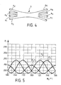
- a fiber gyro 1 has a (4 x 4) directional coupler 2, which has on both sides four gates T1 to T4 or T5 to T6, the associated arms A1 to A4 or A5 to A8 each to one Lead coupling area 3 in which they are connected to each other.
- the gates T2 With the gate T1 a light source L is connected, the gates T2, T3 and T4 are connected to receiver diodes D2, D3 and D4.
- the gates T6 and T7 on the opposite side are connected to a fiber coil 4 made of a long single-mode optical fiber 5.
- the gates T5 and T8 remain free or are connected to monitoring circuits with which, for example, the intensity of the light source is checked and taken into account in the measurement results.
- the light source L preferably emits unpolarized light in a broadband frequency range. This light is evenly distributed in the coupling area 3 to the two gates T6 and T7, with which the two ends of the fiber spool are connected, so that the split light components pass through the fiber spool 4 in opposite directions. The light enters after passing through the fiber spool 4 again through the gates T6 and T7 in the directional coupler 2 and interferes in the coupling area 3. The interference signal is passed to the receiving diodes D2, D3 and D4, from whose output signals the rate of rotation of the fiber gyro is determined becomes.
- the directional coupler 2 is e.g. Manufactured so that four monomode optical fibers are twisted together in the later coupling area 3 and carefully heated so that they melt together. During the melting process, the arrangement is drawn in such a way that the coupling area is given a biconical shape corresponding to FIG. 4, the thinnest point of which lies in the middle of the coupling area 3. The four optical fibers at both ends of the fused coupling area then form the arms A1 to A4 or A5 to A8.
- the (4 x 4) directional coupler 2 While a known (3 x 3) directional coupler should be constructed as symmetrically as possible in order to have high sensitivity for the measurement of low rotation rates, for which purpose all three coupling constants are of the same size and the coupling length is selected so that the energy distribution to each of the three arms of the directional coupler Is third, the (4 x 4) directional coupler 2 according to the invention have asymmetrical power distribution so that the received signals do not depend on a pure cosine function of the Sagnac phase.
- the indices i and j of the coupling constants correspond to the indices of the gates T k and the arms A k , so that, for example, the coupling constant K16 represent the coupling between the arms A1 and A6 in the coupling area 3.
- the directional coupler has fixed, defined phase relationships between its output amplitudes and does not merely represent a power distributor without fixed phase relationships.
Landscapes
- Physics & Mathematics (AREA)
- Engineering & Computer Science (AREA)
- Optics & Photonics (AREA)
- Electromagnetism (AREA)
- Power Engineering (AREA)
- General Physics & Mathematics (AREA)
- Radar, Positioning & Navigation (AREA)
- Remote Sensing (AREA)
- Gyroscopes (AREA)
Applications Claiming Priority (2)
| Application Number | Priority Date | Filing Date | Title |
|---|---|---|---|
| DE3926313A DE3926313A1 (de) | 1989-08-09 | 1989-08-09 | Faserkreisel vom sagnac-typ |
| DE3926313 | 1989-08-09 |
Publications (2)
| Publication Number | Publication Date |
|---|---|
| EP0412311A1 true EP0412311A1 (fr) | 1991-02-13 |
| EP0412311B1 EP0412311B1 (fr) | 1992-05-13 |
Family
ID=6386800
Family Applications (1)
| Application Number | Title | Priority Date | Filing Date |
|---|---|---|---|
| EP90113351A Expired - Lifetime EP0412311B1 (fr) | 1989-08-09 | 1990-07-12 | Gyroscope à fibre optique du type Sagnac |
Country Status (3)
| Country | Link |
|---|---|
| US (1) | US5118190A (fr) |
| EP (1) | EP0412311B1 (fr) |
| DE (2) | DE3926313A1 (fr) |
Families Citing this family (5)
| Publication number | Priority date | Publication date | Assignee | Title |
|---|---|---|---|---|
| DE4301479A1 (de) * | 1993-01-21 | 1994-07-28 | Deutsche Aerospace | Verfahren und Vorrichtung zum Korrigieren der Meßsignale eines Faserkreisels |
| US5854678A (en) * | 1996-06-28 | 1998-12-29 | Honeywell Inc. | Three-axis fiber optic gyroscope having a single source and multi-coupler configuration |
| US10009115B2 (en) * | 2011-05-02 | 2018-06-26 | Massachusetts Institute Of Technology | Optical receiver configurable to accommodate a variety of modulation formats |
| CA3030308C (fr) | 2016-07-29 | 2022-04-05 | The Board Of Trustees Of Western Michigan University | Capteur gyroscopique a base de nanoparticules magnetiques |
| CN116026329B (zh) * | 2023-03-31 | 2023-05-30 | 中国船舶集团有限公司第七〇七研究所 | 高可靠性惯性组件及惯导系统 |
Citations (2)
| Publication number | Priority date | Publication date | Assignee | Title |
|---|---|---|---|---|
| US4440498A (en) * | 1981-11-13 | 1984-04-03 | The United States Of America As Represented By The Secretary Of The Navy | Optical fiber gyroscope with (3×3) directional coupler |
| US4479715A (en) * | 1982-03-09 | 1984-10-30 | Sheem Sang K | Optical rotation-sensing interferometer with (3×3)-(2×2) directional coupler |
Family Cites Families (5)
| Publication number | Priority date | Publication date | Assignee | Title |
|---|---|---|---|---|
| US4445780A (en) * | 1982-03-01 | 1984-05-01 | The United States Of America As Represented By The Secretary Of The Navy | Fiber optic rotation-sensing gyroscope with (3×2) coupler |
| JPS6021706U (ja) * | 1983-07-19 | 1985-02-14 | アルプス電気株式会社 | スタ−カプラ |
| US4573797A (en) * | 1984-02-24 | 1986-03-04 | The United States Of America As Represented By The Secretary Of The Navy | Analog fiber gyro with extended linear range |
| US4674881A (en) * | 1984-04-25 | 1987-06-23 | Northrop Corporation | Open loop thin film laser gyro |
| EP0219096A3 (fr) * | 1985-10-16 | 1989-08-16 | Hitachi, Ltd. | Coupleur étoile à fibre optique et son procédé de fabrication |
-
1989
- 1989-08-09 DE DE3926313A patent/DE3926313A1/de active Granted
-
1990
- 1990-07-12 DE DE9090113351T patent/DE59000125D1/de not_active Expired - Fee Related
- 1990-07-12 EP EP90113351A patent/EP0412311B1/fr not_active Expired - Lifetime
- 1990-08-09 US US07/564,754 patent/US5118190A/en not_active Expired - Fee Related
Patent Citations (2)
| Publication number | Priority date | Publication date | Assignee | Title |
|---|---|---|---|---|
| US4440498A (en) * | 1981-11-13 | 1984-04-03 | The United States Of America As Represented By The Secretary Of The Navy | Optical fiber gyroscope with (3×3) directional coupler |
| US4479715A (en) * | 1982-03-09 | 1984-10-30 | Sheem Sang K | Optical rotation-sensing interferometer with (3×3)-(2×2) directional coupler |
Also Published As
| Publication number | Publication date |
|---|---|
| EP0412311B1 (fr) | 1992-05-13 |
| DE59000125D1 (de) | 1992-06-17 |
| US5118190A (en) | 1992-06-02 |
| DE3926313A1 (de) | 1991-02-14 |
| DE3926313C2 (fr) | 1993-07-22 |
Similar Documents
| Publication | Publication Date | Title |
|---|---|---|
| EP0038950B1 (fr) | Transformateur de mesure avec un guide de lumière comme élément de mesure | |
| DE69216811T2 (de) | Optischer Isolator | |
| DE69421166T2 (de) | Bestimmung des winkelversutzes zwischen optischen fasern mit optischer, axialer asymmetrie und ausrichtung und spleissen von solchen fasern | |
| EP0706661B1 (fr) | Procede optique permettant de mesurer un courant alternatif electrique compense en temperature et dispositif de mise en ouvre dudit procede | |
| DE3687272T2 (de) | Optischer leistungsteiler und polarisationsteiler. | |
| DE19944046B4 (de) | Vorrichtung für das Ausrichten und Verfahren für das Verbinden einer optischen Wellenleitervorrichtung mit einem optischen Faserblock | |
| DE3335190A1 (de) | Optischer zirkulator | |
| DE2804119A1 (de) | Interferometer mit einer spule aus einem einmode-wellenleiter | |
| DE69225639T2 (de) | Optischer Faserkreisel | |
| EP0649000B1 (fr) | Dispositif de mesure de surveillance pour des édifices, des terrains etc. | |
| DE69106289T2 (de) | Optischer Faserkreisel. | |
| DE3930029A1 (de) | Verfahren zum herstellen eines optischen verschmelzkopplers | |
| DE68915964T2 (de) | Optische Mischer-Anordnung. | |
| DE2814476C2 (fr) | ||
| EP0164599B1 (fr) | Dispositif pour la mesure de la vitesse de rotation | |
| DE2936284C2 (de) | Ringinterferometer | |
| EP0412311B1 (fr) | Gyroscope à fibre optique du type Sagnac | |
| EP0380801A2 (fr) | Procédé de mesure des pertes optiques de fibres optiques en lumière réfléchie | |
| DE2936303A1 (de) | Druck- zug- und temperaturempfindlicher fuehler sowie verfahren zum betrieb eines solchen fuehlers | |
| DE2847488C2 (de) | Meßgerät zur Untersuchung der Dämpfung von Lichtleitfasern bei verschiedenen Wellenlängen | |
| EP0412309B1 (fr) | Gyroscope à fibre optique du type Sagnac | |
| DE4139152B4 (de) | Verfahren zum Spleißen von Lichtwellenleitern | |
| DE69301997T2 (de) | Ein kompakter optischer Verstärker | |
| DE3877553T2 (de) | Endflaecheneinschaetzung. | |
| EP0075707A1 (fr) | Interféromètre en anneau avec conducteur de lumière, comportant un dispositif pour calculer un signal sous la forme d'un quotient |
Legal Events
| Date | Code | Title | Description |
|---|---|---|---|
| PUAI | Public reference made under article 153(3) epc to a published international application that has entered the european phase |
Free format text: ORIGINAL CODE: 0009012 |
|
| 17P | Request for examination filed |
Effective date: 19901214 |
|
| AK | Designated contracting states |
Kind code of ref document: A1 Designated state(s): DE FR GB IT |
|
| 17Q | First examination report despatched |
Effective date: 19911014 |
|
| GRAA | (expected) grant |
Free format text: ORIGINAL CODE: 0009210 |
|
| AK | Designated contracting states |
Kind code of ref document: B1 Designated state(s): DE FR GB IT |
|
| ET | Fr: translation filed | ||
| REF | Corresponds to: |
Ref document number: 59000125 Country of ref document: DE Date of ref document: 19920617 |
|
| ITF | It: translation for a ep patent filed | ||
| GBT | Gb: translation of ep patent filed (gb section 77(6)(a)/1977) | ||
| PLBE | No opposition filed within time limit |
Free format text: ORIGINAL CODE: 0009261 |
|
| STAA | Information on the status of an ep patent application or granted ep patent |
Free format text: STATUS: NO OPPOSITION FILED WITHIN TIME LIMIT |
|
| 26N | No opposition filed | ||
| REG | Reference to a national code |
Ref country code: GB Ref legal event code: 732E |
|
| REG | Reference to a national code |
Ref country code: FR Ref legal event code: CJ Ref country code: FR Ref legal event code: CD |
|
| REG | Reference to a national code |
Ref country code: FR Ref legal event code: CD |
|
| REG | Reference to a national code |
Ref country code: FR Ref legal event code: TP |
|
| REG | Reference to a national code |
Ref country code: GB Ref legal event code: IF02 |
|
| PGFP | Annual fee paid to national office [announced via postgrant information from national office to epo] |
Ref country code: GB Payment date: 20020628 Year of fee payment: 13 |
|
| PGFP | Annual fee paid to national office [announced via postgrant information from national office to epo] |
Ref country code: FR Payment date: 20020711 Year of fee payment: 13 Ref country code: DE Payment date: 20020711 Year of fee payment: 13 |
|
| PG25 | Lapsed in a contracting state [announced via postgrant information from national office to epo] |
Ref country code: GB Free format text: LAPSE BECAUSE OF NON-PAYMENT OF DUE FEES Effective date: 20030712 |
|
| PG25 | Lapsed in a contracting state [announced via postgrant information from national office to epo] |
Ref country code: DE Free format text: LAPSE BECAUSE OF NON-PAYMENT OF DUE FEES Effective date: 20040203 |
|
| GBPC | Gb: european patent ceased through non-payment of renewal fee |
Effective date: 20030712 |
|
| PG25 | Lapsed in a contracting state [announced via postgrant information from national office to epo] |
Ref country code: FR Free format text: LAPSE BECAUSE OF NON-PAYMENT OF DUE FEES Effective date: 20040331 |
|
| REG | Reference to a national code |
Ref country code: FR Ref legal event code: ST |
|
| PG25 | Lapsed in a contracting state [announced via postgrant information from national office to epo] |
Ref country code: IT Free format text: LAPSE BECAUSE OF NON-PAYMENT OF DUE FEES;WARNING: LAPSES OF ITALIAN PATENTS WITH EFFECTIVE DATE BEFORE 2007 MAY HAVE OCCURRED AT ANY TIME BEFORE 2007. THE CORRECT EFFECTIVE DATE MAY BE DIFFERENT FROM THE ONE RECORDED. Effective date: 20050712 |