EP0412376B1 - Installation pour rectifier les fils de trame d'un tissu - Google Patents
Installation pour rectifier les fils de trame d'un tissu Download PDFInfo
- Publication number
- EP0412376B1 EP0412376B1 EP90114497A EP90114497A EP0412376B1 EP 0412376 B1 EP0412376 B1 EP 0412376B1 EP 90114497 A EP90114497 A EP 90114497A EP 90114497 A EP90114497 A EP 90114497A EP 0412376 B1 EP0412376 B1 EP 0412376B1
- Authority
- EP
- European Patent Office
- Prior art keywords
- roll
- straightening
- roller
- parts
- machine
- Prior art date
- Legal status (The legal status is an assumption and is not a legal conclusion. Google has not performed a legal analysis and makes no representation as to the accuracy of the status listed.)
- Expired - Lifetime
Links
Images


Classifications
-
- D—TEXTILES; PAPER
- D06—TREATMENT OF TEXTILES OR THE LIKE; LAUNDERING; FLEXIBLE MATERIALS NOT OTHERWISE PROVIDED FOR
- D06C—FINISHING, DRESSING, TENTERING OR STRETCHING TEXTILE FABRICS
- D06C3/00—Stretching, tentering or spreading textile fabrics; Producing elasticity in textile fabrics
- D06C3/06—Stretching, tentering or spreading textile fabrics; Producing elasticity in textile fabrics by rotary disc, roller, or like apparatus
-
- D—TEXTILES; PAPER
- D06—TREATMENT OF TEXTILES OR THE LIKE; LAUNDERING; FLEXIBLE MATERIALS NOT OTHERWISE PROVIDED FOR
- D06H—MARKING, INSPECTING, SEAMING OR SEVERING TEXTILE MATERIALS
- D06H3/00—Inspecting textile materials
- D06H3/12—Detecting or automatically correcting errors in the position of weft threads in woven fabrics
Definitions
- the invention relates to a device for straightening warpage in a textile web, according to the preamble of claim 1.
- each driven roller part is assigned an external control gear, the drive shaft of which extends axially into the straightening roller and is connected there in a rotationally fixed manner to the corresponding roller part, the drive shafts partly having to be designed as hollow shafts.
- a number of pressure rollers which are adjustable in the direction of the width of the textile web, are provided, which in turn are driven by a switchable electric motor and then pressed against the correspondingly rotatable roller parts in order to drive the latter by friction.
- This type of drive for the individual roller parts requires a lot of space in the circumferential area of the straightening roller, is difficult to handle and, moreover, is unreliable when it comes to achieving precise drive speeds for the individual roller parts.
- the invention is therefore based on the object to provide a device of the type required in the preamble of claim 1, which can also be reliably maintained at the speed for the individual roller parts of the or each straightening roller by a relatively simple and space-saving design and arrangement of the roller part drives then distinguished if the straightening roller has a relatively large number of axially adjacent roller parts.
- a separate drive motor is provided within each roll part of the straightening roll, preferably a drive motor that can be varied in terms of its speed (controllable).
- the drives or drive motors can thus be accommodated in an already existing and previously unused space inside the straightening roll or each individual roll part, ie even if each straightening roller is axially divided into any number of roller parts, no separate space for accommodating them will be required for the individual drive motors of these roller parts.
- the individual roller parts of the straightening roller can, however, each be driven at the rotational speed necessary for the straightening work required.
- a straightening roll designed in this way can carry out practically all occurring straightening functions reliably and precisely, i.e. it can compensate for diagonal warping, central warping, unilateral warping and even S-shaped warping of a running textile web and thus straighten it
- Fig. 1 shows of this straightening roller 1 only a part of its entire length (in longitudinal section), namely two adjacent driven roller parts 1a and 1b and two roller intermediate parts 1c and 1d relatively short compared to these two driven roller parts 1a, 1b, each of which between each adjacent roller parts 1a, 1b independently rotatable, but is arranged coaxially therewith. Since each of these roller parts 1a to 1b is in the form of a hollow cylindrical jacket part and all roller parts 1a to 1c have the same outer diameter, the divided, but overall cylindrical jacket of the entire straightening roller 1 is formed by these roller parts.
- All roller parts 1a to 1d of this embodiment are on a common, in the axial direction through the straightening roller 1, fixed support body 2 rotatably supported.
- a separate drive motor 3a, 3b is arranged within each rotatably drivable roller part 1a, 1b of the straightening roller 1, all drive motors 3a, 3b also being firmly supported on the common support body 2 for the roller parts 1a to 1d.
- a drive motor 3a, 3b is used for each driven roller part 1a, 1b, the output speed of which is preferably continuously variable.
- drive motors in the form of geared motors 3a, 3b are proposed, which preferably contain planetary gears 4a, 4b, on the output shafts 4a ', 4b' of which a drive pinion 5a or 5b is fastened.
- An internally toothed ring gear 6a or 6b is provided on the inner circumference of each driven roller part 1a, 1b.
- the drive pinion 5a, 5b of each gear motor 3a or 3b is in meshing engagement with the ring gear 6a or 6b of the associated driven roller part 1a or 1b.
- a spur gear consisting of drive pinion 5a, 5b and ring gear 6a, 6b is provided between the geared motor 3a, 3b of each driven roller part 1a or 1b.
- Each driven roller part 1a, 1b is preferably in the region of its two axial ends on an inner support ring, namely on a first support ring 7a and a second support ring 8a for the roller part 1a and on a first support ring 7b and a second support ring 8b for the roller part 1b, freely rotatably supported and supported.
- These support rings 7a, 7b, 8a, 8b are in turn each fixed (rotatably) on the support body 2.
- a roller bearing 9 is arranged, which ensures the freely rotatable support of the roller parts 1a, 1b on the support rings 7 and 8.
- both support rings 7b and 8b are formed on the outer circumference in the form of cylindrical support tube sections 7b ', 8b', each of which is formed by a disk or spoke-shaped support part 7b '', 8b '' are fastened to the support body 2, all support tube sections 7b ', 8b' being concentric to one another and the axially outer end faces of these support tube sections 7b ', 8b' having a centering chamfer 10 on the inner circumference.
- centering bevels 10 are designed and arranged such that the respectively adjacent driven roller parts 1a, 1b are coaxially aligned exactly with one another by means of a centering ring 11 which loosely engages in two opposing centering bevels of the support tube sections 7b ', 8b'. If, during assembly of the straightening roller 1, the individual roller parts are pushed axially onto the common support body 2, then there will be two between the outer end faces of the support tube sections of the support rings 7, 8 mutually adjacent driven roller parts 1a, 1b each have a centering ring 10 which engages in the centering chamfers 10 of the support tube sections, so that these parts can be clamped to one another in an exactly coaxial manner. This results in a stable overall construction which remains straight over the entire straightening roller length, so that the straightening roller 1 assembled in this way is also suitable for straightening textile fabrics which require particularly great forces.
- the first support ring 7a, 7b located in the area of the one axial end of each driven roller part 1a, 1b has an axially elongated support tube section 7a 'or 7b' that a second roller bearing 12 can be provided on its axially outer end , which has an axial distance from the first roller bearing 9 (for the rotatable support of the associated roller part 1a or 1b), is arranged between the outer circumference of the respective support tube section 7a ', 7b' and the inner circumference of the associated roller intermediate part 1c or 1d and thereby to Freely rotating support of this relatively short roller intermediate part 1c or 1d is used.
- the previously explained support rings 7a, 8a and 7b, 8b for rotatably supporting all roller parts 1a to 1d are also used to hold the Drive motors 3a, 3b used for the driven roller parts 1a, 1b.
- the ends 13a ', 13a' are on the support parts 7a '', 8a '' and 7b '', 8b '' of the first and second support rings 7a, 8a and 7b, 8b in each driven roller part 1a, 1b.
- Each of these similarly shaped slide-shaped brackets 13a, 13b can be pushed onto the common support body 2 and designed to hold the associated drive motor 3a or 3b firmly.
- the stationary support body 2 which passes through the straightening roller 1 and is common to all roller parts 1a to 1d and drive motors 3a, 3b, can be formed in any suitable manner by a sufficiently stable, profiled carrier.
- All driven roller parts 1a, 1b etc. of the straightening roller 1 can have an approximately rough axial length, as can be seen in FIG. 1.
- the roller intermediate parts 1c, 1d which are freely rotatable between two driven roller parts, for example 1a, 1b, are only relatively short (in the practical embodiment, an axial length of about 50 mm is sufficient).
- These roller intermediate parts 1c, 1d are intended to avoid sharp-edged distortions of the weft threads to be straightened in the transition region between two adjacent driven roller parts.
- Fig. 3 shows an embodiment according to which all roller parts 1'a, 1'b, 1'c, 1'd of the straightening roller 1 'are driven and between two adjacent driven rollers - in contrast, e.g. 1 - No roller intermediate parts are provided.
- the support rings used for rotatable mounting can then all be of the same type and with the same short support tube section, approximately corresponding to the second support rings 7b, 8b in FIG. 1.
- This technology allows an absolutely uniform rotation speed of all roller parts, which is necessary with straight weft threads of the textile webs is.
- the control of such drive motors is extremely precise and fast enough to be able to fulfill the respective tasks.
- Electric motors or also hydraulic motors can preferably be provided as drive motors for the individual roller parts.
- Another possibility is to form the drive motors for the individual driven roller parts by known external rotor motors, in which case the external rotor of each motor and the associated roller part form a rotating unit and the stationary stator of each motor is then carried by the continuous common support body.
- Another possibility for driving the individual roller parts of the straightening roller is to equip all drive motors with eddy current brakes in such a way that textile web distortions can be aligned by braking corresponding roller parts. This means that all drives must then be regulated to the largest, lagging textile web delay. Smaller partial distortions than this would then have to be influenced in terms of control technology by braking the roll parts rotating in these areas.
- the straightening device designed according to the invention with at least one straightening roller designed in one of the previously described design options can be used extremely versatile both in a separate installation or in direct association with a textile web treatment machine.
- the individual drive motors in each roller part can the speed of rotation can be controlled independently of one another and preferably electronically, manual speed control with visual detection of textile web distortions also being possible.
- measuring and detection devices known from practice can be used for the automatic control, in which case at least one measuring point is then required for each driven roller part.
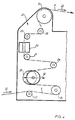
- a deflection and support roller 23 In the inlet part 21 of this treatment machine - viewed in the transport direction (arrow 22) of the textile web T to be treated - one after the other or one above the other, a deflection and support roller 23, a feed roller 24, a straightening roller 25 in one of the above-described embodiments with a plurality of roller parts and also one Spreader roller 26, a deflection roller 27, an optical sensor device 28 for determining the alignment state of the textile web T, a deflection roller 29, a further spreader roller 30 and a simple feed roller 31 are provided, from which the textile web T can be supplied with tensioning chains or the like.
- a special feature here is also thought of keeping the straightening roller 25, which is divided into individually drivable roller parts, diagonally adjustable, as indicated in FIG. 4 and symbolized by a double arrow 32.
- the straightening roller 25 can thus be adjusted in its entirety, so that in addition to the straightening work which can be achieved by the individual roller parts, particularly large diagonal distortions of
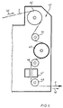
- FIG. 5 shows a modification of the installation option previously described with reference to FIG. 4 in the inlet part 21 'of a similar textile web treatment machine.
- a deflection or support roller 33 in the inlet part 21 '- again in the direction of travel (arrow 22) of the textile material T - one behind the other or one above the other, a deflection or support roller 33, a straightening roller 34 designed according to the invention (roughly corresponding to the example according to FIGS. 1 and 2 ), a first diagonal straightening roller 35, a first spreader roller 36, a second diagonal straightening roller 37 and - similar to the previous example (FIG.
- the straightening device according to the invention into the outlet part 41 of a textile web treatment machine, in particular as a stenter dryer and / or fixing machine, regardless of the design of the inlet part of a textile web treatment machine, as shown in FIG 6 is indicated schematically.
- This straightening device is arranged behind a pull-out roller 42 of this treatment machine. Under or behind this pull-out roller 42 are then - viewed in the running direction (arrow 43) of the textile material T - successively a deflection roller 44, a split-leveling roller 45 designed according to the invention (roughly corresponding to the explanations above according to FIGS.
- the position of the weft threads can be determined with the help of the optical sensor device.
- These optical sensor devices are expediently - as shown and explained with reference to FIGS. 4 to 6 - arranged in the running direction of the textile web T behind the respective straightening roller or the last straightening roller. Deviations from the desired undistorted weft position are used by automatic control of the diagonal straightening rollers and the individual drives for the roller parts of the straightening roller to correct these advantages.
- two or more such rollers or leveling rollers which are divided into individually driven roller parts, are provided in the inlet part of a textile web treatment machine or a separately adjustable leveling device, then the total straightening work to be carried out on a warped textile web is divided into two or more such divided straightening rollers, which makes it possible to achieve a particularly gentle, to a certain extent, multi-stage alignment of the detected textile web distortions, which is particularly advantageous for larger textile web distortions.
- control signals derived from the measuring or sensor devices and control devices can be determined by the number of available divided straightening rollers are divided, each sub-straightening roller then being supplied with a partial actuating signal corresponding to the manipulated variable to be regulated.
Landscapes
- Engineering & Computer Science (AREA)
- Textile Engineering (AREA)
- Chemical & Material Sciences (AREA)
- Materials Engineering (AREA)
- Treatment Of Fiber Materials (AREA)
- Spinning Or Twisting Of Yarns (AREA)
- Looms (AREA)
Claims (21)
- Dispositif de redressement d'étirages dans une nappe de produit textile, comprenant au moins un rouleau dresseur dont l'enveloppe est subdivisée en direction axiale en plusieurs parties dont chacune est commandée séparément et à vitesse de rotation variable et qui sont supportées rotatives sur un corps fixe de support qui passe dans la direction de l'axe dans le rouleau dresseur, caractérisé en ce que des trains d'engrenage séparés (2, 3) sont disposés à l'intérieur de chaque partie de rouleau (1a à 1d) réalisée sous la forme d'un cylindre creux, chacun de ces trains d'engrenage comprenant un arbre de commande (4a à 4d) passant par une extrémité frontale (1L, 1R) du rouleau dresseur (1) et se prolongeant vers l'extérieur, cet arbre de commande étant relié à une commande extérieure séparée (5a à 5d) prévue au voisinage de cette extrémité frontale du rouleau et dont la vitesse de rotation est variable, chaque arbre de commande étant parallèle à et placé à distance radiale du corps fixe de support (6).
- Dispositif selon la revendication 1, caractérisé en ce que chaque train d'engrenage est un train d'engrenage droit (2, 3) qui comprend un pignon de commande (2) disposé à l'extrémité intérieure (4a' à 4d') de l'arbre de commande (4a à 4d), ainsi qu'une couronne (3) à denture intérieure qui est en prise avec ce pignon et qui est prévue sur la circonférence intérieure de la partie correspondante du rouleau (1a à 1d).
- Dispositif selon la revendication 1, caractérisé en ce que certaines des commandes extérieures (5a à 5d) des parties de rouleau (1a à 1d) sont disposées sur un côté extrême du rouleau (1L) et les autres sont disposées sur le second côté extrême opposé (1R) du rouleau, les arbres de commande (4a à 4d) allant du train d'engrenage correspondant (4a à 4d) vers l'extrémité frontale la plus proche du rouleau et tous les arbres de commande passant par la même partie du rouleau étant disposés à distance circonférentielle les uns des autres autour de l'axe longitudinal (LA) du rouleau.
- Dispositif selon la revendication 1, caractérisé en ce que le corps fixe de support (6) supporte au moins un flasque (7) qui lui est fixé à l'intérieur de chaque partie de rouleau, la partie correspondante du rouleau étant montée librement rotative sur la circonférence extérieure de ce flasque et un trou (9) de passage de chaque arbre de commande (4a à 4d) passant par cette partie de rouleau étant prévu dans ce flasque, un palier (10) de support d'au moins l'arbre de commande aboutissant dans la partie correspondante du rouleau étant disposé dans le trou de passage (9).
- Dispositif selon la revendication 4, caractérisé en ce qu'un palier de roulement (8) est disposé entre la circonférence extérieure de chaque flasque (7) et la circonférence intérieure de la partie correspondante de rouleau (1a à 1d).
- Dispositif selon la revendication 4, caractérisé en ce que chaque palier de support d'un arbre de commande est formé essentiellement d'un palier de roulement (10) placé sensiblement dans le trou correspondant de passage (9).
- Dispositif selon la revendication 4, caractérisé en ce que le corps fixe de support est formé d'un tube de support (6) et les arbres de commande (4a à 4d) passent à l'intérieur de ce tube de support, les arbres de commande étant montés rotatifs à proximité de la circonférence intérieure du tube de support et les pignons de commande (2) disposés sur les extrémités internes (4a à 4d) de ces arbres passant par un trou en forme de fenêtre (11) qui est prévu dans la paroi du tube de support et ressortant radialement de ce trou sur une distance suffisante pour qu'ils soient en prise avec la couronne (3) à denture intérieure de la partie correspondante de rouleau (1a à 1d).
- Dispositif selon la revendication 4, caractérisé en ce que les arbres de commande (4'c) des parties de rouleau (1'a, 1'c) passent dans un espace (13) de section annulaire situé entre le corps fixe de support (12) et la circonférence intérieure des parties de rouleau, les flasques (14) étant fixés sur la circonférence extérieure du corps fixe de support.
- Dispositif selon la revendication 4, caractérisé en ce qu'une partie intermédiaire de rouleau (1'b) qui est relativement courte en direction axiale et qui est disposée entre toutes les deux parties voisines commandées de rouleau (1'a et 1'c) est montée librement rotative, indépendamment des parties commandées du rouleau, sur un flasque correspondant (14) porté par le corps fixe de support (12).
- Dispositif selon la revendication 1, caractérisé en ce que toutes les parties commandées (1a à 1d) du rouleau dresseur ont une même longueur axiale.
- Dispositif selon la revendication 1, caractérisé en ce qu'au moins certaines des parties commandées du rouleau dresseur (1) ont des longueurs axiales qui diffèrent.
- Dispositif selon la revendication 1, dans lequel au moins un rouleau d'amenée et un rouleau d'alimentation sont disposés à distance l'un derrière l'autre dans le sens de transport de la nappe (T) de produit textile dans un bâti commun, caractérisé en ce que le rouleau dresseur (25) est disposé entre le rouleau d'amenée (24) et le rouleau d'alimentation (31).
- Dispositif selon la revendication 12, caractérisé en ce que le rouleau d'amenée et le rouleau d'alimentation sont subdivisés axialement de la même manière que le rouleau dresseur en parties dans chacune desquelles des commandes séparées sont montées, chacune de ces parties de rouleau étant équipée d'une roue libre tournant dans le sens avant.
- Dispositif selon la revendication 1, dans lequel au moins un rouleau d'amenée et un rouleau d'alimentation sont disposés à distance l'un derrière l'autre, dans le sens de transport de la nappe (T) de produit textile, dans un bâti commun, caractérisé en ce que le rouleau d'amenée et le rouleau d'alimentation sont tous deux réalisés de la même manière en rouleau dresseur subdivisé axialement plusieurs fois et dans chacune des parties duquel sont montés des trains d'engrenage séparés.
- Dispositif selon la revendication 1, caractérisé en ce que ce dispositif est réalisé en machine individuelle montée séparément.
- Dispositif selon la revendication 1, caractérisé en ce qu'il est intégré dans la partie d'entrée (21, 21') d'une machine de traitement d'une nappe de produit textile constituée en particulier d'une rame sécheuse et/ou de fixage et les commandes des parties de chaque rouleau dresseur (25, 34) coopèrent avec des dispositifs correspondants d'alimentation d'organes de transport en la nappe de produit textile.
- Dispositif selon la revendication 16, caractérisé en ce que la position de chaque rouleau dresseur subdivisé (25) intégré dans la partie d'entrée (21) d'une machine de traitement d'une nappe de produit textile est réglable indépendamment en diagonale.
- Dispositif selon la revendication 16, caractérisé en ce qu'au moins un cylindre de redressement en diagonale (35, 37) et/ou au moins un rouleau élargisseur (36, 26) est disposé devant et/ou derrière chaque rouleau dresseur subdivisé (34).
- Dispositif selon la revendication 1, caractérisé en ce qu'il est intégré dans la partie de sortie (41) d'une machine de traitement d'une nappe de produit textile réalisée en particulier sous la forme d'une rame sécheuse et/ou de fixage, le rouleau dresseur (45) subdivisé en parties commandées individuellement étant disposé derrière un cylindre délivreur (42) de la machine proprement dite de traitement.
- Dispositif selon la revendication 1, caractérisé en ce qu'il est intégré dans la partie de sortie d'une machine de traitement d'une nappe de produit textile constituée en particulier d'une rame sécheuse et/ou de fixage, le rouleau dresseur subdivisé en parties commandées individuellement formant également le cylindre délivreur de la machine proprement dite de traitement.
- Dispositif selon l'une des revendications 16, 19 ou 20, caractérisé en ce qu'un dispositif capteur optique (28, 47) de détection de l'état de redressement de la nappe de produit textile (T) est disposé derrière le rouleau dresseur subdivisé (25, 34, 45) - par rapport au sens de défilement (22, 43) de la nappe de produit textile (T).
Priority Applications (1)
| Application Number | Priority Date | Filing Date | Title |
|---|---|---|---|
| AT90114497T ATE90746T1 (de) | 1989-08-10 | 1990-07-27 | Vorrichtung zum richten von verzuegen in einer textilbahn. |
Applications Claiming Priority (2)
| Application Number | Priority Date | Filing Date | Title |
|---|---|---|---|
| DE3926515 | 1989-08-10 | ||
| DE3926515A DE3926515A1 (de) | 1989-08-10 | 1989-08-10 | Vorrichtung zum richten von verzuegen in einer textilbahn |
Publications (2)
| Publication Number | Publication Date |
|---|---|
| EP0412376A1 EP0412376A1 (fr) | 1991-02-13 |
| EP0412376B1 true EP0412376B1 (fr) | 1993-06-16 |
Family
ID=6386908
Family Applications (1)
| Application Number | Title | Priority Date | Filing Date |
|---|---|---|---|
| EP90114497A Expired - Lifetime EP0412376B1 (fr) | 1989-08-10 | 1990-07-27 | Installation pour rectifier les fils de trame d'un tissu |
Country Status (4)
| Country | Link |
|---|---|
| EP (1) | EP0412376B1 (fr) |
| AT (1) | ATE90746T1 (fr) |
| DE (2) | DE3926515A1 (fr) |
| ES (1) | ES2042154T3 (fr) |
Families Citing this family (8)
| Publication number | Priority date | Publication date | Assignee | Title |
|---|---|---|---|---|
| JP2980637B2 (ja) * | 1990-03-31 | 1999-11-22 | 株式会社土谷製作所 | 緯糸矯正機 |
| DE4141779A1 (de) * | 1991-12-18 | 1993-06-24 | Krantz H Gmbh & Co | Vorrichtung zum egalisieren einer warenbahn |
| US5825652A (en) * | 1995-09-08 | 1998-10-20 | Gerber Garment Technology, Inc. | Sample garment making system |
| EP1357219A3 (fr) * | 2002-04-24 | 2004-04-07 | Mahlo GmbH & Co. KG | Procédé et dispositif pour transporter et simultanément rectifier en continu les distorsions des fils ou des mailles dans les bandes textiles |
| DE202004012118U1 (de) | 2004-08-03 | 2005-12-22 | Ise Innomotive Systems Europe Gmbh | Insassen-Schutzeinrichtung für ein Kraftfahrzeug |
| DE202006007586U1 (de) * | 2006-01-24 | 2006-08-17 | Brückner Trockentechnik GmbH & Co. KG | Vorrichtung zum Richten textiler Materialbahnen |
| CN113564854B (zh) * | 2021-08-16 | 2023-02-03 | 浙江绍兴永利印染有限公司 | 一种多功能布料调整装置 |
| CN113846477B (zh) * | 2021-11-19 | 2022-08-26 | 绍兴金楚印染有限公司 | 一种针对纺织面料非合理纬弯进行整理的纠正机构 |
Family Cites Families (12)
| Publication number | Priority date | Publication date | Assignee | Title |
|---|---|---|---|---|
| DE1131635B (de) * | 1959-03-10 | 1962-06-20 | Martini & Cie | Vorrichtung zum Geraderichten verzogener Schussfaeden |
| DE1113437B (de) * | 1960-03-08 | 1961-09-07 | Famatex G M B H | Vorrichtung zum Richten von Schussfaeden in Gewebebahnen |
| FR1348240A (fr) * | 1963-02-22 | 1964-01-04 | Erhardt & Leimer Ohg | Dispositif pour rectifier les fils de trame |
| DE1460568A1 (de) * | 1965-06-15 | 1969-02-06 | Erhardt & Leimer Ohg | Unterteilte Ausrollwalze fuer textile Warenbahnen |
| DE2007359C3 (de) * | 1970-02-18 | 1975-10-02 | Brueckner-Trockentechnik Kg, 7250 Leonberg | Vorrichtung zur Behandlung von Textilbahnen mit einem umlaufenden Transportorgan |
| FR2142289A5 (en) * | 1971-06-14 | 1973-01-26 | Mount Hope Machinery Ltd | Web dressing machine - has rollers for correcting - alignment and orientation of knit or weave |
| GB1346196A (en) * | 1971-06-16 | 1974-02-06 | Wittler Co H | Curved width stretching roller for flexible webs of material of fabric paper or foils |
| DE2261861A1 (de) * | 1972-12-18 | 1974-06-27 | Wittler & Co H | Breitstreckwalze fuer biegsame textil-, papier- oder kunststoffbahnen |
| FR2163300A5 (en) * | 1972-12-29 | 1973-07-20 | Brueckner Trockentechnik Kg | Stretching device - for removing deformations in a textile web being advanced to a processing machine |
| AT365984B (de) * | 1977-02-24 | 1982-02-25 | Zimmer Peter Ag | Geraderichtvorrichtung |
| GB2071625B (en) * | 1980-03-11 | 1983-09-21 | Eberlin Edgar Anthony | Device for spreading or tensioning a moving sheet or web |
| DE3715086A1 (de) * | 1986-11-14 | 1988-05-26 | Mahlo Gmbh & Co Kg | Verfahren und vorrichtung zum richten von schussfaeden in geweben |
-
1989
- 1989-08-10 DE DE3926515A patent/DE3926515A1/de not_active Withdrawn
-
1990
- 1990-07-27 ES ES199090114497T patent/ES2042154T3/es not_active Expired - Lifetime
- 1990-07-27 EP EP90114497A patent/EP0412376B1/fr not_active Expired - Lifetime
- 1990-07-27 DE DE9090114497T patent/DE59001767D1/de not_active Expired - Fee Related
- 1990-07-27 AT AT90114497T patent/ATE90746T1/de not_active IP Right Cessation
Also Published As
| Publication number | Publication date |
|---|---|
| EP0412376A1 (fr) | 1991-02-13 |
| ATE90746T1 (de) | 1993-07-15 |
| DE3926515A1 (de) | 1991-02-14 |
| ES2042154T3 (es) | 1993-12-01 |
| DE59001767D1 (de) | 1993-07-22 |
Similar Documents
| Publication | Publication Date | Title |
|---|---|---|
| DE9304846U1 (de) | Abzugsvorrichtung | |
| DE3316656A1 (de) | Vorrichtung zum oe-friktionsspinnen | |
| DE19833509B4 (de) | Rundstrickmaschine mit einer Zugvorrichtung für Strickware | |
| EP0412376A1 (fr) | Installation pour rectifier les fils de trame d'un tissu | |
| DE2505516B2 (de) | Führungsvorrichtung für eine Zigarettenstrangm aschine | |
| DE4008897C2 (fr) | ||
| EP0412375B1 (fr) | Installation pour rectifier les fils de trame d'un tissu | |
| DE2233095A1 (de) | Transportvorrichtung fuer bandfoermige aufzeichnungstraeger | |
| CH706351A1 (de) | Abtragwalze. | |
| DE3535068A1 (de) | Foerderwalzenanordnung | |
| DE2828535C2 (de) | Vorrichtung zum fortlaufenden Ablegen eines Garnes | |
| EP4033047B1 (fr) | Installation de protection solaire avec un système de traction | |
| DE3133149A1 (de) | Legemaschine | |
| DE2040494B2 (de) | Sammel und falzzylinder fuer falzapparate von rotations druckmaschinen | |
| DE1921344A1 (de) | Kerneinspannvorrichtung | |
| EP0228542B1 (fr) | Dispositif d'entraînement à courroie, par exemple pour des dispositifs d'alimentation en fil pour des machines textiles | |
| DE69204858T2 (de) | Verfahren und Vorrichtung zum Walzformen von Streifenmaterial. | |
| DE19733266A1 (de) | Antriebsrolle für eine Fadenliefervorrichtung | |
| DE19853869A1 (de) | Vorrichtung zur Strangführung und damit ausgerüstete Rundflechtmaschine | |
| DE3931997A1 (de) | Antriebsrolle fuer eine fadenliefervorrichtung | |
| DE3925959A1 (de) | Synchronmotor, vorzugsweise elektronisch kommutierter, permanentmagneterregter servomotor | |
| DE3613859C2 (fr) | ||
| DE1477897C3 (de) | Werkstuckspindelantrieb fur einen Mehrspindel Drehautomaten | |
| DE19814927A1 (de) | Antriebsrolle, insbesondere für den Antriebsriemen einer Fadenliefervorrichtung an einer Textilmaschine | |
| DE2040494C (de) | Sammel und Falzzylinder fur Falz apparate von Rotationsdruckmaschinen |
Legal Events
| Date | Code | Title | Description |
|---|---|---|---|
| PUAI | Public reference made under article 153(3) epc to a published international application that has entered the european phase |
Free format text: ORIGINAL CODE: 0009012 |
|
| AK | Designated contracting states |
Kind code of ref document: A1 Designated state(s): AT DE ES FR GB IT |
|
| 17P | Request for examination filed |
Effective date: 19910404 |
|
| 17Q | First examination report despatched |
Effective date: 19921208 |
|
| GRAA | (expected) grant |
Free format text: ORIGINAL CODE: 0009210 |
|
| AK | Designated contracting states |
Kind code of ref document: B1 Designated state(s): AT DE ES FR GB IT |
|
| REF | Corresponds to: |
Ref document number: 90746 Country of ref document: AT Date of ref document: 19930715 Kind code of ref document: T |
|
| ITF | It: translation for a ep patent filed | ||
| REF | Corresponds to: |
Ref document number: 59001767 Country of ref document: DE Date of ref document: 19930722 |
|
| GBT | Gb: translation of ep patent filed (gb section 77(6)(a)/1977) |
Effective date: 19930813 |
|
| ET | Fr: translation filed | ||
| REG | Reference to a national code |
Ref country code: ES Ref legal event code: FG2A Ref document number: 2042154 Country of ref document: ES Kind code of ref document: T3 |
|
| PLBE | No opposition filed within time limit |
Free format text: ORIGINAL CODE: 0009261 |
|
| STAA | Information on the status of an ep patent application or granted ep patent |
Free format text: STATUS: NO OPPOSITION FILED WITHIN TIME LIMIT |
|
| 26N | No opposition filed | ||
| PGFP | Annual fee paid to national office [announced via postgrant information from national office to epo] |
Ref country code: FR Payment date: 19980611 Year of fee payment: 9 |
|
| PGFP | Annual fee paid to national office [announced via postgrant information from national office to epo] |
Ref country code: AT Payment date: 19980616 Year of fee payment: 9 |
|
| PGFP | Annual fee paid to national office [announced via postgrant information from national office to epo] |
Ref country code: GB Payment date: 19980623 Year of fee payment: 9 |
|
| PGFP | Annual fee paid to national office [announced via postgrant information from national office to epo] |
Ref country code: ES Payment date: 19980709 Year of fee payment: 9 |
|
| PGFP | Annual fee paid to national office [announced via postgrant information from national office to epo] |
Ref country code: DE Payment date: 19980922 Year of fee payment: 9 |
|
| PG25 | Lapsed in a contracting state [announced via postgrant information from national office to epo] |
Ref country code: GB Free format text: LAPSE BECAUSE OF NON-PAYMENT OF DUE FEES Effective date: 19990727 Ref country code: AT Free format text: LAPSE BECAUSE OF NON-PAYMENT OF DUE FEES Effective date: 19990727 |
|
| PG25 | Lapsed in a contracting state [announced via postgrant information from national office to epo] |
Ref country code: ES Free format text: LAPSE BECAUSE OF NON-PAYMENT OF DUE FEES Effective date: 19990728 |
|
| PG25 | Lapsed in a contracting state [announced via postgrant information from national office to epo] |
Ref country code: FR Free format text: THE PATENT HAS BEEN ANNULLED BY A DECISION OF A NATIONAL AUTHORITY Effective date: 19990731 |
|
| GBPC | Gb: european patent ceased through non-payment of renewal fee |
Effective date: 19990727 |
|
| PG25 | Lapsed in a contracting state [announced via postgrant information from national office to epo] |
Ref country code: DE Free format text: LAPSE BECAUSE OF NON-PAYMENT OF DUE FEES Effective date: 20000503 |
|
| REG | Reference to a national code |
Ref country code: FR Ref legal event code: ST |
|
| REG | Reference to a national code |
Ref country code: ES Ref legal event code: FD2A Effective date: 20020603 |
|
| PG25 | Lapsed in a contracting state [announced via postgrant information from national office to epo] |
Ref country code: IT Free format text: LAPSE BECAUSE OF NON-PAYMENT OF DUE FEES Effective date: 20050727 |