EP0412431A2 - Verfahren und GerÀ¤t zum Sortieren von Teilchen mit einem beweglichen Auffangrohr - Google Patents
Verfahren und GerÀ¤t zum Sortieren von Teilchen mit einem beweglichen Auffangrohr Download PDFInfo
- Publication number
- EP0412431A2 EP0412431A2 EP90114804A EP90114804A EP0412431A2 EP 0412431 A2 EP0412431 A2 EP 0412431A2 EP 90114804 A EP90114804 A EP 90114804A EP 90114804 A EP90114804 A EP 90114804A EP 0412431 A2 EP0412431 A2 EP 0412431A2
- Authority
- EP
- European Patent Office
- Prior art keywords
- particles
- catcher tube
- tube
- analysis
- analysis portion
- Prior art date
- Legal status (The legal status is an assumption and is not a legal conclusion. Google has not performed a legal analysis and makes no representation as to the accuracy of the status listed.)
- Granted
Links
Images


Classifications
-
- G—PHYSICS
- G01—MEASURING; TESTING
- G01N—INVESTIGATING OR ANALYSING MATERIALS BY DETERMINING THEIR CHEMICAL OR PHYSICAL PROPERTIES
- G01N15/00—Investigating characteristics of particles; Investigating permeability, pore-volume or surface-area of porous materials
- G01N15/10—Investigating individual particles
- G01N15/14—Optical investigation techniques, e.g. flow cytometry
- G01N15/1404—Handling flow, e.g. hydrodynamic focusing
-
- G—PHYSICS
- G01—MEASURING; TESTING
- G01N—INVESTIGATING OR ANALYSING MATERIALS BY DETERMINING THEIR CHEMICAL OR PHYSICAL PROPERTIES
- G01N15/00—Investigating characteristics of particles; Investigating permeability, pore-volume or surface-area of porous materials
- G01N15/10—Investigating individual particles
- G01N15/14—Optical investigation techniques, e.g. flow cytometry
- G01N15/149—Optical investigation techniques, e.g. flow cytometry specially adapted for sorting particles, e.g. by their size or optical properties
Definitions
- the present invention relates to a catcher tube sorter system for a particle flow through apparatus which includes a catcher tube selectively alignable with the flow from the apparatus, and more particularly, concerns a flow cytometer for determining one or more characteristics of particles flowing through the cytometer with such a catcher tube sorter to provide separation of the particles according to the determined characteristics.
- the method of sorting with a positionable catcher tube is also a part of the present invention.
- FACScanTM instrument sold by Becton Dickinson Immunocytometry Systems, San Jose, California.
- the FACScanTM instrument rapidly analyzes cells on the basis of fluorescence and light scatter properties. Analysis is accomplished by introducing cells in suspension to the center of a focused liguid stream thus causing them to pass, one at a time, through a focused light from a high power laser. Each cell is individually characterized by its light scatter signals and by the intensity and color of fluorescence emitted while it is illuminated.
- a sheath livid focuses the particles or cells as they pass through the orifice associated with the analyzing or counting capabilities.
- U.S. Patent Nos. 4,503,385 and 4,526,276 describe particle analysis systems in which particles flowing in a stream are enveloped in a sheath livid which focuses and confines the sample liquid (with the particles or cells) to the center of the flowing stream.
- U.S. Patent No. 4,110,604 describes a particle density measuring system in which particles flowing in a stream are enveloped in a sheath liguid which focuses and confines the sample fluid (with the particles) to the center of the flowing stream.
- Particle sorters of the type relying upon electrostatic separation of particles are described in U.S. Patent Nos. 3,380,584; 3,710,933; 3,826,364; 4,148,718; 4,230,558; and 4,138,480.
- the particle sorters which rely upon an electrostatic field for separating and sorting particles have particles charged with the same electrical polarity accumulate in respective collection wells. The result is that the collection well itself assumes the electrical polarity of the particles being collected. Once this electrical charge of the collection well is established, incoming particles of the same polarity are deflected because of the electrostatic force operating to separate charges of like nature. Removing the charge by a ground wire in the collection vessel is known.
- These sorters may produce aerosols which must be contained to avoid biological hazards to nearby personnel when sorting pathogenic particles.
- U.S. Patent No. 4,175,662 includes a method and apparatus for sorting of particles or cells in accordance with their physical or chemical properties where sorting is achieved after the particles are analyzed by reliance upon an electrolysis gas pressure impulse which causes a deflection of the particle suspension stream and flow into a different channel.
- This sorter may cause disturbances to the particle flow thru the laser beam thus interfering with the optical analysis of the particles.
- a preferred form of the present invention includes a catcher tube sorter for a flow cytometer with a body member and passageway for particles to be analyzed.
- the passageway has an analysis portion, a pre-analysis portion and a post analysis portion.
- An uptake tube is connected in fluid communication with the pre-analysis portion and adapted for fluid communication with a source of particles containing samples of particles for providing a flow path from the source of particles into the flow cytometer analysis portion.
- a catcher tube is carried on the body member and is mounted so it may be selectively positionable in fluid communication with the analysis portion for intermittently receiving analyzed particles after passage of the particles through the flow cytometer analysis portion.
- An operator receives an input signal from the analysis portion relative to one or more particle characteristics and then moves the catcher tube into fluid communication with the flow cytometer analysis portion.
- a sheathing liquid is introduced into the pre-analysis portion about the uptake tube inner end to provide a sheathed flow of particles along an axis of the passageway toward the analysis portion.
- the flow cytometer may have a flowcell having an orifice sized to permit the passage of substantially one particle at a time through the analysis portion such that the input signal is an optical response to one or more particle characteristics.
- the post analysis portion is arranged about the catcher tube to receive and draw away particle flow not selectively caught in the catcher tube.
- the input signal is a pulse of strength and duration sufficient to selectively position the catcher tube in fluid communication with the analysis portion.
- a driver mounted to the body member and associated with the catcher tube receives the input signal pulse and selectively positions the catcher tube in at least partial alignment for fluid communication with the analysis portion.
- the catcher tube has an axis and is carried on the body member for movement of its axis into at least partial alignment with the analysis portion.
- a catcher tube sorter for a particle flow through apparatus comprises a body member having a passageway therethrough including an analysis region through which substantially one particle at a time may pass in the direction of flow when the apparatus is operating.
- a supply of particles connected in fluid communication with the passageway provide the analysis region with substantially one particle at a time.
- a sheathing liquid is applied to the supply of particles in the passageway for hydrodynamically focusing the particles relative to the liquid.
- a catcher tube means is preferably supported upon the body member for fluid communication with particles from the analysis region.
- the catcher tube means is positionable to a position substantially in alignment with the particle flow from the analysis region from a position where the catcher tube means is aligned with the particle-free flow from the analysis region.
- a control means operatively responds to particles of one or more preselected types passing through the analysis region. The control means may be arranged for moving the catcher tube between the positions substantially into and out of alignment with the particle flow.
- the catcher tube means may include a resilient support which is stressed upon movement of the catcher tube means between positions.
- the control means is responsive to at least one characteristic of one or more particles passing through the analysis region for activating a driver in the control means thereby flexing the resilient support.
- the passageway has an analysis portion, a pre-analysis portion and post-analysis portion disposed along an axis.
- An uptake tube has an inner end positioned in the pre-analysis portion of the passageway near the analysis portion and an outer end extending outwardly of the body member and inserted into a sample supply containing liguid and particles.
- the uptake tube has a lumen extending therethrough for the passage of the particles toward the analysis portion.
- a flowcell with an orifice sized to permit the passage of substantially one particle at a time is included in the analysis portion.
- In the post analysis portion there is a catcher tube sorter mounted for selective alignment with an exit from the flow cell.
- a catcher tube is moved, in response to regulating means, into fluid communication with the analysis portion by substantially aligning the catcher tube and an axis through the analysis portion.
- the catcher tube is preferably elongate relative to its axis and a flexible support attaches the catcher tube to the body member for carrying the catcher tube in a position for realignment of the catcher tube axis with the passageway axis so that the axes are substantially parallel to one another.
- the elongate catcher tube includes a pair of ends and a central section therebetween and the flexible support is mounted between the central section of the catcher tube and the body member thus permitting pivotal movement of the catcher tube about a point along the axis of the catcher tube.
- the catcher tube swings into an axial alignment substantially parallel with the particles passing one at a time in a stream, from the flow cell and in alignment with the passageway axis so the the axes are coaxially in line with one another.
- the catcher tube has a driver located between one end of the catcher tube and the body member for moving the opposite end into coaxial alignment with the particle stream.
- a method for sorting particles passing through a particle analysis apparatus is another form of the invention wherein a sample of particles carried in a liquid is transported by air pressure applied to the liquid.
- the method includes generating a signal representative of one or more characteristics of the particles passing through an analysis region of the analysis apparatus and applying the signal to a driver for changing the position of a catcher tube so that the catcher tube is moved to receive the particles having one or more characteristics.
- the step of applying the signal to the driver for changing the position of the catcher tube may include flexing a support for the catcher tube to bring the catcher tube into substantial alignment with the particles passing through the particle analysis apparatus and which particles have one or more of the characteristics sought to be sorted.
- the step of generating a signal representative of one or more characteristics of the particles passing through an analysis region may include using light to analyze the particles passing one at a time through the analysis region to provide an electrical signal.
- the step of using light to analyze the particles passing one at a time through the analysis region to provide a signal may include the step of applying the signal to a driver for changing the position of the catcher tube.
- the step of flexing a support for the catcher tube to align the catcher tube with the particles may include pivoting the catcher tube about a point.
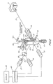
- Apparatus 10 for example, may be a cell analyzer which includes a liquid sampling console 12 which is constructed to contain particle or cell detection and analysis elements as hereinafter described.
- apparatus 10 includes a liquid sampling console 12 which is constructed to contain the particle, light scatter and fluorescence measuring components, as hereinafter described, but which is separate from the analysis console 13.
- Analysis console 13 includes the electrical components, display screens and other data information regarding the control and function of the apparatus 10.
- liquid sampling console 12 as seen in Figure 1, includes a flow manifold assembly in the form of a housing 14 which is designed to provide a stream of flowing liquid containing the particle to be analyzed.
- the particles for analysis may be included in a source of particles or test tube 15 which may be sealably engaged onto housing 14.
- housing 14 Before describing the details of housing 14, a general description of the optical and flow elements of flow cytometry apparatus 10 will be provided.
- optical and particle flow elements of a flow cytometry apparatus 10 are illustrated.
- the optical and flow elements of Figure 2 represent the major components of the flow cytometry apparatus 10 for moving particles, such as cells or the like, in a liquid stream, substantially one at a time, in order to assess those particles for specific characteristics thereof.
- the elements of the device of Figure 2 may be included in a FACScan analyzer, manufactured and sold by Becton Dickinson Immunocytometry Systems, San Jose, California for cytometric study on the basis of light scatter and fluoresence in a wide variety of research laboratory applications.
- the optical and flow elements to be described in more particular detail may be embodied in the FACScan analyzer. It is understood that the present invention is useful in many different types of flow fluorometric or flow cytometry apparatuses, whether measuring light scatter, particle volume, fluorescence or other optical parameters for the identification or quantification of cells or the like in a sample liquid medium.
- a light source 16 such as a laser which provides a linearly polarized collimated beam 17 of light at a singular wavelength or at a number of discreet wavelengths.
- light source 16 may be broad-spectrum arc lamp, such as mercury or xenon, with polarizing means included in excitation light path 18 produced by light source 16.
- apparatus 10 also includes a lens 19 which focuses the light beam 17 at a liquid stream 20 containing the particles or cells under investigation.
- a nozzle incorporated within the flow cytometry apparatus 10 of the present invention, facilitates the flowing of cells or particles within liquid stream 20.
- the use of a nozzle is well-known and is described, for example, in U.S. Pat. No. 3,826,364.
- the nozzle provides a hydrodynamically focused flow of cells in the liquid stream 20 comprising a sheath fluid and particles or cells 68 in Figure 3. As each cell or particle passes through where the focused light beam 17 intersects liquid stream 20, light scattered thereby may be detected.
- light scattered by the cell or particle can be detected by an appropriate silicon photodiode 21.
- fluorescence if emitted by particles energized by the illumination from the light source, can also be detected. Fluorescence emitted by autofluorescent particles or fluorescently labeled or stained particles in the liquid stream 20 can be detected.
- Photodetector 21, as illustrated in Figure 2, is positioned to receive light scattered forwardly by each cell. Fluorescence, if emitted by cells energized by the illumination from the light source 16, may also be detected. similarly, light scattered in different directions, besides the forward direction, may be detected. In laser excited flow cytometry, both fluorescence and wide angle light scatter are typically collected at an angle whose viewing axis is 90° relative to the excitation axis of light beam 17. In Figure 2, axis 22 represents the 90° viewing access for the collection of fluorescence and wide angle scatter. Thus, light traveling along axis 22 includes both light scatter and fluorescence as its components.
- the light scatter and fluorescence should be separated or split.
- dichroic filters or a beam splitter 23 is used to receive both scattered light and fluorescence at the 90° angle and to re-direct each such component in different directions. Such re-direction of light scatter and fluorescence then permits the light scatter and fluorescence to be collected separately, even though both originate at the 90° angle.
- the reflected light scatter may be detected by a photomultiplier tube 24.
- a dichroic mirror 23 may be used to separate the different color wavelengths.
- fluorescence in the green color region may be transmitted by dichroic mirror 23 along axis 26 and collected in an appropriate photodetector 27.
- Additional dichroic mirrors may be included as in United States Patent 4,662,742 for associating the fluorescence colors with additional characteristics of cells or particles analyzed.
- lenses, filters, barriers or the like may be employed in conjunction with each additional photodetector to obtain as pure a signal as possible. Obtaining such optically clean signals is most desirable particularly when fluorescence and light scatter channels are used, as in the apparatus illustrated in Figure 2.
- the electrical signals from photodetectors 21, 24, and 27 are typically fed as discrete pulses to the electronics 28 of the apparatus for purposes of display 29, storage or further processing so that one or more characteristics of the cells or particles under analysis can be determined or sorted as will be described in detail herein.
- Electronics 28 may be included in an analysis console 13, if desired.
- housing 14 includes a body member 30 which, in the embodiment being described, is preferably in the form of a block or rectangular prism. Although not shown in the drawings, the block form of housing 14 facilitates the mounting of the housing within the flow cytometer apparatus 10. Extending through housing 14 is a passageway 32 which is defined by three regions: an analysis portion 32a, a pre-analysis portion 32b, and a post-analysis portion 32c. As seen in Figure 3, the pre-analysis analysis and post-analysis portions of passageway 32 lie on an axis A through body member 30 and are arranged in that order relative to the direction of particle flow indicated by arrows through the passageway 32.
- pre-analysis portion 32b and post-analysis portion 32c of the passageway be axisymmetrical shaped bores extending into body member 30. It is preferred that pre-analysis portion 32b of the passageway be tapered so that it includes tapered walls 34 defining a frustoconical passageway having its narrow end facing toward analysis portion 32a of the passageway.
- Flowcell 35 Preferably positioned within analysis portion 32a of the passageway is a flowcell or flow chamber 35 which facilitates the analysis of cells or particles under investigation.
- Flowcell 35 includes an orifice 36 which is preferably rectangular in cross section and sized to permit the passage of substantially one particle at a time therethrough. As a light beam intersects the region defined by orifice 36, particles pass through the light beam thereby establishing a basis for a light-related signal which can be detected.
- body member 30 of the housing includes a recess 38, as shown in Figure 2, into which lens assembly 19 is positioned so that the lens assembly lies adjacent flowcell 35.
- This type of arrangement suggested by the illustration in Figure 2 is consistent with a technique for providing light energy to interrogate the particles under analysis.
- Light is directed through lens assembly 19 at an angle substantially orthogonal or at a right angle to the aforementioned direction of particle flow through the flowcell.
- Lens assembly 19 can include one or more lenses in a condenser lens assembly for focusing incident light on the particles which pass through orifice 36 and may receive light such as fluorescence from the particles which have been illuminated by the incident light beam 18.
- the present invention contemplates that light from the particles may be detected in any direction with respect to the axis of the incident light beam.
- the appropriate light detectors are positioned at the desired angle for collecting light scattered or emitted by the particles or for detecting light energy absorbed by the particles.
- one or more windows 40 extend through body member 30 into flowcell 35 through which light passes for collection by the photodetector elements.
- body member 30 is sufficiently light transmissive to allow light to pass therethrough in sufficient strength to be detected.
- flowcell 35 be light transmissive and also that the flowcell be removable from body member 30 in the event that it needs cleaning, replacement or change.
- Body member 30 also includes a first channel 42 which is in fluid communication with pre-analysis portion 32b of the passageway.
- Channel 42 in this embodiment, extends through a side block 44 of body member 30 so that this channel is substantially at right angles to the axis A of passageway 32.
- Side block 44 connects with an enlarging conduit which reduces fluid velocity entering the pre-analysis portion 32b and thus reduces the flow disturbances associated with the change in direction of the fluid flow.
- a fluid connector 46 is positioned on side block 44 so that its lumen 48 is in fluid communication with channel 42. It is the purpose of channel 42 to provide a passageway for the introduction of a liquid for sheathing particles which flow into analysis portion 32a of the passageway, and which more specifically flow through flowcell 35.
- the sheath liquid is generally pressurized with air and typically flows through channel 42 at a pressure of between 0.5 and 10 psi and at a rate of 10 to 20 ml. per minute.
- the sheath liquid is usually a saline solution which is substantially particle free so that it does not interfere with the analysis.
- Channel 50 Communicating with post-analysis portion 32c of the passageway is another channel 50 which also extends through body member 30 in the embodiment being described.
- Channel 50 preferably extends at substantially right angles to the axis of passageway 32.
- a fluid connector 52 In fluid communication with channel 50 is a fluid connector 52 having a lumen 54 therethrough. It is the purpose of channel 50 to provide one exit for the passage of particles and liquids out of housing 14 after passing through the analysis portion of the passageway. It can be seen that channel 50 has its interior end 55 preferably open to post-analysis portion 32c of the passageway.
- Uptake tube 58 extends substantially along the axis A of passageway 32 and has an inner end 60 positioned in pre-analysis portion 32b of the passageway. It is preferred that inner end 60 be positioned within tapered walls 34 of the pre-analysis portion so that the inner end 60 of the uptake tube lies in a region at low fluid velocity in the pre-analysis portion 32b of the passageway.
- Uptake tube 58 has its outer end 62 extending outwardly of body member 30.
- the body member of the housing preferably includes a circularly shaped extension 64 through which tube 58 extends before passing outwardly of the body member.
- a seal member 65 or other like element for providing a gas-tight seal, is positioned around circularly shaped extension 64. It can be seen in Figures 3 and 4 that test tube 15 is positioned so that it fits onto extension 64 with seal member 65 facilitating a gas-tight seal between the test tube and extension 64 of the body member.
- Test tube 15 includes sampling liquid 66 and particles 68 to be analyzed. Outer end 62 of the tube extends into sampling liquid 66.
- a channel 72 extends through body member 30 and is in fluid communication with the interior of test tube 15.
- a lumen 75 is in fluid communication with a source of regulated pressurized air or other fluid to serve as a driving force of pressure into the test tube 15 so that sampling liquid 66 and particles 68 may pass through lumen 59 of uptake tube 58.
- the air is delivered through lumen 75 at a slightly higher pressure than that applied to drive the sheath liquid through channel 42.
- the regulated air pressure may be controlled at 5.0 psi or 4.0 psi for a selected high or low flow rate of 1.0 microliters per second, or 0.20 microliters per second, respectively.
- Particles 68 pass out of the inner end of the tube into pre-analysis portion 32b of the passageway.
- the particles and sampling liquid become ensheathed by the sheathing liquid so that the particles pass substantially one at a time through orifice 36 in flowcell 35, as seen in Figure 3.
- the confluence between the sampling liquid (and particles) and the sheath liquid form a coaxial, bi-component stream.
- the sampling liquid containing the particles 68 to be analyzed forms the inner component of the flowing stream.
- the particles are interrogated by light which enters the flowcell through lens assembly 19 so that light-related information may be determined with respect to each particle.
- sampling liquid and sheathing liquid pass through the analysis region of the passageway, flow continues into the post-analysis portion 32c of housing 14.
- a typical sample flow rate is in the range of 0.2 to 1.0 microliters per second of sampling liquid through the sampling tube.
- the air pressure in lumen 75 may be adjusted to control the analysis rate of particles through the flow chamber. Typically, the analysis rate would range between 10 and 1,000 particles per second flowing through the flow cell 35.
- the design of passageway 32 and the positioning of uptake tube 58 therein is intended to offer minimal flow resistance and turbulence to the bi-component stream of liquid as it flows toward flowcell 35.
- FIG. 4 there is a schematic illustration of the control 80 whereby the flow rate of particles 68 is regulated.
- the control 80 includes an air pump 82 connected to a pressure regulator 84 adjusted to provide a head pressure input of about 4.0 psi to the sheath liquid supply reservoir 86.
- the outlet from reservoir 86 is preferably connected to a filter 88 which removes any particulate matter from the sheath liquid as it is transported to the lumen 48 of housing
- Air pump 82 in Figure 4, is also connected to the sample flow control 90 for regulating pressurized air to be used to drive the liquid 66 and particles 68 through uptake tube 58 into pre-analysis portion 32b of housing 14.
- sample flow control 90 regulates the air pressure applied to test tube 15 through lumen 75 so that the pressure is at 4 psi or 5 psi depending upon whether a low or a high flow rate of particles 68 is desired.
- a waste reservoir 92 as part of post-analysis portion 32c is connected to lumen 54 to collect a part of the liquids and particles after they have passed through the passageway 32. The sorted particles are caught as will be explained.
- FIG 3 the details of the catcher tube sorter 93 are shown.
- the schematic diagram of Figure 4 best illustrates the overall system.
- the test tube 15 has the driving air pressure supplied through lumen 75 to move particles through lumen 59 of the uptake tube 58.
- an elongate catcher tube 94 In the post analysis portion 32c just after the analysis portion 32a is an elongate catcher tube 94.
- Catcher tube 94 is positioned to be movable into substantial alignment with the axis A passing upwardly through the uptake tube 58 and through the orifice 36.
- the catcher tube 94 is a capillary tube with a tapered ceramic tip and is movable for substantially parallel and nearly coaxial alignment with the axis A.
- an axis B of the catcher tube 94 is pivotal about a point 95 located between a lower end 96 of the catcher tube 94 and an upper end 97 of the catcher tube 94.
- the catcher tube 94 is a two piece construction.
- the lower end 96 is preferably made of alumina ceramic by Small Precision Tools of Petuluma, California as a nailhead capillary bonding tip model NS-60 with a 150 micron inside diameter at the tip.
- the upper end 97 is a stainless steel support.
- the catcher tube 94 pivots into substantial coaxial alignment with the axis A when driven by the driver 98 shown in Figures 3 and 4, but the catcher tube axis B is only nearly coaxial with axis A, being spaced a small distance C from the axis A when pivoted by the driver 98 to the position shown in Figure 5.
- the 150 micron inside diameter at the inlet, entry, tip or lower end 96 of the catcher tube 94 cooperates with the rectangular orifice of the flowcell 36 which is 180 by 430 microns.
- the width of the orifice of the flowcell 36 is 430 micron. A larger inside diameter would allow the catcher tube to pick up fluid accumulating at the orifice exit containing some of the particles 68.
- the inside diameter of the catcher tube 94 should be equal to or slightly smaller than the minimum dimension across the orifice of the flowcell 36. Obviously if the recirculating fluid at the exit of orifice 36 were replaced by a particle-free fluid the inside diameter of the catcher tube 94 could be larger than the minimum dimension at orifice 36.
- the rectangular shape of the flowcell 36 orifice allows the catcher tube 94 to be positioned off or displaced from the particle stream as illustrated in Figure 6 and still be fully in the sheath fluid exiting the orifice of the flow cell 36. This avoids fluid recirculating at the orifice exit from entering the catcher tube 94 and contaminating the collection conduit and filter with particles present in the recirculating fluid.
- the driver 98 is mounted upon body member 30 and is located such that a bearing 99 on the driver 98 contacts the catcher tube 94 near the upper end 97 for positioning of the catcher tube 94.
- the bearing 99 is a spherical shape that provides point contact with the catcher tube 94 upper end 97. The point contact is such that the force of the driver 98 is applied to the upper end 97 substantially normal to the axis B causing the pivotal motion of the catcher tube 94 about the point 95.
- the driver 98 is in the preferred embodiment a piezo electric device, such as model P-810.20 PZT translator of the Physik Instrumente (PI) GmbH & Co., which responds to an electrical pulse of 100 volts of sufficient strength and duration to produce an extension in length of 30 microns such that the bearing 99 moves relative to the driver 98 and pivots the catcher tube 94 into substantial alignment with axis A.
- the circuitry for the driver 98 controls the maximum values of applied voltage and current as well as their time rate of change producing desired position, velocity, acceleration and damping for the sorting, fluidics, and characteristics of the driver 98.
- the preferred driver 98 has a rated stiffness of 6 N/micron with a resonance frequency of 15 KHz and an electrical capacitance of 0.8 microfarad.
- the catcher tube 94 is designed to have a low mass and a high stiffness to achieve a high resonance frequency. In the preferred embodiment the catcher tube 94 has a resonance frequency of about 20 KHZ.
- the driver 98 and catcher tube 94 as a combined mass have a resonance frequency of about 7 KHZ.
- the pulse used to activate driver 98 is obtained after the analysis of the particles 68 as with the detector 24 which is described herein in connection with Figures 1, 2 and 3. Suitable amplification or modification of the activating pulse is within the skill of practitioners and is therefore not set forth in detail.
- the preferred translator can be driven at a peak rate of about 1000 times/second by charging and discharging it like a capacitor.
- a leaf spring 100 is mounted on body member 30 across from bearing 99 and urges the upper end 97 of the catcher tube 94 against the bearing 99. Wires are shown extending from driver 98 for electrical connection in circuit with electronics 28 for the described operation.
- a time delay of about 600 microseconds is provided to allow for the particle 68 to travel from where it is detected by the laser to the catcher tube 94 prior to energization of the driver 98. This time delay provides for transit time of the particle 68.
- driver 98 is energized at about 500 microseconds and de-energized at about 700 microseconds after a desired particle has passed thru the laser beam and been detected.
- the electronics 28 can be used to vary the time delay automatically to compensate for variations in particle stream velocity due to changes in fluid temperature, pressure on the supply tank 26 or back pressure in the post analysis portion. This may be done by measuring the transit time of the particle 68 through the laser beam and using that time to set the delay time.
- Point 95 may be placed anywhere between the ends 96 and 97 but location of the point 95 closer to bearing 99 is preferred to amplify the 30 micron motion of the driver 98 to obtain in excess of 100 microns of motion at catcher tube end 96 as shown in the Figures 3, 4, 5 and 6.
- a resilient support 101 in the form of a flexible thin metallic diaphragm spans the space between the body member 30 and the catcher tube 94 at the level of point 95 and permits the described pivotal movement of the axis B.
- the preferred resilient flanged support 101 is made of a spring material such as beryllium copper or the like and is about 0.25 mm. thick whereby flexure about point 95 causes moderate stress in the resilient support 101 and requires very little force from driver 98.
- the flexure is about .005 radian angular excursion producing a bending stress of about 70,000 psi in the diaphragm of resilient support 101.
- the inertia of the system is therefore minimal and the resonant frequency is high permitting rapid movement of the catcher tube 94 so it is positionable to capture and thereby selectively sort, as will be explained, the desired particles from those particles 68 which have passed through the analysis orifice 36.
- FIG 3 the preferred configuration of the resilient support 101 is shown partially in section.
- a pair of upstanding flanges 102 provide the mounting of the resilient support 101 to the body member 30; only one of the upstanding flanges appears in the partial sectional view of Figure 3.
- the catcher tube 94 upper end 97 to which the the resilient support 101 is connected is stainless steel attaching the beryllium copper of the resilient support is best performed by a pair of press fit metal rings 103.
- the rings 103 are placed around the central section of the catcher tube 94 with the resilient support 101 captured as in a sandwich between the rings 103.
- the lower end 96 of the catcher tube 94 is preferably tapered so that the function of the catcher tube 94 when aligned as described will cleanly separate the particles 68 during sorting.
- the positioning of the lower end 96 within the post analysis portion 32c of the passageway 32 provides an excellent location for selectively intercepting particles of interest. Since the resilient support 101 closes and seals the passageway 32 in the space about the catcher tube 94 by means of an O-ring 104 between body member 30 and the resilient support 101, the exit for the particle flow from the post analysis portion 32c, when the catcher tube 94 is not axially aligned, is through the channel 54 to the reservoir 92.
- a flexible exit hose 105 is attached about the upper end 97 of the catcher tube 94 for transporting ensheathing fluid and the particles 68 sorted by the movement of the catcher tube 94.
- the tube 105 carries this dilute particle suspension of sorted particles 68 to a collection system 106.
- the collection system 106 includes a filter 107 used to collect sorted particles.
- the filter 107 is subject to a source of vacuum 108 which removes liquid from the particle suspension leaving just the particles on the filter 107.
- the source of vacuum 108 includes a safety filter 109 to prevent the escape of any aerosols from flask 111 and also prevents liquid from entering the vacuum system 108.
- a normally open pinch valve 110 may be used to selectively close flexible exit tube 105.
- a flask 111 is used as a trap to collect the liquid.
- the dilute suspension of sorted particles may be collected in a vessel by placing the end of hose 105 in the vessel for subsequent concentration by centrifugation or for use directly for culturing or analysis.
- the catcher tube sorter 93 is easy to use. There are no adjustments to make.
- the particles are collected on a filter ready to culture or examine microscopically. The sorting with a catcher tube does not disturb the analysis with pressure disturbances and does not contaminate the two fractions of flow (collected and not collected) with gas.
- the transit time required for the particle to move from its analysis portion to the location where it first enters the catcher tube is about 600 microseconds.
- the driver 98 is energized earlier (at about 500 microseconds) and de-energized later (at about 700 microseconds). That additional time insures that the particle is well within the catcher tube, i.e. captured.
- Other signals could be used to automatically compensate for variations in transit time. Besides laser beam transit time, flow cell pressure drop, sheath flow rate, impact pressure on the catcher tube, sheath fluid temperature and the like or any combination thereof could be used.
- a method for selectively sorting particles passing through the apparatus 10 is another form of the invention.
- the method includes generating a signal representative of one or more characteristics of the particles 68 passing through an analysis orifice 36 of the apparatus 10 and applying the signal to the driver 98 for changing the position of the catcher tube 94 so that the catcher tube 94 is moved to receive and sort particles having one or more of the desired characteristics.
- the step of applying the signal to the driver 98 for changing the position of the catcher tube 94 may include flexing resilient support 101 for the catcher tube 94 to bring the axis B of the catcher tube 94 into substantial alignment with the particles exiting orifice 36.
- the step of generating the signal representative of one or more characteristics of the particles exiting through orifice 36 includes using light from laser 16 to analyze the particles passing one at a time through the flow cell orifice 36 to provide an electrical signal.
- the step of providing the electrical signal includes the step of applying the signal to the driver 98 for changing the position of the catcher tube 94 by flexing the resilient support 101 to align the catcher tube with the particles by pivoting the catcher tube 94 about the point 95 between its lower and upper ends 96 and 97.
- the key advantages in the method and apparatus for sorting particles by moving catcher tube are that biohazardous aerosols or splashing are eliminated and no operator adjustments are required to set alignment of parts or electronic timing since all are set at time of manufacture. Similarly, no high voltage charging deflection system is necessary and no microscope droplet break off measuring or timing system adjustment is required. Therefore, the apparatus is low cost to manufacture.
- the overall system 93 provides a simple way of adding sorting capabilities to a particle analyzer.
- catcher tube sorter 93 can be used after any other form or analyzer, counter etc., such as (by way of example and not limitation) a volume (impedance) orifice.
Landscapes
- Chemical & Material Sciences (AREA)
- Biochemistry (AREA)
- Physics & Mathematics (AREA)
- Health & Medical Sciences (AREA)
- Life Sciences & Earth Sciences (AREA)
- Analytical Chemistry (AREA)
- Dispersion Chemistry (AREA)
- General Health & Medical Sciences (AREA)
- General Physics & Mathematics (AREA)
- Immunology (AREA)
- Pathology (AREA)
- Investigating Or Analysing Biological Materials (AREA)
- Sampling And Sample Adjustment (AREA)
- Combined Means For Separation Of Solids (AREA)
Applications Claiming Priority (2)
| Application Number | Priority Date | Filing Date | Title |
|---|---|---|---|
| US07/392,698 US5030002A (en) | 1989-08-11 | 1989-08-11 | Method and apparatus for sorting particles with a moving catcher tube |
| US392698 | 1989-08-11 |
Publications (3)
| Publication Number | Publication Date |
|---|---|
| EP0412431A2 true EP0412431A2 (de) | 1991-02-13 |
| EP0412431A3 EP0412431A3 (en) | 1992-03-04 |
| EP0412431B1 EP0412431B1 (de) | 1997-10-29 |
Family
ID=23551656
Family Applications (1)
| Application Number | Title | Priority Date | Filing Date |
|---|---|---|---|
| EP90114804A Expired - Lifetime EP0412431B1 (de) | 1989-08-11 | 1990-08-02 | Verfahren und Gerät zum Sortieren von Teilchen mit einem beweglichen Auffangrohr |
Country Status (7)
| Country | Link |
|---|---|
| US (1) | US5030002A (de) |
| EP (1) | EP0412431B1 (de) |
| JP (1) | JPH0640061B2 (de) |
| AT (1) | ATE159816T1 (de) |
| DE (1) | DE69031640T2 (de) |
| ES (1) | ES2108685T3 (de) |
| IE (1) | IE902914A1 (de) |
Cited By (6)
| Publication number | Priority date | Publication date | Assignee | Title |
|---|---|---|---|---|
| DE19520298A1 (de) * | 1995-06-02 | 1996-12-05 | Bayer Ag | Sortiervorrichtung für biologische Zellen oder Viren |
| WO1999046047A3 (en) * | 1998-03-10 | 1999-12-02 | Biosource Proteomics Inc | Detection and characterization of microorganisms |
| WO2002093138A3 (en) * | 2001-05-16 | 2003-02-27 | Guava Technologies Inc | Exchangeable flow cell assembly with a suspended capillary |
| WO2005017499A3 (en) * | 2003-08-13 | 2005-08-18 | Luminex Corp | Methods for controlling one or more parameters of a flow cytometer type measurement system |
| CN100592071C (zh) * | 2008-03-28 | 2010-02-24 | 厦门大学 | 生物流式分析仪 |
| EP2732395A4 (de) * | 2011-08-25 | 2015-03-11 | Sony Corp | Charakterisierung von bewegungsfehlern in einem strom aus bewegten mikroeinheiten |
Families Citing this family (154)
| Publication number | Priority date | Publication date | Assignee | Title |
|---|---|---|---|---|
| FR2653885B1 (fr) * | 1989-10-27 | 1994-01-14 | Abx | Appareil pour le comptage et la determination d'au moins une sous-population leucocytaire. |
| DK111990D0 (da) * | 1990-05-04 | 1990-05-04 | Biometic Aps | Apparat og fremgangsmaade til analyse af en vaeskesuspension |
| US5204884A (en) * | 1991-03-18 | 1993-04-20 | University Of Rochester | System for high-speed measurement and sorting of particles |
| US5199576A (en) * | 1991-04-05 | 1993-04-06 | University Of Rochester | System for flexibly sorting particles |
| JP3075367B2 (ja) * | 1991-04-05 | 2000-08-14 | シスメックス株式会社 | 粒子分析方法及び装置 |
| US5232828A (en) * | 1992-03-09 | 1993-08-03 | Becton, Dickinson And Company | Coating agents for cell recovery |
| US5395588A (en) * | 1992-12-14 | 1995-03-07 | Becton Dickinson And Company | Control of flow cytometer having vacuum fluidics |
| US5380491A (en) * | 1993-01-21 | 1995-01-10 | Cdc Technologies, Inc. | Apparatus for pumping and directing fluids for hematology testing |
| US5728351A (en) * | 1993-01-21 | 1998-03-17 | Cdc Technologies, Inc. | Apparatus for making a plurality of reagent mixtures and analyzing particle distributions of the reagent mixtures |
| US6812032B1 (en) | 1993-01-21 | 2004-11-02 | Cdc Technologies, Inc. | Apparatus and method for making a plurality of reagent mixtures and analyzing particle distributions of the reagent mixtures |
| JP3052665B2 (ja) * | 1993-01-26 | 2000-06-19 | 株式会社日立製作所 | フローセル装置 |
| GB9310557D0 (en) * | 1993-05-21 | 1993-07-07 | Smithkline Beecham Plc | Novel process and apparatus |
| US6537817B1 (en) | 1993-05-31 | 2003-03-25 | Packard Instrument Company | Piezoelectric-drop-on-demand technology |
| US6521187B1 (en) | 1996-05-31 | 2003-02-18 | Packard Instrument Company | Dispensing liquid drops onto porous brittle substrates |
| US6203759B1 (en) | 1996-05-31 | 2001-03-20 | Packard Instrument Company | Microvolume liquid handling system |
| NO932088L (no) * | 1993-06-08 | 1995-01-05 | Oddbjoern Gjelsnes | Anordning for anvendelse ved væskeströmscytometri |
| EP0765470A2 (de) * | 1994-06-17 | 1997-04-02 | Evotec BioSystems GmbH | Verfahren und vorrichtung zur gezielten entnahme von komponenten aus komplexen mischungen |
| US5601234A (en) * | 1994-08-01 | 1997-02-11 | Abbott Laboratories | Fluid nozzle and method of introducing a fluid |
| US5530540A (en) * | 1994-08-03 | 1996-06-25 | Wyatt Technology Corporation | Light scattering measurement cell for very small volumes |
| US5700692A (en) * | 1994-09-27 | 1997-12-23 | Becton Dickinson And Company | Flow sorter with video-regulated droplet spacing |
| US5840254A (en) * | 1995-06-02 | 1998-11-24 | Cdc Technologies, Inc. | Apparatus for mixing fluids for analysis |
| US5808737A (en) * | 1996-02-29 | 1998-09-15 | Sienna Biotech, Inc. | Pre-analysis chamber for a flow particle analyzer |
| EP2264427B1 (de) | 1997-01-31 | 2017-05-03 | Xy, Llc | Optisches Gerät mit fokussierendem Reflektor zur Konvergenz der Strahlung auf einen Partikelfluss, und zugehöriges Analyseverfahren |
| US6071689A (en) | 1997-12-31 | 2000-06-06 | Xy, Inc. | System for improving yield of sexed embryos in mammals |
| US6149867A (en) | 1997-12-31 | 2000-11-21 | Xy, Inc. | Sheath fluids and collection systems for sex-specific cytometer sorting of sperm |
| US6211477B1 (en) | 1998-02-26 | 2001-04-03 | Becton Dickinson And Company | Electrostatic deceleration system for flow cytometer |
| US6248590B1 (en) | 1998-02-27 | 2001-06-19 | Cytomation, Inc. | Method and apparatus for flow cytometry |
| US6235002B1 (en) | 1998-04-17 | 2001-05-22 | Cdc Technologies, Inc. | Syringe for use in fluid-handling apparatus |
| ATE403856T1 (de) | 1998-05-16 | 2008-08-15 | Applera Corp | Gerät zur überwachung der polymerase-ketten reaktion von dna |
| US7498164B2 (en) * | 1998-05-16 | 2009-03-03 | Applied Biosystems, Llc | Instrument for monitoring nucleic acid sequence amplification reaction |
| US6818437B1 (en) | 1998-05-16 | 2004-11-16 | Applera Corporation | Instrument for monitoring polymerase chain reaction of DNA |
| PT1917974E (pt) | 1998-07-30 | 2011-02-22 | Xy Llc | Sistema de inseminação artificial não cirúrgica em equinos |
| US6947134B2 (en) * | 1999-08-09 | 2005-09-20 | The United States Of America As Represented By The Secretary Of The Army | Method and instrumentation for measuring fluorescence spectra of individual airborne particles sampled from ambient air |
| US7024316B1 (en) | 1999-10-21 | 2006-04-04 | Dakocytomation Colorado, Inc. | Transiently dynamic flow cytometer analysis system |
| US7208265B1 (en) | 1999-11-24 | 2007-04-24 | Xy, Inc. | Method of cryopreserving selected sperm cells |
| IL152714A (en) | 2000-05-09 | 2014-03-31 | Xy Llc | High-purity spermatozoa populations carrying chromosome-x and chromosome-y |
| US20020028434A1 (en) * | 2000-09-06 | 2002-03-07 | Guava Technologies, Inc. | Particle or cell analyzer and method |
| US7713687B2 (en) | 2000-11-29 | 2010-05-11 | Xy, Inc. | System to separate frozen-thawed spermatozoa into x-chromosome bearing and y-chromosome bearing populations |
| WO2002043486A1 (en) | 2000-11-29 | 2002-06-06 | Xy, Inc. | System for in-vitro fertilization with spermatozoa separated into x-chromosome and y-chromosome bearing populations |
| EP1395374B1 (de) | 2001-05-17 | 2013-04-17 | Beckman Coulter, Inc. | Durchflusszytometer mit aktivem automatisiertem optischem ausrichtungssystem |
| US20030211009A1 (en) * | 2001-05-18 | 2003-11-13 | Buchanan Kris S. | Rapid multi-material sample input system |
| US7265833B2 (en) * | 2001-07-25 | 2007-09-04 | Applera Corporation | Electrophoretic system with multi-notch filter and laser excitation source |
| US7280207B2 (en) | 2001-07-25 | 2007-10-09 | Applera Corporation | Time-delay integration in a flow cytometry system |
| AUPR846501A0 (en) * | 2001-10-26 | 2001-11-15 | Btf Pty Ltd | A cytometer |
| US20030175980A1 (en) * | 2002-03-14 | 2003-09-18 | Hayenga Jon W. | Ribbon flow cytometry and cell sorting |
| US6976590B2 (en) | 2002-06-24 | 2005-12-20 | Cytonome, Inc. | Method and apparatus for sorting particles |
| US20070065808A1 (en) * | 2002-04-17 | 2007-03-22 | Cytonome, Inc. | Method and apparatus for sorting particles |
| US7157274B2 (en) * | 2002-06-24 | 2007-01-02 | Cytonome, Inc. | Method and apparatus for sorting particles |
| US6808075B2 (en) | 2002-04-17 | 2004-10-26 | Cytonome, Inc. | Method and apparatus for sorting particles |
| US9943847B2 (en) | 2002-04-17 | 2018-04-17 | Cytonome/St, Llc | Microfluidic system including a bubble valve for regulating fluid flow through a microchannel |
| DK2314629T4 (da) | 2002-07-18 | 2023-02-06 | Merus Nv | Rekombinant produktion af blandinger af antistoffer |
| USRE47770E1 (en) | 2002-07-18 | 2019-12-17 | Merus N.V. | Recombinant production of mixtures of antibodies |
| US11243494B2 (en) | 2002-07-31 | 2022-02-08 | Abs Global, Inc. | Multiple laminar flow-based particle and cellular separation with laser steering |
| US7699767B2 (en) * | 2002-07-31 | 2010-04-20 | Arryx, Inc. | Multiple laminar flow-based particle and cellular separation with laser steering |
| US8486618B2 (en) | 2002-08-01 | 2013-07-16 | Xy, Llc | Heterogeneous inseminate system |
| JP4595067B2 (ja) | 2002-08-01 | 2010-12-08 | エックスワイ,エルエルシー | 低圧精子細胞分離システム |
| CA2534394C (en) | 2002-08-15 | 2013-01-08 | Xy, Inc. | High resolution flow cytometer |
| US7169548B2 (en) | 2002-09-13 | 2007-01-30 | Xy, Inc. | Sperm cell processing and preservation systems |
| BRPI0408857B1 (pt) | 2003-03-28 | 2018-09-11 | Inguran Llc | aparelho, métodos e processos para separar partículas e para prover esperma de animal separado por sexo |
| ES2541121T3 (es) | 2003-05-15 | 2015-07-16 | Xy, Llc | Clasificación eficiente de células haploides por sistemas de citometría de flujo |
| US20100069614A1 (en) | 2008-06-27 | 2010-03-18 | Merus B.V. | Antibody producing non-human mammals |
| WO2004106375A1 (en) | 2003-05-30 | 2004-12-09 | Merus Biopharmaceuticals B.V. I.O. | Fab library for the preparation of anti vegf and anti rabies virus fabs |
| US7311476B2 (en) * | 2003-10-30 | 2007-12-25 | Cytonome, Inc. | Multilayer hydrodynamic sheath flow structure |
| KR100519672B1 (ko) * | 2003-12-22 | 2005-10-11 | 주식회사 디지탈바이오테크놀러지 | 유체 플로우를 포커싱하기 위한 채널 장치 |
| DK2801363T3 (en) | 2004-03-29 | 2018-05-28 | Inguran Llc | PROCEDURE FOR STORING SORTED SPERMATOZOES |
| CA2574499C (en) | 2004-07-22 | 2016-11-29 | Monsanto Technology Llc | Process for enriching a population of sperm cells |
| DK1771729T3 (en) * | 2004-07-27 | 2015-11-23 | Beckman Coulter Inc | Improving flowcytometridiskrimination using geometric transformation |
| US7340957B2 (en) | 2004-07-29 | 2008-03-11 | Los Alamos National Security, Llc | Ultrasonic analyte concentration and application in flow cytometry |
| US9260693B2 (en) | 2004-12-03 | 2016-02-16 | Cytonome/St, Llc | Actuation of parallel microfluidic arrays |
| US7618770B2 (en) | 2005-07-29 | 2009-11-17 | Xy, Inc. | Methods and apparatus for reducing protein content in sperm cell extenders |
| US8798338B2 (en) * | 2006-01-09 | 2014-08-05 | University Of Wyoming | Method and system for counting particles in a laminar flow with an imaging device |
| US8715573B2 (en) * | 2006-10-13 | 2014-05-06 | Accuri Cytometers, Inc. | Fluidic system for a flow cytometer with temporal processing |
| US7835000B2 (en) | 2006-11-03 | 2010-11-16 | Los Alamos National Security, Llc | System and method for measuring particles in a sample stream of a flow cytometer or the like |
| EP2664916B1 (de) | 2007-04-02 | 2017-02-08 | Acoustic Cytometry Systems, Inc. | Verfahren zum Manipulieren einer Flüssigkeit in einer Durchflusszelle unter Anwendung von akustischer Fokussierung |
| US7837040B2 (en) * | 2007-04-09 | 2010-11-23 | Los Alamos National Security, Llc | Acoustic concentration of particles in fluid flow |
| US8083068B2 (en) | 2007-04-09 | 2011-12-27 | Los Alamos National Security, Llc | Apparatus for separating particles utilizing engineered acoustic contrast capture particles |
| US8263407B2 (en) | 2007-10-24 | 2012-09-11 | Los Alamos National Security, Llc | Method for non-contact particle manipulation and control of particle spacing along an axis |
| US8528406B2 (en) * | 2007-10-24 | 2013-09-10 | Los Alamos National Security, LLP | Method for non-contact particle manipulation and control of particle spacing along an axis |
| US7880108B2 (en) | 2007-10-26 | 2011-02-01 | Becton, Dickinson And Company | Deflection plate |
| JP2010540965A (ja) | 2007-12-05 | 2010-12-24 | オールテック・アソシエイツ・インコーポレーテッド | サンプルの画分を収集しサンプルを分析するための方法および装置 |
| US8266951B2 (en) | 2007-12-19 | 2012-09-18 | Los Alamos National Security, Llc | Particle analysis in an acoustic cytometer |
| US8714014B2 (en) | 2008-01-16 | 2014-05-06 | Life Technologies Corporation | System and method for acoustic focusing hardware and implementations |
| WO2009131702A2 (en) | 2008-04-25 | 2009-10-29 | Dyax Corp. | Antibodies against fcrn and use thereof |
| WO2009143217A1 (en) * | 2008-05-22 | 2009-11-26 | Waters Technologies Corporation | Light-guiding flow cells and analytical devices using the same |
| CA2740440A1 (en) | 2008-10-14 | 2010-04-22 | Dyax Corp. | Use of igf-ii/igf-iie binding proteins for the treatment and prevention of systemic sclerosis-associated pulmonary fibrosis |
| WO2010068276A1 (en) | 2008-12-10 | 2010-06-17 | Alltech Associates Inc. | Chromatography systems and system components |
| US20110061471A1 (en) * | 2009-06-02 | 2011-03-17 | Rich Collin A | System and method of verification of a sample for a flow cytometer |
| US8507279B2 (en) | 2009-06-02 | 2013-08-13 | Accuri Cytometers, Inc. | System and method of verification of a prepared sample for a flow cytometer |
| US8314934B2 (en) | 2009-09-01 | 2012-11-20 | Alltech Associates, Inc. | Methods and apparatus for analyzing samples and collecting sample fractions |
| SMT201800552T1 (it) | 2010-01-06 | 2018-11-09 | Dyax Corp | Proteine che legano la callicreina plasmatica |
| US8779387B2 (en) * | 2010-02-23 | 2014-07-15 | Accuri Cytometers, Inc. | Method and system for detecting fluorochromes in a flow cytometer |
| US9551600B2 (en) | 2010-06-14 | 2017-01-24 | Accuri Cytometers, Inc. | System and method for creating a flow cytometer network |
| CN103328500B (zh) | 2010-08-04 | 2018-01-26 | 西兹尔生物技术有限公司 | 用于癌症的诊断和治疗的方法和化合物 |
| EP2633284B1 (de) | 2010-10-25 | 2021-08-25 | Accuri Cytometers, Inc. | Systeme und benutzeroberfläche zur sammlung eines datensatzes in einem durchflusszytometer |
| US10908066B2 (en) | 2010-11-16 | 2021-02-02 | 1087 Systems, Inc. | Use of vibrational spectroscopy for microfluidic liquid measurement |
| WO2012071559A2 (en) | 2010-11-23 | 2012-05-31 | Presage Biosciences, Inc. | Therapeutic methods and compositions for solid delivery |
| JP2012189483A (ja) * | 2011-03-11 | 2012-10-04 | Fuji Electric Co Ltd | 粒子測定装置 |
| ES2980804T3 (es) * | 2011-04-29 | 2024-10-03 | Becton Dickinson Co | Sistema fluídico de inmovilización y recogida de partículas en línea y método para usar el mismo |
| AU2012262007B2 (en) | 2011-06-02 | 2017-06-22 | Takeda Pharmaceutical Company Limited | Fc receptor binding proteins |
| DE102011054659A1 (de) * | 2011-10-20 | 2013-04-25 | AeroMegt GmbH | Verfahren und Vorrichtung zum Messen von Aerosolen in einem großen Volumenstrom |
| KR102104987B1 (ko) | 2011-12-01 | 2020-04-28 | 파티클 머슈어링 시스템즈, 인크. | 입자 크기 및 농도 측정을 위한 검출 스킴 |
| US9248181B2 (en) | 2012-04-20 | 2016-02-02 | Merus B.V. | Methods and means for the production of Ig-like molecules |
| CN110579435B (zh) | 2012-10-15 | 2023-09-26 | 纳诺赛莱克特生物医药股份有限公司 | 颗粒分选的系统、设备和方法 |
| NZ743491A (en) | 2013-03-14 | 2020-03-27 | Cytonome St Llc | Hydrodynamic focusing apparatus and methods |
| US12590955B2 (en) | 2013-03-15 | 2026-03-31 | Zeon Corporation | Methods and systems for processing particles |
| US20150064153A1 (en) | 2013-03-15 | 2015-03-05 | The Trustees Of Princeton University | High efficiency microfluidic purification of stem cells to improve transplants |
| US11493428B2 (en) | 2013-03-15 | 2022-11-08 | Gpb Scientific, Inc. | On-chip microfluidic processing of particles |
| EP3608022A1 (de) | 2013-03-15 | 2020-02-12 | The Trustees of Princeton University | Verfahren und vorrichtungen für reinigung mit hohem durchsatz |
| US8961904B2 (en) | 2013-07-16 | 2015-02-24 | Premium Genetics (Uk) Ltd. | Microfluidic chip |
| US10267783B2 (en) * | 2013-09-09 | 2019-04-23 | Woods Hole Oceanographic Institution | Submersible flow imager |
| US11796449B2 (en) | 2013-10-30 | 2023-10-24 | Abs Global, Inc. | Microfluidic system and method with focused energy apparatus |
| US8820538B1 (en) * | 2014-03-17 | 2014-09-02 | Namocell LLC | Method and apparatus for particle sorting |
| JP2015222202A (ja) * | 2014-05-22 | 2015-12-10 | ソニー株式会社 | 粒子分析装置 |
| FR3022998B1 (fr) * | 2014-06-30 | 2016-07-15 | Alain Rousseau Techniques & Innovations Arteion | Systeme et ensemble de cytometrie en flux, dispositif d’analyse comprenant un tel ensemble de cytometrie et ensemble comprenant un tel systeme de cytometrie |
| WO2016089521A1 (en) | 2014-12-04 | 2016-06-09 | Becton, Dickinson And Company | Flow cytometry cell sorting systems and methods of using the same |
| WO2016093970A1 (en) | 2014-12-10 | 2016-06-16 | Becton, Dickinson And Company | Methods for optically aligning light collection components and optically aligned light collection systems thereof |
| EP3259574B1 (de) | 2015-02-18 | 2024-03-27 | Becton, Dickinson and Company | Optische erfassungssysteme und verfahren zur verwendung davon |
| US10180388B2 (en) | 2015-02-19 | 2019-01-15 | 1087 Systems, Inc. | Scanning infrared measurement system |
| CN107923836B (zh) | 2015-06-17 | 2020-12-01 | 贝克顿·迪金森公司 | 具有可移除散射杆的光学检测器散射帽组件及其使用方法 |
| US10976232B2 (en) | 2015-08-24 | 2021-04-13 | Gpb Scientific, Inc. | Methods and devices for multi-step cell purification and concentration |
| CA2996529A1 (en) | 2015-08-24 | 2017-03-02 | Gpb Scientific, Llc | Methods and devices for multi-step cell purification and concentration |
| KR102600559B1 (ko) | 2015-10-13 | 2023-11-10 | 벡톤 디킨슨 앤드 컴퍼니 | 다중모드 형광 이미징 유동 세포 계측 시스템 |
| US10024780B2 (en) | 2015-12-18 | 2018-07-17 | Abbott Laboratories (Diagnostics Division) | Methods for detecting events in a flow cytometer |
| US10900876B2 (en) | 2016-03-10 | 2021-01-26 | Becton, Dickinson And Company | Methods and devices for producing cellular suspensions from tissue samples |
| EP3426296A4 (de) | 2016-03-10 | 2019-11-20 | Becton, Dickinson and Company | Verfahren zur bewertung einer zellulären probe für her-2/neu-expression und zusammensetzungen zur durchführung davon |
| KR102527830B1 (ko) | 2016-03-17 | 2023-05-02 | 벡톤 디킨슨 앤드 컴퍼니 | 고효율 형광 유세포 분석기를 사용하는 세포 선별 |
| US11408812B2 (en) | 2016-04-22 | 2022-08-09 | Becton, Dickinson And Company | High density deposition for array production |
| KR102381176B1 (ko) | 2016-05-12 | 2022-04-01 | 비디 바이오사이언시스 | 개선된 이미지 해상도를 갖는 형광 이미징 유세포 분석법 |
| US10054530B2 (en) * | 2016-08-16 | 2018-08-21 | General Electric Company | Particle detection systems |
| CN109477785B (zh) | 2016-09-13 | 2022-09-27 | 贝克顿·迪金森公司 | 具有光学均衡的流式细胞仪 |
| CN109073530B (zh) | 2016-10-03 | 2022-04-26 | 贝克顿·迪金森公司 | 用于确定流式细胞仪中的流体流的液滴延迟的方法和系统 |
| US10684275B2 (en) | 2016-12-14 | 2020-06-16 | Becton, Dickinson And Company | Methods and compositions for obtaining a tuberculosis assessment in a subject |
| CN110337331B (zh) | 2017-02-08 | 2022-04-26 | 贝克顿·迪金森公司 | 干染料试剂装置以及制造和使用所述干染料试剂装置的方法 |
| EP3586104A4 (de) | 2017-02-27 | 2020-12-16 | Becton, Dickinson and Company | Lichtdetektionssysteme und verfahren zur verwendung davon |
| WO2018175411A1 (en) | 2017-03-20 | 2018-09-27 | Nanocellect Biomedical, Inc. | Systems, apparatuses, and methods for cell sorting and flow cytometry |
| US10466173B2 (en) * | 2017-10-06 | 2019-11-05 | Wyatt Technology Corporation | Optical flow cell assembly incorporating a replaceable transparent flow cell |
| KR102838795B1 (ko) | 2018-01-23 | 2025-07-25 | 벡톤 디킨슨 앤드 컴퍼니 | 광 검출을 동적 차폐하기 위한 시스템 및 이를 사용하는 방법 |
| USD864415S1 (en) * | 2018-01-30 | 2019-10-22 | Becton, Dickinson And Company | Particle sorting system |
| EP3775052B1 (de) | 2018-03-30 | 2024-06-05 | Becton, Dickinson and Company | Wasserlösliche polymere farbstoffe mit seitenständigen chromophoren |
| EP3785017B1 (de) | 2018-04-27 | 2025-09-10 | Becton, Dickinson And Company | Sammelsysteme für stromzytometrisch sortierte proben und verfahren zur verwendung davon |
| US11331670B2 (en) | 2018-05-23 | 2022-05-17 | Abs Global, Inc. | Systems and methods for particle focusing in microchannels |
| JP7416729B2 (ja) | 2018-06-19 | 2024-01-17 | ベクトン・ディキンソン・アンド・カンパニー | 検出器アレイのための可変多重化スイッチ、システム、およびその使用方法 |
| EP3899489B1 (de) | 2018-12-21 | 2025-04-09 | ABS Global, Inc. | System und verfahren zur identifizierung einer subpopulation |
| CN113785187B (zh) | 2019-03-22 | 2025-01-28 | 贝克顿·迪金森公司 | 使用射频多路复用激发数据对荧光成像进行光谱解混 |
| EP3955735B1 (de) | 2019-04-18 | 2024-05-22 | ABS Global, Inc. | System und verfahren zur kontinuierlichen zugabe eines kryoprotektivums |
| US11237095B2 (en) | 2019-04-25 | 2022-02-01 | Particle Measuring Systems, Inc. | Particle detection systems and methods for on-axis particle detection and/or differential detection |
| US11628439B2 (en) | 2020-01-13 | 2023-04-18 | Abs Global, Inc. | Single-sheath microfluidic chip |
| WO2022087299A1 (en) | 2020-10-21 | 2022-04-28 | Abs Global, Inc. | Methods and systems for processing genetic samples to determine identity or detect contamination |
| US12135270B2 (en) | 2020-11-23 | 2024-11-05 | Abs Global, Inc. | Modular flow cytometry systems and methods of processing samples |
| US12564837B2 (en) | 2021-02-05 | 2026-03-03 | Cytek Biosciences, Inc. | Integrated compact cell sorter |
| JP2024518755A (ja) | 2021-04-23 | 2024-05-02 | ベクトン・ディキンソン・アンド・カンパニー | 分析器及び/又は選別器式のフロー式粒子分析器用の流体管理システム |
| USD1118965S1 (en) | 2021-11-12 | 2026-03-17 | Abs Global, Inc. | Flow cytometry device |
| WO2024086840A2 (en) * | 2022-10-20 | 2024-04-25 | Cytek Biosciences, Inc. | Removable circular nozzle for flow cytometers |
| US20250137905A1 (en) | 2023-10-27 | 2025-05-01 | Becton, Dickinson And Company | Fluid Supply Systems Having a Flow Control Circuit and Single Fluidic Connection, and Methods of Use Thereof |
Family Cites Families (6)
| Publication number | Priority date | Publication date | Assignee | Title |
|---|---|---|---|---|
| BE793185A (fr) * | 1971-12-23 | 1973-04-16 | Atomic Energy Commission | Appareil pour analyser et trier rapidement des particules telles que des cellules biologiques |
| US4526276A (en) * | 1983-04-28 | 1985-07-02 | Becton, Dickinson And Company | Apparatus and method for sorting particles by gas actuation |
| EP0177718B1 (de) * | 1984-09-11 | 1989-12-06 | Partec AG | Verfahren und Vorrichtung zur Sortierung von mikroskopischen Partikeln |
| US4790653A (en) * | 1986-05-22 | 1988-12-13 | Becton Dickinson And Company | Housing for a flow cytometry apparatus with particle unclogging feature |
| US5040890A (en) * | 1987-11-25 | 1991-08-20 | Becton, Dickinson And Company | Sheathed particle flow controlled by differential pressure |
| US4844610A (en) * | 1988-04-29 | 1989-07-04 | Becton, Dickinson And Company | Backflow isolator and capture system |
-
1989
- 1989-08-11 US US07/392,698 patent/US5030002A/en not_active Expired - Lifetime
-
1990
- 1990-08-02 DE DE69031640T patent/DE69031640T2/de not_active Expired - Lifetime
- 1990-08-02 AT AT90114804T patent/ATE159816T1/de not_active IP Right Cessation
- 1990-08-02 ES ES90114804T patent/ES2108685T3/es not_active Expired - Lifetime
- 1990-08-02 EP EP90114804A patent/EP0412431B1/de not_active Expired - Lifetime
- 1990-08-10 IE IE291490A patent/IE902914A1/en unknown
- 1990-08-13 JP JP2214220A patent/JPH0640061B2/ja not_active Expired - Lifetime
Cited By (19)
| Publication number | Priority date | Publication date | Assignee | Title |
|---|---|---|---|---|
| DE19520298A1 (de) * | 1995-06-02 | 1996-12-05 | Bayer Ag | Sortiervorrichtung für biologische Zellen oder Viren |
| US5837200A (en) * | 1995-06-02 | 1998-11-17 | Bayer Aktiengesellschaft | Sorting device for biological cells or viruses |
| US6911312B2 (en) | 1998-03-10 | 2005-06-28 | Large Scale Proteomics Corporation | Detection and characterization of microorganisms |
| US6254834B1 (en) | 1998-03-10 | 2001-07-03 | Large Scale Proteomics Corp. | Detection and characterization of microorganisms |
| US6340570B1 (en) | 1998-03-10 | 2002-01-22 | Large Scale Proteomics Corp. | Detection and characterization of microorganisms |
| US6346421B1 (en) | 1998-03-10 | 2002-02-12 | Large Scale Proteomics Corp. | Methods for concentrating and detecting microorganisms using centrifuge tubes |
| US6479239B1 (en) | 1998-03-10 | 2002-11-12 | Large Scale Biology Corporation | Detection and characterization of microorganisms |
| WO1999046047A3 (en) * | 1998-03-10 | 1999-12-02 | Biosource Proteomics Inc | Detection and characterization of microorganisms |
| US7070739B1 (en) | 1998-03-10 | 2006-07-04 | Large Scale Proteomics Corporation | Detection and characterization of microorganisms |
| WO2002093138A3 (en) * | 2001-05-16 | 2003-02-27 | Guava Technologies Inc | Exchangeable flow cell assembly with a suspended capillary |
| US7320775B2 (en) | 2001-05-16 | 2008-01-22 | Guava Technologies, Inc. | Exchangeable flow cell assembly with a suspended capillary |
| JP2007508526A (ja) * | 2003-08-13 | 2007-04-05 | ルミネックス・コーポレーション | フロー・サイトメータ・タイプ測定システムの1つまたは複数のパラメータを制御するための方法 |
| US7318336B2 (en) | 2003-08-13 | 2008-01-15 | Luminex Corporation | Methods for controlling one or more parameters of a flow cytometer type measurement system |
| WO2005017499A3 (en) * | 2003-08-13 | 2005-08-18 | Luminex Corp | Methods for controlling one or more parameters of a flow cytometer type measurement system |
| US7523637B2 (en) | 2003-08-13 | 2009-04-28 | Luminex Corporation | Methods for controlling one or more parameters of a flow cytometer type measurement system |
| JP2010197403A (ja) * | 2003-08-13 | 2010-09-09 | Luminex Corp | フロー・サイトメータ・タイプ測定システムの1つまたは複数のパラメータを制御するための方法 |
| CN100592071C (zh) * | 2008-03-28 | 2010-02-24 | 厦门大学 | 生物流式分析仪 |
| EP2732395A4 (de) * | 2011-08-25 | 2015-03-11 | Sony Corp | Charakterisierung von bewegungsfehlern in einem strom aus bewegten mikroeinheiten |
| US9897530B2 (en) | 2011-08-25 | 2018-02-20 | Sony Corporation | Compensation of motion-related error in a stream of moving micro-entities |
Also Published As
| Publication number | Publication date |
|---|---|
| EP0412431A3 (en) | 1992-03-04 |
| ES2108685T3 (es) | 1998-01-01 |
| US5030002A (en) | 1991-07-09 |
| ATE159816T1 (de) | 1997-11-15 |
| EP0412431B1 (de) | 1997-10-29 |
| JPH0640061B2 (ja) | 1994-05-25 |
| DE69031640D1 (de) | 1997-12-04 |
| IE902914A1 (en) | 1991-02-27 |
| JPH03179237A (ja) | 1991-08-05 |
| DE69031640T2 (de) | 1998-06-18 |
Similar Documents
| Publication | Publication Date | Title |
|---|---|---|
| US5030002A (en) | Method and apparatus for sorting particles with a moving catcher tube | |
| JP7354368B2 (ja) | マイクロ流体チャネルを使用してマイクロ粒子のバルク選別を行う方法及び装置 | |
| EP1841537B1 (de) | Verfahren und vorrichtung zur hydraulischen sortierung von teilchen | |
| EP0160201B1 (de) | Optische Vorrichtung in einem Durchflusszytometerapparat | |
| US4361400A (en) | Fluidic assembly for an ultra-high-speed chromosome flow sorter | |
| US7880108B2 (en) | Deflection plate | |
| US8233146B2 (en) | Cuvette for flow-type particle analyzer | |
| US9618442B2 (en) | Multiple flow channel particle analysis system | |
| KR101683066B1 (ko) | 미소 입자 분취를 위한 장치 및 마이크로칩 | |
| US6372506B1 (en) | Apparatus and method for verifying drop delay in a flow cytometer | |
| US4756427A (en) | Method and apparatus for sorting particles | |
| US20230358665A1 (en) | Microfluidic system with combined electrical and optical detection for high accuracy particle sorting and methods thereof | |
| JP4304120B2 (ja) | 生物学的粒子をソーティングする装置及び方法 | |
| US20100009333A1 (en) | Methods for Acoustic Particle Focusing in Biological Sample Analyzers | |
| EP0317809A2 (de) | Vorrichtung für umhüllten Teilchendurchfluss mit Kontrolle durch Differentialdruck | |
| EP0210343A1 (de) | Durchfluss-Zytometriegerät mit verbesserter Lichtstrahljustierung | |
| US20060152707A1 (en) | System for collecting information on biological particles | |
| WO2005100985A2 (en) | Multiple sorter monitor and control subsystem for flow cytometer | |
| JP4304195B2 (ja) | 生物学的粒子をソーティングする装置及び方法 | |
| KR20230142515A (ko) | 큐벳 어셈블리, 큐벳 어셈블리를 포함하는 플로우 셀,및 큐벳 어셈블리 또는 플로우 셀을 포함하는 샘플 프로세서 | |
| EP4545935A1 (de) | Flüssigkeitszufuhrsysteme mit einem strömungsregelkreis und einer einzigen fluidischen verbindung sowie verfahren zur verwendung davon | |
| Stovel | Fluidics | |
| Recktenwald | Cell Separation Using Flow Cytometric Cell Sorting: Robert A. Hoffman and David W. Houck I. INTRODUCTION |
Legal Events
| Date | Code | Title | Description |
|---|---|---|---|
| PUAI | Public reference made under article 153(3) epc to a published international application that has entered the european phase |
Free format text: ORIGINAL CODE: 0009012 |
|
| 17P | Request for examination filed |
Effective date: 19901204 |
|
| AK | Designated contracting states |
Kind code of ref document: A2 Designated state(s): AT BE CH DE DK ES FR GB GR IT LI LU NL SE |
|
| PUAL | Search report despatched |
Free format text: ORIGINAL CODE: 0009013 |
|
| AK | Designated contracting states |
Kind code of ref document: A3 Designated state(s): AT BE CH DE DK ES FR GB GR IT LI LU NL SE |
|
| 17Q | First examination report despatched |
Effective date: 19960708 |
|
| GRAG | Despatch of communication of intention to grant |
Free format text: ORIGINAL CODE: EPIDOS AGRA |
|
| GRAH | Despatch of communication of intention to grant a patent |
Free format text: ORIGINAL CODE: EPIDOS IGRA |
|
| GRAH | Despatch of communication of intention to grant a patent |
Free format text: ORIGINAL CODE: EPIDOS IGRA |
|
| GRAA | (expected) grant |
Free format text: ORIGINAL CODE: 0009210 |
|
| AK | Designated contracting states |
Kind code of ref document: B1 Designated state(s): AT BE CH DE DK ES FR GB GR IT LI LU NL SE |
|
| PG25 | Lapsed in a contracting state [announced via postgrant information from national office to epo] |
Ref country code: LI Free format text: LAPSE BECAUSE OF FAILURE TO SUBMIT A TRANSLATION OF THE DESCRIPTION OR TO PAY THE FEE WITHIN THE PRESCRIBED TIME-LIMIT Effective date: 19971029 Ref country code: CH Free format text: LAPSE BECAUSE OF FAILURE TO SUBMIT A TRANSLATION OF THE DESCRIPTION OR TO PAY THE FEE WITHIN THE PRESCRIBED TIME-LIMIT Effective date: 19971029 Ref country code: BE Free format text: LAPSE BECAUSE OF FAILURE TO SUBMIT A TRANSLATION OF THE DESCRIPTION OR TO PAY THE FEE WITHIN THE PRESCRIBED TIME-LIMIT Effective date: 19971029 Ref country code: AT Free format text: LAPSE BECAUSE OF FAILURE TO SUBMIT A TRANSLATION OF THE DESCRIPTION OR TO PAY THE FEE WITHIN THE PRESCRIBED TIME-LIMIT Effective date: 19971029 Ref country code: DK Free format text: LAPSE BECAUSE OF NON-PAYMENT OF DUE FEES Effective date: 19971029 Ref country code: NL Free format text: LAPSE BECAUSE OF FAILURE TO SUBMIT A TRANSLATION OF THE DESCRIPTION OR TO PAY THE FEE WITHIN THE PRESCRIBED TIME-LIMIT Effective date: 19971029 Ref country code: GR Free format text: LAPSE BECAUSE OF FAILURE TO SUBMIT A TRANSLATION OF THE DESCRIPTION OR TO PAY THE FEE WITHIN THE PRESCRIBED TIME-LIMIT Effective date: 19971029 |
|
| REF | Corresponds to: |
Ref document number: 159816 Country of ref document: AT Date of ref document: 19971115 Kind code of ref document: T |
|
| REG | Reference to a national code |
Ref country code: CH Ref legal event code: EP |
|
| REF | Corresponds to: |
Ref document number: 69031640 Country of ref document: DE Date of ref document: 19971204 |
|
| ET | Fr: translation filed | ||
| REG | Reference to a national code |
Ref country code: ES Ref legal event code: FG2A Ref document number: 2108685 Country of ref document: ES Kind code of ref document: T3 |
|
| ITF | It: translation for a ep patent filed | ||
| PG25 | Lapsed in a contracting state [announced via postgrant information from national office to epo] |
Ref country code: SE Effective date: 19980129 |
|
| NLV1 | Nl: lapsed or annulled due to failure to fulfill the requirements of art. 29p and 29m of the patents act | ||
| REG | Reference to a national code |
Ref country code: CH Ref legal event code: PL |
|
| PG25 | Lapsed in a contracting state [announced via postgrant information from national office to epo] |
Ref country code: LU Free format text: LAPSE BECAUSE OF NON-PAYMENT OF DUE FEES Effective date: 19980802 |
|
| PGFP | Annual fee paid to national office [announced via postgrant information from national office to epo] |
Ref country code: ES Payment date: 19980814 Year of fee payment: 9 |
|
| PLBE | No opposition filed within time limit |
Free format text: ORIGINAL CODE: 0009261 |
|
| STAA | Information on the status of an ep patent application or granted ep patent |
Free format text: STATUS: NO OPPOSITION FILED WITHIN TIME LIMIT |
|
| 26N | No opposition filed | ||
| PG25 | Lapsed in a contracting state [announced via postgrant information from national office to epo] |
Ref country code: ES Free format text: LAPSE BECAUSE OF NON-PAYMENT OF DUE FEES Effective date: 19990803 |
|
| REG | Reference to a national code |
Ref country code: GB Ref legal event code: IF02 |
|
| REG | Reference to a national code |
Ref country code: ES Ref legal event code: FD2A Effective date: 20000911 |
|
| PGFP | Annual fee paid to national office [announced via postgrant information from national office to epo] |
Ref country code: FR Payment date: 20090817 Year of fee payment: 20 |
|
| PGFP | Annual fee paid to national office [announced via postgrant information from national office to epo] |
Ref country code: GB Payment date: 20090825 Year of fee payment: 20 |
|
| PGFP | Annual fee paid to national office [announced via postgrant information from national office to epo] |
Ref country code: DE Payment date: 20090827 Year of fee payment: 20 |
|
| PGFP | Annual fee paid to national office [announced via postgrant information from national office to epo] |
Ref country code: IT Payment date: 20090827 Year of fee payment: 20 |
|
| REG | Reference to a national code |
Ref country code: GB Ref legal event code: PE20 Expiry date: 20100801 |
|
| PG25 | Lapsed in a contracting state [announced via postgrant information from national office to epo] |
Ref country code: GB Free format text: LAPSE BECAUSE OF EXPIRATION OF PROTECTION Effective date: 20100801 |
|
| PG25 | Lapsed in a contracting state [announced via postgrant information from national office to epo] |
Ref country code: DE Free format text: LAPSE BECAUSE OF EXPIRATION OF PROTECTION Effective date: 20100802 |