EP0412433B1 - Patrone zum Austreiben von Flüssigkeiten unter Druck - Google Patents
Patrone zum Austreiben von Flüssigkeiten unter Druck Download PDFInfo
- Publication number
- EP0412433B1 EP0412433B1 EP90114816A EP90114816A EP0412433B1 EP 0412433 B1 EP0412433 B1 EP 0412433B1 EP 90114816 A EP90114816 A EP 90114816A EP 90114816 A EP90114816 A EP 90114816A EP 0412433 B1 EP0412433 B1 EP 0412433B1
- Authority
- EP
- European Patent Office
- Prior art keywords
- drive body
- cartridge
- terminating element
- cartridge according
- chamber
- Prior art date
- Legal status (The legal status is an assumption and is not a legal conclusion. Google has not performed a legal analysis and makes no representation as to the accuracy of the status listed.)
- Expired - Lifetime
Links
- 239000007788 liquid Substances 0.000 title claims abstract description 32
- 239000003380 propellant Substances 0.000 claims description 14
- 229920005830 Polyurethane Foam Polymers 0.000 claims description 4
- 239000004033 plastic Substances 0.000 claims description 4
- 229920003023 plastic Polymers 0.000 claims description 4
- 239000011496 polyurethane foam Substances 0.000 claims description 4
- 239000000463 material Substances 0.000 claims description 3
- 230000008602 contraction Effects 0.000 abstract 1
- XLYOFNOQVPJJNP-UHFFFAOYSA-N water Substances O XLYOFNOQVPJJNP-UHFFFAOYSA-N 0.000 description 7
- 239000007789 gas Substances 0.000 description 6
- 239000000843 powder Substances 0.000 description 2
- 239000004952 Polyamide Substances 0.000 description 1
- 230000007423 decrease Effects 0.000 description 1
- 238000010304 firing Methods 0.000 description 1
- 238000000034 method Methods 0.000 description 1
- 238000005065 mining Methods 0.000 description 1
- 229920002647 polyamide Polymers 0.000 description 1
- 239000011435 rock Substances 0.000 description 1
- 238000007789 sealing Methods 0.000 description 1
- 230000005641 tunneling Effects 0.000 description 1
Images

Classifications
-
- F—MECHANICAL ENGINEERING; LIGHTING; HEATING; WEAPONS; BLASTING
- F41—WEAPONS
- F41B—WEAPONS FOR PROJECTING MISSILES WITHOUT USE OF EXPLOSIVE OR COMBUSTIBLE PROPELLANT CHARGE; WEAPONS NOT OTHERWISE PROVIDED FOR
- F41B9/00—Liquid ejecting guns, e.g. water pistols, devices ejecting electrically charged liquid jets, devices ejecting liquid jets by explosive pressure
- F41B9/0003—Liquid ejecting guns, e.g. water pistols, devices ejecting electrically charged liquid jets, devices ejecting liquid jets by explosive pressure characterised by the pressurisation of the liquid
- F41B9/0031—Liquid ejecting guns, e.g. water pistols, devices ejecting electrically charged liquid jets, devices ejecting liquid jets by explosive pressure characterised by the pressurisation of the liquid the liquid being pressurised at the moment of ejection
- F41B9/0043—Pressurisation by explosive pressure
Definitions
- the invention relates to a cartridge for expelling liquids under pressure, with a propellant charge chamber and a separating device arranged between the propellant charge chamber and a liquid chamber, which is designed as a sabot consisting of a drive body and a closing element provided on the end face.
- Such a cartridge for expelling liquids under pressure is already known from DE 37 26 490 C2.
- the drive body is connected to the end element by a central pin in a positive or non-positive manner, the end element either being designed as a hollow body with a substantially spherical or spherical end face or made of plastic, preferably a polyurethane foam.
- the object of the invention is to provide a cartridge of the type mentioned, in which the drive body is provided with improved strength properties and seals itself within the barrel.
- the drive body as a hollow cylindrical and to the rear propellant charge chamber open body is formed from an elastically deformable material with a front recess at the front, which ends in one piece in a spherical or ball-like shape and accommodates the elastically deformable closure element.
- the closure element can be formed from a plastic and preferably from a polyurethane foam.
- the outer circumferential surface of the drive body together with the closing element in the gun barrel, can form a liquid chamber which can be enlarged in volume and which corresponds to an essentially radial inlet opening in the gun barrel.
- the drive body can be axially separable from the end element in the gun barrel by the pressure of the liquid flowing into the liquid chamber.
- the special shape of the drive body as a hollow cylindrical body, which is open to the rear propellant charge chamber and consists of an elastically deformable material, has the advantage that when the powder propellant charge is ignited, the resulting gases build up a gas pressure inside the drive body, which seals the outer surface of the drive body Presses the inner wall of the gun barrel. Due to this design, the drive body has two guide diameters. This allows firing from tubes with a narrowing inner diameter. The rear lateral surface of the caliber dimension guides the drive body in the cylindrical part of the tube. In the subsequent pipe section, in which the inner diameter continuously decreases, the rear part of the drive body is pressed accordingly. The front guide diameter then takes over the centering and guiding function in the narrower mouth area of the pipe.
- the front retraction of the drive body which ends in one piece in a front spherical shape, leads to improved strength properties of the drive body.
- the resulting gas pressure is axially optimal in the hollow cylindrical drive body and presses the water column in the outer liquid chamber. It is precisely the front, spherical retraction that causes the front closure element to separate well from the spherical retraction of the drive body under the resulting liquid pressure and the drive body, even when sealed on its outer surface by the internal gas pressure, the water column constantly and without self-damage at high speed to the front moves and adapts to the changing pipe inside diameter.
- a sabot 4 is inserted into the cartridge 1 for expelling liquids, in particular water, under pressure as a separating device between a propellant charge chamber 2 and a liquid chamber 3.
- the sabot 4 consists of a drive body 5 made of a plastic, for example a polyamide, and the end element 6 axially arranged on the head of the drive body 5 is directed.
- the outer circumferential surface has a circumferential groove 8 in this rear area for fastening with the cartridge case 13 in the transport area
- Drive body 5 formed with a frontal recess 9 which ends in one piece in a spherical or ball-like shape 10 with a cylindrical guide projection.
- the diameter of the guide set corresponds to the reduced inner diameter of the tube (not shown) in the mouth area.
- the terminating element 6 made of a polyurethane foam is attached to this spherical end face 10.
- circumferentially distributed slots 11 are provided in the jacket, which allow radial movement of the end jacket surface.
- the lateral surface 16 of the drive body 5 lies against the inner lateral surface 14 of the gun barrel 15 with slight prestress.
- the entire cartridge consists of the sabot 4, which is inserted into the cartridge case 13.
- the propellant charge chamber 2 With the necessary propellant charge 27 towards the rear end.
- the ignition element 28 forms the end in the cartridge case.
- a closing element 6 is non-positively attached to the front end face 17 of the sabot 4 in the manner described.
- the entire cartridge 1 is located in the cartridge chamber 29 of the weapon housing 30 with the breech, not shown here.
- the weapon barrel 24 is locked in the weapon housing 30 in a representation that is no longer shown.
- a check valve 31, which is connected to a hydraulic pump 32 by a pipeline 33, is arranged in the weapon barrel 24 at the essentially radial inlet opening 26.
- Another pipe 34 is located between a liquid container 35 and the hydraulic pump 32.
- the sabot 4 thus allows separate feeding and loading of the drive components, namely the cartridge case 13 with the ignition 28, the powder propellant charge 27, the drive body 5 and the front closure element 6 and the liquid to be driven, for example water, from the container 35 to the liquid chamber 3 .
- the drive components are inserted from the breech or a corresponding feed device into the cartridge chamber 29 of the weapon barrel 24.
- the cartridge chamber 29 is closed and locked on the back by the closure, not shown here.
- the amount of liquid to be sealed is pumped through the inlet opening 26 of the weapon barrel 24 with the interposition of a check valve 31 by a hydraulic pump 32 into the annular chamber 3 between the closure element 6 and the drive body 5 of the sabot 4. Due to the occurring liquid pressure, the closure element 6 is axially separated from the drive body 5. Due to the liquid flowing in under pressure, the closure element 6 is pushed forward in the gun barrel 15 while overcoming the external frictional force in the direction of the gun barrel muzzle.
- the cylindrical part 18 of the end element 6 lies sealingly and under slight pressure on the inner surface 14 of the barrel 15. If the liquid supply is now stopped, there is no longer any pressure available for moving the closure element 6.
- the closure element 6 remains and thus forms the front seal of the liquid in the weapon barrel 24.
- the drive body 5 was held in place during the supply of liquid by the cartridge case 13 and thereby forms the rear seal for the liquid.
- the cartridge After this process of supplying the liquid, the cartridge is ready to fire.
- a gas pressure arises in the interior 19 of the drive body 5, which is applied radially against the inner wall 21 of the drive body in accordance with the arrows 20.
- the drive body 5 of the sabot 4 is thereby driven in the direction of the weapon barrel mouth and pushes the liquid column in front of the sabot 4 against the closure element 6, which is pressed out of the weapon barrel 24 during this movement.
- Due to the gas pressure 20 the radially and resiliently expandable middle and rear section of the drive body bears against the inner wall 14 of the gun barrel 15 in a sealing manner.
- the sabot 4 is driven out at a very high speed of approximately 1,000 m / s.
- the water or the liquid entered is driven like a projectile via the sabot 4 by the pressure of the burning propellant charge 27.
- this so-called water hammer is used for tunneling in mining, this water column with the front end element 6 is shot into boreholes in the core of the section. Due to the very high pressure surge of several thousand bars, the rock within the track core is crushed.
Landscapes
- Engineering & Computer Science (AREA)
- General Engineering & Computer Science (AREA)
- Photosensitive Polymer And Photoresist Processing (AREA)
- Portable Nailing Machines And Staplers (AREA)
- Investigating Strength Of Materials By Application Of Mechanical Stress (AREA)
- Drilling And Exploitation, And Mining Machines And Methods (AREA)
- Coating Apparatus (AREA)
- Automatic Analysis And Handling Materials Therefor (AREA)
Description
- Die Erfindung betrifft eine Patrone zum Austreiben von Flüssigkeiten unter Druck, mit einer Treibladungskammer und einer zwischen der Treibladungskammer und einer Flüssigkeitskammer angeordneten Trennvorrichtung, die als Treibspiegel ausgebildet ist, welcher aus einem Antriebskörper und einen stirnseitig vorgesehenen Abschlußelement besteht.
- Durch die DE 37 26 490 C2 ist bereits eine solche Patrone zum Austreiben von Flüssigkeiten unter Druck bekannt. Bei dieser bekannten Patrone ist der Antriebskörper mit dem Abschlußelement durch einen zentralen Stift formschlüssig oder kraftschlüssig verbunden, wobei das Abschlußelement entweder als Hohlkörper mit einer im wesentlichen kugeligen oder balligen Stirnfläche ausgebildet ist oder aus Kunststoff, vorzugsweise einen Polyurethan-Schaum hergestellt ist.
- Aufgabe der Erfindung ist es, eine Patrone der eingangs genannten Art zu schaffen, bei welcher der Antriebskörper mit verbesserten Festigkeitseigenschaften versehen ist und innerhalb des Waffenrohres selbst abdichtet.
- Erfindungsgemäß wird diese Aufgabe dadurch gelöst, daß der Antriebskörper als ein hohlzylindrischer und zur hintere Treibladungskammer offener Körper aus einem elastisch verformbaren Material mit vorderer stirnseitiger Einziehung ausgebildet ist, die in einer kugeligen oder kugelähnlichen Form einstückig endet und das elastisch verformbare Abschlußelement aufnimmt.
- In Ausbildung der Erfindung kann das Abschlußelement aus einem Kunststoff und vorzugsweise aus einem Polyurethan-Schaum gebildet sein.
- Ferner kann die Außenmantelfläche des Antriebskörpers zusammen mit dem Abschlußelement im Waffenlauf eine im Volumen vergrößerbare Flüssigkeitskammer bilden, die mit einer im wesentlichen radialen Zulauföffnung im Waffenrohr korrespondiert. Der Antriebskörper kann dabei von dem Abschlußelement im Waffenlauf durch den Druck der in die Flüssigkeitskammer einströmenden Flüssigkeit axial trennbar ausgebildet sein.
- Die besondere Form des Antriebskörpers als hohlzylindrischer Körper, der zur hinteren Treibladungskammer offen ist und aus einem elastisch verformbaren Material besteht, hat den Vorteil, daß bei Zündung der Pulvertreibladung die entstehenden Gase innerhalb des Antriebskörpers einen Gasdruck aufbauen, der die Mantelfläche des Antriebskörpers dichtend an die Innenwandung des Waffenrohres anpreßt. Durch diese Formgestaltung besitzt der Antriebskörper zwei Führungsdurchmesser. Dies gestattet den Abschuß aus Rohren mit sich verengendem Innendurchmesser. Die hintere Mantelfläche vom Kalibermaß führt den Antriebskörper im zylindrischen Teil des Rohres. In dem sich anschließenden Rohrstück, in dem sich der Innendurchmesser kontinuierlich verringert, wird der hintere Teil des Antriebskörpers entsprechend zusammengepreßt. Der vordere Führungsdurchmesser übernimmt danach die Zentrier- und Führungsfunktion im engeren Mündungsbereich des Rohres.
- Die stirnseitige Einziehung des Antriebskörpers, die in einer vorderen kugeligen Form einstückig endet, führt zu verbesserten Festigkeitseigenschaften des Antriebskörpers. Der entstehende Gasdruck steht axial optimal in dem hohlzylindrischen Antriebskörper und drückt die Wassersäule in der äußeren Flüssigkeitskammer vor. Gerade die vordere, kugelige Einziehung bewirkt, daß das vordere Abschlußelement sich unter dem entstehenden Flüssigkeitsdruck gut von der kugeligen Einziehung des Antriebskörpers löst und der Antriebskörper selbst bei Abdichtung an seiner Außenmantelfläche durch den innen anstehenden Gasdruck die Wassersäule konstant und ohne Eigenbeschädigung unter hoher Geschwindigkeit nach vorne bewegt und sich dabei dem veränderlichen Rohrinnendurchmesser anpaßt.
- In der Zeichnung ist ein Beispiel der Erfindung dargestellt. Es zeigen:
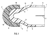
- Figur 1 eine Ausführungsform eines Treibspiegels der Patrone im Schnitt;
- Figur 2 eine komplette Patrone zum Austreiben von Flüssigkeiten unter Druck in einem Waffenrohr im Schnitt.
- In die Patrone 1 zum Austreiben von Flüssigkeiten, insbesondere von Wasser, unter Druck ist als Trennvorrichtung zwischen einer Treibladungskammer 2 und einer Flüssigkeitskammer 3 ein Treibspiegel 4 eingesetzt.
- Der Treibspiegel 4 besteht aus einem Antriebskörper 5 aus einem Kunststoff, beispielsweise einem Polyamid, und dem am Kopf des Antriebskörpers 5 axial angeordneten Abschlußelement 6. Der Antriebskörper 5 des Treibspiegels 4 ist im wesentlichen als hohlzylindrischer Körper ausgebildet, dessen hintere offene Stirnfläche 7 zur Treibladungskammer 2 gerichtet ist. Die äußere Mantelfläche besitzt in diesem hinteren Bereich eine umlaufende Rille 8 zur Transportbefestigung mit der Patronenhülse 13. Im vorderen Bereich ist der Antriebskörper 5 mit einer stirnseitigen Einziehung 9 ausgebildet, die in einer kugeligen oder kugelähnlichen Form 10 mit einem zylindrischen Führungsansatz einstückig endet. Der Durchmesser des Führungssatzes entspricht dem nicht dargestellten, verringerten Innendurchmesser des Rohres im Mündungsbereich. Auf diese kugelige Stirnfläche 10 ist das Abschlußelement 6 aus einem Polyurethan-Schaum aufgesteckt.
- Im rückwärtigen Bereich sind in den Mantel umfangsverteilte Schlitze 11 vorgesehen, die eine radiale Bewegung der endseitigen Mantelfläche zulassen. Die Mantelfläche 16 des Antriebskörpers 5 liegt unter leichter Vorspannung an der Innenmantelfläche 14 des Waffenlaufes 15 an.
- Wie aus Figur 2 hervorgeht, besteht die gesamte Patrone aus dem Treibspiegel 4, der in die Patronenhülse 13 eingesetzt ist. In der Patronenhülse 13 befindet sich zum rückwärtigen Ende hin die Treibladungskammer 2 mit der notwendigen Treibladung 27. Den Abschluß in der Patronenhülse bildet das Anzündelement 28. Auf die vordere Stirnfläche 17 des Treibspiegels 4 ist in der geschilderten Weise ein Abschlußelement 6 kraftschlüssig aufgesteckt. Die gesamte Patrone 1 befindet sich in dem Patronenlager 29 des Waffengehäuses 30 mit dem hier nicht gezeichneten Verschluß. Das Waffenrohr 24 ist in dem Waffengehäuse 30 in nicht mehr gezeigter Darstellung arretiert. An die im wesentlichen radiale Zulauföffnung 26 ist im Waffenrohr 24 ein Rückschlagventil 31 angeordnet, welches mit einer Hydraulikpumpe 32 durch eine Rohrleitung 33 verbunden ist. Eine weitere Rohrleitung 34 befindet sich zwischen einem Flüssigkeitsbehälter 35 und der Hydraulikpumpe 32.
- Der Treibspiegel 4 erlaubt somit das getrennte Zuführen und Laden der Antriebskomponenten, nämlich der Patronenhülse 13 mit der Anzündung 28, der Pulvertreibladung 27, dem Antriebskörper 5 und dem vorderen Abschlußelement 6 und der anzutreibenden Flüssigkeit, beispielsweise Wasser, aus dem Behälter 35 bis zur Flüssigkeitskammer 3.
- Die Antriebskomponenten werden vom Verschluß oder einer entsprechenden Zuführvorrichtung in das Patronenlager 29 des Waffenrohres 24 eingeführt. Das Patronenlager 29 wird durch den hier nicht gezeichneten Verschluß rückseitig verschlossen und verriegelt. Die abzuschließende Flüssigkeitsmenge wird durch die Zulauföffnung 26 des Waffenrohres 24 unter Zwischenschaltung eines Rückschlagventiles 31 von einer Hydraulikpumpe 32 in die ringförmige Kammer 3 zwischen dem Abschlußelement 6 und dem Antriebskörper 5 des Treibspiegels 4 eingepumpt. Durch den auftretenden Flüssigkeitsdruck findet eine axiale Trennung des Abschlußelementes 6 vom Antriebskörper 5 statt. Durch die unter Druck nachströmende Flüssigkeit wird das Abschlußelement 6 in dem Waffenlauf 15 unter Überwindung der äußeren Reibkraft nach vorne in Richtung zur Waffenrohrmündung geschoben. Dabei liegt der zylindrische Teil 18 des Abschlußelementes 6 dichtend und unter leichtem Druck an der Innenmantelfläche 14 des Waffenlaufes 15 an. Wird nun die Flüssigkeitszufuhr beendet, so steht kein Druck mehr für das Verschieben des Abschlußelementes 6 zur Verfügung. Das Abschlußelement 6 bleibt stehen und bildet somit die vordere Abdichtung der Flüssigkeit im Waffenrohr 24. Der Antriebskörper 5 wurde bei der Flüssigkeitszufuhr durch die Patronenhülse 13 an seinem Ort gehalten und bildet dadurch die hintere Abdichtung für die Flüssigkeit.
- Nach diesem erfolgten Zuführvorgang der Flüssigkeit ist die Patrone schußbereit. Bei Zündung der Patrone 1 entsteht in dem Innenraum 19 des Antriebskörpers 5 ein Gasdruck, der sich entsprechend der Pfeile 20 radial gegen die Innenwandung 21 des Antriebskörpers anlegt. Der Antriebskörper 5 des Treibspiegels 4 wird dadurch in Richtung zur Waffenrohrmündung getrieben und schiebt bei dieser Bewegung die Flüssigkeitssäule vor dem Treibspiegel 4 gegen das Abschlußelement 6, welches aus dem Waffenrohr 24 herausgedrückt wird. Durch den Gasdruck 20 liegt gleichzeitig das sich radial und federnd aufweitbare mittlere und hintere Teilstück des Antriebskörpers an der Innenwandung 14 des Waffenlaufes 15 dichtend an.
- Das Heraustreiben des Treibspiegels 4 erfolgt mit einer sehr hohen Geschwindigkeit von etwa 1.000 m/s. Das Wasser bzw. die eingegebene Flüssigkeit wird dabei wie ein Geschoß über den Treibspiegel 4 von dem Druck der verbrennenden Treibladung 27 angetrieben. Bei Anwendung dieses sog. Wasserhammers bei einem Streckenvortrieb im Bergbau wird diese Wassersäule mit dem vorderen Abschlußelement 6 in Bohrlöcher des Streckenkerns hineingeschossen. Durch den sehr hohen Druckstoß von mehreren Tausend Bar wird das Gestein innerhalb des Streckenkerns zerkleinert.
Claims (6)
- Patrone (1) zum Austreiben von Flüssigkeiten unter Druck, mit einer Treibladungskammer und einer zwischen der Treibladungskammer (2) und einer Flüssigkeitskammer (3) angeordneten Trennvorrichtung, die als Treibspiegel (4) ausgebildet ist, welcher aus einem Antriebskörper (5) und einem stirnseitig vorgesehenen Abschlußelement (6) besteht, dadurch gekennzeichnet,
daß der Antriebskörper (5) als ein hohlzylindrischer und zur hinteren Treibladungskammer (2) offener Körper aus einem elastisch verformbaren Material mit vorderer stirnseitiger Einziehung (9) ausgebildet ist, die von einem zylindrischen Bereich ausgehend, in einer kugeligen oder kugelähnlichen Form (10) einstückig endet und das elastisch verformbare Abschlußelement (6) aufnimmt. - Patrone nach Anspruch 1,
dadurch gekennzeichnet,
daß das Abschlußelement (6) aus einem Kunststoff gebildet ist. - Patrone nach den Ansprüchen 1 und 2,
dadurch gekennzeichnet,
daß das Abschlußelement (6) aus einem Polyurethan-Schaum gebildet ist. - Patrone nach den Ansprüchen 1 bis 3,
dadurch gekennzeichnet,
daß die Außenmantelfläche (16) des Antriebskörpers (5) zusammen mit dem Abschlußelement (6) im Waffenlauf (15) eine im Volumen vergrößerbare Flüssigkeitskammer (3) bildet, die mit einer im wesentlichen radialen Zulauföffnung im Waffenrohr (24) korrespondiert. - Patrone nach den Ansprüchen 1 bis 4,
dadurch gekennzeichnet,
daß der Antriebskörper (5) von dem Abschlußelement (6) im Waffenlauf (15) durch den Druck der in die Flüssigkeitskammer (3) einströmenden Flüssigkeit axial trennbar ist. - Patrone nach den vorgenannten Ansprüchen,
dadurch gekennzeichnet,
daß der Antriebskörper (5) in seinem hinteren Bereich umfangsverteilt axial laufende Schlitze (11) aufweist.
Priority Applications (1)
| Application Number | Priority Date | Filing Date | Title |
|---|---|---|---|
| AT90114816T ATE83555T1 (de) | 1989-08-07 | 1990-08-02 | Patrone zum austreiben von fluessigkeiten unter druck. |
Applications Claiming Priority (2)
| Application Number | Priority Date | Filing Date | Title |
|---|---|---|---|
| DE3926051A DE3926051A1 (de) | 1989-08-07 | 1989-08-07 | Patrone zum austreiben von fluessigkeiten unter druck |
| DE3926051 | 1989-08-07 |
Publications (2)
| Publication Number | Publication Date |
|---|---|
| EP0412433A1 EP0412433A1 (de) | 1991-02-13 |
| EP0412433B1 true EP0412433B1 (de) | 1992-12-16 |
Family
ID=6386644
Family Applications (1)
| Application Number | Title | Priority Date | Filing Date |
|---|---|---|---|
| EP90114816A Expired - Lifetime EP0412433B1 (de) | 1989-08-07 | 1990-08-02 | Patrone zum Austreiben von Flüssigkeiten unter Druck |
Country Status (6)
| Country | Link |
|---|---|
| US (1) | US5080018A (de) |
| EP (1) | EP0412433B1 (de) |
| JP (1) | JPH0372193A (de) |
| AT (1) | ATE83555T1 (de) |
| DE (2) | DE3926051A1 (de) |
| NO (1) | NO169509C (de) |
Families Citing this family (3)
| Publication number | Priority date | Publication date | Assignee | Title |
|---|---|---|---|---|
| US7845532B2 (en) * | 2006-11-09 | 2010-12-07 | Stanley Fastening Systems, L.P. | Cordless fastener driving device |
| JP2008125937A (ja) * | 2006-11-24 | 2008-06-05 | Shiyoufuu:Kk | 光重合用加圧容器 |
| US9395163B2 (en) * | 2014-01-09 | 2016-07-19 | Randy R. Fritz | Hollow slug and casing |
Family Cites Families (9)
| Publication number | Priority date | Publication date | Assignee | Title |
|---|---|---|---|---|
| US692819A (en) * | 1900-04-21 | 1902-02-11 | David G Knittel | Means for effecting noiseless discharge of guns. |
| US802301A (en) * | 1904-09-28 | 1905-10-17 | Bernard Gasporro | Cartridge. |
| US3313208A (en) * | 1953-03-25 | 1967-04-11 | Jr Edward G Dorsey | Liquid propellant for small caliber gun |
| GB1263522A (en) * | 1969-02-11 | 1972-02-09 | Walter Arthur Foges | Air-gun projectiles |
| US3732821A (en) * | 1971-05-25 | 1973-05-15 | Us Army | Nose ogive for nonlethal projectile |
| US4941390A (en) * | 1980-08-07 | 1990-07-17 | General Electric Company | Liquid propellant gun |
| DE3631249C2 (de) * | 1986-09-13 | 1995-11-09 | Dynamit Nobel Ag | Verfahren zum Zerlegen von Objekten, aus insbesondere Gestein, Beton oder Mauerwerk |
| DE3726490A1 (de) * | 1987-08-08 | 1989-02-16 | Mauser Werke Oberndorf | Patrone zum austreiben von fluessigkeiten unter druck |
| US4779535A (en) * | 1987-10-16 | 1988-10-25 | Nagatoshi Maki | Slug assembly for shotgun shotshell |
-
1989
- 1989-08-07 DE DE3926051A patent/DE3926051A1/de not_active Withdrawn
-
1990
- 1990-06-28 JP JP2171297A patent/JPH0372193A/ja active Pending
- 1990-08-02 DE DE9090114816T patent/DE59000600D1/de not_active Expired - Fee Related
- 1990-08-02 EP EP90114816A patent/EP0412433B1/de not_active Expired - Lifetime
- 1990-08-02 AT AT90114816T patent/ATE83555T1/de not_active IP Right Cessation
- 1990-08-02 NO NO903403A patent/NO169509C/no unknown
- 1990-08-07 US US07/564,040 patent/US5080018A/en not_active Expired - Fee Related
Also Published As
| Publication number | Publication date |
|---|---|
| DE3926051A1 (de) | 1991-02-14 |
| NO169509B (no) | 1992-03-23 |
| NO903403L (no) | 1991-02-08 |
| ATE83555T1 (de) | 1993-01-15 |
| DE59000600D1 (de) | 1993-01-28 |
| US5080018A (en) | 1992-01-14 |
| NO169509C (no) | 1992-07-01 |
| NO903403D0 (no) | 1990-08-02 |
| JPH0372193A (ja) | 1991-03-27 |
| EP0412433A1 (de) | 1991-02-13 |
Similar Documents
| Publication | Publication Date | Title |
|---|---|---|
| DE69915427T2 (de) | Munitionskartusche mit ihrer Treibladungskonfiguration | |
| EP3060875B1 (de) | Patrone | |
| DE2630830A1 (de) | Treibspiegelgeschoss | |
| DE69416976T2 (de) | Zerstreubare Gegenmasse für rückstossfreie Waffen | |
| EP0303198B1 (de) | Patrone zum Austreiben von Flüssigkeiten unter Druck | |
| DE4020673C2 (de) | ||
| EP0412433A1 (de) | Patrone zum Austreiben von Flüssigkeiten unter Druck | |
| DE2822624A1 (de) | Uebungspatrone fuer automatische feuerwaffen | |
| DE10157668B4 (de) | Geschoss | |
| DE1216736B (de) | Zerfallgeschoss fuer Manoevermunition | |
| DE1099905B (de) | Manoeverpatrone fuer Maschinenwaffen | |
| EP1617167B1 (de) | Artilleriegeschoss | |
| DE602006000111T2 (de) | Führungsband für Artilleriegeschoss | |
| DE2232866A1 (de) | Loesbare verbindung zwischen geschoss und treibladungshuelse | |
| DE4009050C2 (de) | ||
| DE2851321C1 (de) | Munition für eine mit flüssigem Treibmittel betriebene Feuerwaffe | |
| DE2331158A1 (de) | Geschoss-fuehrungsring | |
| DE3211535C2 (de) | Luftgewehr | |
| EP1052470A2 (de) | Aufsatzvorrichtung für die Gasabnahme einer automatischen Waffe | |
| AT228095B (de) | Geschoß | |
| EP2191222B1 (de) | Geschützrohr zum verschiessen drallstabilisierter geschosse | |
| AT355524B (de) | Patronenkammer fuer ein bolzensetzgeraet | |
| DE102012005743A1 (de) | Leitwerkstabilisiertes Vollkaliber-Übungsgeschoss | |
| EP2828609A1 (de) | Leitwerkstabilisiertes vollkaliber-übungsgeschoss | |
| DE2700699A1 (de) | Einrichtung zur abdichtung zwischen lauf und revolvertrommel an einer schusswaffe |
Legal Events
| Date | Code | Title | Description |
|---|---|---|---|
| PUAI | Public reference made under article 153(3) epc to a published international application that has entered the european phase |
Free format text: ORIGINAL CODE: 0009012 |
|
| AK | Designated contracting states |
Kind code of ref document: A1 Designated state(s): AT CH DE GB IT LI SE |
|
| 17P | Request for examination filed |
Effective date: 19901222 |
|
| 17Q | First examination report despatched |
Effective date: 19920511 |
|
| GRAA | (expected) grant |
Free format text: ORIGINAL CODE: 0009210 |
|
| AK | Designated contracting states |
Kind code of ref document: B1 Designated state(s): AT CH DE GB IT LI SE |
|
| REF | Corresponds to: |
Ref document number: 83555 Country of ref document: AT Date of ref document: 19930115 Kind code of ref document: T |
|
| REF | Corresponds to: |
Ref document number: 59000600 Country of ref document: DE Date of ref document: 19930128 |
|
| ITF | It: translation for a ep patent filed | ||
| GBT | Gb: translation of ep patent filed (gb section 77(6)(a)/1977) |
Effective date: 19930312 |
|
| PG25 | Lapsed in a contracting state [announced via postgrant information from national office to epo] |
Ref country code: AT Effective date: 19930802 |
|
| PG25 | Lapsed in a contracting state [announced via postgrant information from national office to epo] |
Ref country code: SE Effective date: 19930803 |
|
| PG25 | Lapsed in a contracting state [announced via postgrant information from national office to epo] |
Ref country code: LI Effective date: 19930831 Ref country code: CH Effective date: 19930831 |
|
| PLBE | No opposition filed within time limit |
Free format text: ORIGINAL CODE: 0009261 |
|
| STAA | Information on the status of an ep patent application or granted ep patent |
Free format text: STATUS: NO OPPOSITION FILED WITHIN TIME LIMIT |
|
| 26N | No opposition filed | ||
| REG | Reference to a national code |
Ref country code: CH Ref legal event code: PL |
|
| PG25 | Lapsed in a contracting state [announced via postgrant information from national office to epo] |
Ref country code: GB Effective date: 19940802 |
|
| EUG | Se: european patent has lapsed |
Ref document number: 90114816.3 Effective date: 19940310 |
|
| PG25 | Lapsed in a contracting state [announced via postgrant information from national office to epo] |
Ref country code: DE Effective date: 19950201 |
|
| GBPC | Gb: european patent ceased through non-payment of renewal fee |
Effective date: 19940802 |
|
| PG25 | Lapsed in a contracting state [announced via postgrant information from national office to epo] |
Ref country code: IT Free format text: LAPSE BECAUSE OF NON-PAYMENT OF DUE FEES;WARNING: LAPSES OF ITALIAN PATENTS WITH EFFECTIVE DATE BEFORE 2007 MAY HAVE OCCURRED AT ANY TIME BEFORE 2007. THE CORRECT EFFECTIVE DATE MAY BE DIFFERENT FROM THE ONE RECORDED. Effective date: 20050802 |