EP0412439A2 - Meuleuse et pièce d'écartement adaptable - Google Patents
Meuleuse et pièce d'écartement adaptable Download PDFInfo
- Publication number
- EP0412439A2 EP0412439A2 EP90114854A EP90114854A EP0412439A2 EP 0412439 A2 EP0412439 A2 EP 0412439A2 EP 90114854 A EP90114854 A EP 90114854A EP 90114854 A EP90114854 A EP 90114854A EP 0412439 A2 EP0412439 A2 EP 0412439A2
- Authority
- EP
- European Patent Office
- Prior art keywords
- spacer assembly
- pin
- grinding disc
- drive shaft
- spacer
- Prior art date
- Legal status (The legal status is an assumption and is not a legal conclusion. Google has not performed a legal analysis and makes no representation as to the accuracy of the status listed.)
- Withdrawn
Links
Images

Classifications
-
- B—PERFORMING OPERATIONS; TRANSPORTING
- B27—WORKING OR PRESERVING WOOD OR SIMILAR MATERIAL; NAILING OR STAPLING MACHINES IN GENERAL
- B27B—SAWS FOR WOOD OR SIMILAR MATERIAL; COMPONENTS OR ACCESSORIES THEREFOR
- B27B5/00—Sawing machines working with circular or cylindrical saw blades; Components or equipment therefor
- B27B5/29—Details; Component parts; Accessories
- B27B5/30—Details; Component parts; Accessories for mounting or securing saw blades or saw spindles
- B27B5/34—Devices for securing a plurality of circular saw blades on a single saw spindle; Equipment for adjusting the mutual distance
-
- B—PERFORMING OPERATIONS; TRANSPORTING
- B24—GRINDING; POLISHING
- B24B—MACHINES, DEVICES, OR PROCESSES FOR GRINDING OR POLISHING; DRESSING OR CONDITIONING OF ABRADING SURFACES; FEEDING OF GRINDING, POLISHING, OR LAPPING AGENTS
- B24B23/00—Portable grinding machines, e.g. hand-guided; Accessories therefor
- B24B23/02—Portable grinding machines, e.g. hand-guided; Accessories therefor with rotating grinding tools; Accessories therefor
-
- B—PERFORMING OPERATIONS; TRANSPORTING
- B24—GRINDING; POLISHING
- B24B—MACHINES, DEVICES, OR PROCESSES FOR GRINDING OR POLISHING; DRESSING OR CONDITIONING OF ABRADING SURFACES; FEEDING OF GRINDING, POLISHING, OR LAPPING AGENTS
- B24B27/00—Other grinding machines or devices
- B24B27/06—Grinders for cutting-off
- B24B27/08—Grinders for cutting-off being portable
-
- B—PERFORMING OPERATIONS; TRANSPORTING
- B24—GRINDING; POLISHING
- B24B—MACHINES, DEVICES, OR PROCESSES FOR GRINDING OR POLISHING; DRESSING OR CONDITIONING OF ABRADING SURFACES; FEEDING OF GRINDING, POLISHING, OR LAPPING AGENTS
- B24B45/00—Means for securing grinding wheels on rotary arbors
-
- B—PERFORMING OPERATIONS; TRANSPORTING
- B28—WORKING CEMENT, CLAY, OR STONE
- B28D—WORKING STONE OR STONE-LIKE MATERIALS
- B28D1/00—Working stone or stone-like materials, e.g. brick, concrete or glass, not provided for elsewhere; Machines, devices, tools therefor
- B28D1/02—Working stone or stone-like materials, e.g. brick, concrete or glass, not provided for elsewhere; Machines, devices, tools therefor by sawing
- B28D1/04—Working stone or stone-like materials, e.g. brick, concrete or glass, not provided for elsewhere; Machines, devices, tools therefor by sawing with circular or cylindrical saw-blades or saw-discs
- B28D1/048—Working stone or stone-like materials, e.g. brick, concrete or glass, not provided for elsewhere; Machines, devices, tools therefor by sawing with circular or cylindrical saw-blades or saw-discs with a plurality of saw blades
-
- Y—GENERAL TAGGING OF NEW TECHNOLOGICAL DEVELOPMENTS; GENERAL TAGGING OF CROSS-SECTIONAL TECHNOLOGIES SPANNING OVER SEVERAL SECTIONS OF THE IPC; TECHNICAL SUBJECTS COVERED BY FORMER USPC CROSS-REFERENCE ART COLLECTIONS [XRACs] AND DIGESTS
- Y10—TECHNICAL SUBJECTS COVERED BY FORMER USPC
- Y10T—TECHNICAL SUBJECTS COVERED BY FORMER US CLASSIFICATION
- Y10T279/00—Chucks or sockets
- Y10T279/16—Longitudinal screw clamp
-
- Y—GENERAL TAGGING OF NEW TECHNOLOGICAL DEVELOPMENTS; GENERAL TAGGING OF CROSS-SECTIONAL TECHNOLOGIES SPANNING OVER SEVERAL SECTIONS OF THE IPC; TECHNICAL SUBJECTS COVERED BY FORMER USPC CROSS-REFERENCE ART COLLECTIONS [XRACs] AND DIGESTS
- Y10—TECHNICAL SUBJECTS COVERED BY FORMER USPC
- Y10T—TECHNICAL SUBJECTS COVERED BY FORMER US CLASSIFICATION
- Y10T279/00—Chucks or sockets
- Y10T279/34—Accessory or component
- Y10T279/3406—Adapter
- Y10T279/3418—Adapter for particular tool or workpiece
Definitions
- the present invention relates to a grinding tool, and particularly to one provided with two spaced grinding discs for simultaneously cutting two spaced grooves.
- the invention also relates to a spacer assembly which may be used with existing grinding tools having but a single grinding disc, to convert the grinding tool to one capable of simultaneously cutting two spaced grooves.
- the invention is particularly useful with respect to grinding tools for cutting grooves in concrete walls in order to accommodate pipes or conduits passing through the walls.
- the grinding tool When the grinding tool is used for this purpose, it cuts two spaced grooves in the concrete wall, and the space between the grooves is then chiselled out in order to define a larger groove for accommodating the pipe or conduit.
- One known form of grinding tool used for this purpose includes a grinding disc which cuts a single groove at one time.
- the two grooves must be cut separately, which substantially increases the time required for performing this operation.
- Another type of grinding tool is also known including two grinding discs in spaced relation and adapted to simultaneously cut two spaced grooves, but such a known tool is substantially more complicated in construction, and therefore more expensive, than the single-disc grinding tool mentioned above.
- An object of the present invention is to provide a grinding tool of relatively simple construction adapted to simultaneously cut two spaced grooves.
- Another object of the invention is to provide a spacer assembly which may be used with the existing single-disc grinding tools to convert such a tool for simultaneously cutting two spaced grooves.
- a grinding tool comprising a rotary motor driving a rotary drive shaft; a first grinding disc having a center opening for receiving said drive shaft with the outer end of the drive shaft projecting through the opening in the grinding disc; a spacer assembly having a socket at one end receiving the projecting end of said drive shaft, a pin at the opposite end, and spacer means between said socket and pin; a second grinding disc having a center opening for receiving said pin of the spacer assembly with the outer end of the pin projecting through the latter opening; and an outer collar attached to said projecting end of the pin for securing the two grinding discs to the drive shaft in spaced apart relationship such as to enable the grinding tool to cut two spaced grooves.
- a spacer assembly for use with a grinding tool comprising: a rotary motor driving a rotary drive shaft, a first grinding disc having a center opening for receiving the drive shaft with the outer end of the drive shaft projecting through the opening in the grinding disc, and an outer collar attached to the projecting end of the pin for securing the grinding disc to the drive shaft.
- the spacer assembly comprises a socket at one end receiving the projecting end of the drive shaft, a pin at the opposite end, and spacer means between the socket and pin.
- the pin is adapted to project through the opening of the first grinding disc to thereby enable the spacer assembly to receive a second grinding disc having a center opening receiving the pin with the outer end of the pin projecting through the latter opening, whereby the outer collar may be attached to the projecting end of the pin to secure the two grinding discs to the drive shaft in spaced apart relation, and thereby to enable the grinding tool to simultaneously cut two spaced grooves.
- the spacer assembly comprises a first spacer washer fixed at the socket end of the spacer assembly to bear against the first grinding disc; and a second spacer washer fixed at the pin end of the spacer assembly to bear against the second grinding disc.
- the spacer assembly may further comprise one or more additional washers received over the pin between the second washer and the second grinding disc, to further space the second grinding disc from the first grinding disc.
- the invention may be embodied in either a grinding tool constructed to have two grinding discs, or in a spacer assembly for converting existing single-disc grinding tools to two disc grinding tools, to enable two grooves to be simultaneously cut.
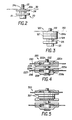
- Fig. 1 illustrates a known grinding tool commonly used for cutting a single groove but modified to include a spacer assembly constructed in accordance with the present invention to convert the grinding tool to one for simultaneously cutting two spaced grooves.
- such grinding tools are commonly used for cutting grooves in concrete to support pipes or other conduits, by cutting two spaced grooves and then chiselling out the concrete between the grooves to provide an enlarged groove for accommodating the pipe or other conduits.
- the grinding tool illustrated in Fig. 1 includes a rotary motor 2 within a housing and having a rotary drive shaft 4 projecting through one end of the motor housing.
- Drive shaft 4 is externally threaded and is adapted to receive a grinding disc 6 formed with a central opening 6a through which drive shaft 4 projects.
- the grinding disc is securely fixed to the drive shaft 4 by an inner collar 8 and an outer collar 10. Both collars are formed with central openings 8a, 10a, which are internally threaded for receiving the externally-threaded drive shaft 4 of the motor 2.
- the outer collar 10 is further formed with a pair of recesses 1Ob for receiving a tool to tighten the outer collar 10 onto drive shaft 4.
- the drive shaft 4 is further provided with a head 4a of polygonal (e..g, hexagonal) configuration for receiving a wrench in order to apply the counter-force when the outer collar 10 is threaded onto the drive shaft 4 to clamp the grinding disc 6 between it and the inner collar 8.
- the grinding tool illustrated in Fig. 1 further includes a side-handle 12 to facilitate holding the tool when used for cutting grooves.
- Grinding disc usually a carborundum disc including a metal insert 6b engaged by the two collars 8, 10 for firmly fixing the disc to the drive shaft 4.
- the single-disc grinding tool illustrated in Fig. 1 includes a spacer assembly, generally designated 20, to enable a second grinding disc 30 to be secured to the drive shaft 4 in spaced relationship with respect to the first grinding disc 6, and thus to enable the grinding tool to simultaneously cut two spaced grooves, instead of a single groove as in the conventional single-disc grinding tool.
- the spacer assembly 20 is formed with a bore or socket 21 at one end for receiving the projecting end of the drive shaft 4, a pin 22 at the opposite end for receiving the outer collar 10, two spacer discs 23, 24, and a hexagonal head 25 between the two spacer discs.
- Spacer assembly 20 is preferably constructed as a single unit in which all the foregoing elements are integrally fixed to each other.
- Socket 21 formed at one end of the spacer assembly 20 is internally threaded so as to mate with the externally-threaded drive shaft 14 projecting through the opening 6a in grinding disc 6.
- Pin 22 at the opposite end is externally threaded so as to mate with the internal threads of the outer collar 10 when pin 22 is passed through the central opening 30a of the second grinding disc 30.
- the second grinding disc 30 is also provided with a metal insert 30b which is engaged between washer 24 and the outer collar 20 when the latter is applied, to firmly secure the grinding disc to the drive shaft 4 in spaced relationship with respect to the first grinding disc 6.
- the outer spacer washer 24, adapted to bear against the outer grinding disc 30, is formed with a circular rib 24a adapted to project through the center opening 30a of grinding disc 30 to engage the inner edge of its metal insert 30b.
- circular rib 24a is slightly thicker than the thickness of grinding disc 30 and its metal insert 30b so as to project slightly on the opposite side of the grinding disc. It is received within a circular recess (not shown) formed in the underface of the outer collar 10 circumscribing its opening 1Oa. Such an arrangement firmly clamps the outer grinding disc 30 between spacer washer 24 of spacer assembly 20 and the outer collar 10.
- the first grinding disc 6 is applied in the conventional manner except that the spacer assembly 20 is used, instead of the outer collar 10, for clamping it to drive shaft 4, the tightening of the spacer assembly 20 onto the drive shaft 4 being effected by a wrench received by the hexagonal head 4a of the drive shaft and 25 of the spacer assembly.
- the second disc 30 is clamped between spacer assembly 20 and the outer collar 10, the threading of the outer collar onto pin 22 being 1o outer collar (10, Fig. 1) to the pin 122 of the spacer assembly, with the two grinding discs spaced apart by the spacer assembly.
- Fig. 4 illustrates a spacer assembly, generally designated 220, which is similar to spacer assembly 20 in Figs. 1 and 2, except that the outer spacer washer 224 is not formed with an annular rib (24a, Figs. 1 and 2), but rather with an annular recess 224a circumscribing its pin 222.
- the outer collar 220 is also formed with an annular recess 220c (as described above with respect to Figs. 1 and 2) circumscribing its opening 220a for receiving pin 22.
- the outer disc 230 is firmly clamped between the outer non-recessed surfaces of spacer washer 224 and the outer collar 220.
- a similar construction is provided with respect to the inner spacer washer 223 of spacer assembly 220 and the inner collar 208.
- both are formed with circular recesses, as shown at 208a and 223a, respectively, for firmly clamping the inner grinding disc 206 to the motor drive shaft 4.
- Fig. 5 illustrates a spacer assembly, generally designated 320, similar to that of Fig. 4 but adapted to accommodate a plurality of further spacer washers, 326, in order to increase the spacing between the two grindings discs 206 and 330. Otherwise, the construction of the spacer assembly 230 is basically the same as described above with respect to Fig. 4.
- the invention permits single-disc grinding tools to be easily converted to two-disc tools wherein two grooves are simultaneously cut.
- Any or all of the above-described spacer assemblies may be provided to enable the user not only to quickly convert the single-disc tool for simultaneously cutting two grooves, but also to space the grooves as may be desired for any particular application.
- either of the spacer assemblies illustrated in Figs. 2 and 4 may be used; and if the grooves are to be cut are to accommodate a one-inch pipe, either of the spacer assemblies illustrated in Figs. 3 and 5 may be used.
- the spacing may be further varied by increasing or decreasing the number of spacer washers (e.g., 127, 327) included in the spacer assembly.
Landscapes
- Engineering & Computer Science (AREA)
- Mechanical Engineering (AREA)
- Life Sciences & Earth Sciences (AREA)
- Wood Science & Technology (AREA)
- Forests & Forestry (AREA)
- Mining & Mineral Resources (AREA)
- Polishing Bodies And Polishing Tools (AREA)
- Finish Polishing, Edge Sharpening, And Grinding By Specific Grinding Devices (AREA)
- Constituent Portions Of Griding Lathes, Driving, Sensing And Control (AREA)
Applications Claiming Priority (2)
| Application Number | Priority Date | Filing Date | Title |
|---|---|---|---|
| IL91283 | 1989-08-11 | ||
| IL91283A IL91283A0 (en) | 1989-08-11 | 1989-08-11 | Grinding tool and spacer assembly for use therein |
Publications (2)
| Publication Number | Publication Date |
|---|---|
| EP0412439A2 true EP0412439A2 (fr) | 1991-02-13 |
| EP0412439A3 EP0412439A3 (en) | 1991-06-12 |
Family
ID=11060276
Family Applications (1)
| Application Number | Title | Priority Date | Filing Date |
|---|---|---|---|
| EP19900114854 Withdrawn EP0412439A3 (en) | 1989-08-11 | 1990-08-02 | Grinding tool and spacer assembly for use therein |
Country Status (4)
| Country | Link |
|---|---|
| US (1) | US5020280A (fr) |
| EP (1) | EP0412439A3 (fr) |
| JP (1) | JPH03131468A (fr) |
| IL (1) | IL91283A0 (fr) |
Cited By (5)
| Publication number | Priority date | Publication date | Assignee | Title |
|---|---|---|---|---|
| EP0896861A3 (fr) * | 1997-08-11 | 2000-11-15 | T:mi Vaunutuote Tanttu | Outil combiné de meulage et de tronçonnage |
| US7722444B2 (en) | 2005-05-13 | 2010-05-25 | Black & Decker Inc. | Angle grinder |
| CN101797775A (zh) * | 2010-04-13 | 2010-08-11 | 厉保永 | 石材切边机 |
| EP2497616A1 (fr) * | 2011-03-10 | 2012-09-12 | Black & Decker Inc. | Outil électrique oscillant |
| US10818450B2 (en) | 2017-06-14 | 2020-10-27 | Black & Decker Inc. | Paddle switch |
Families Citing this family (33)
| Publication number | Priority date | Publication date | Assignee | Title |
|---|---|---|---|---|
| JPH0768464A (ja) * | 1993-09-03 | 1995-03-14 | Hitachi Koki Co Ltd | 固定側フランジ |
| JP3333627B2 (ja) * | 1994-04-06 | 2002-10-15 | 株式会社マキタ | 回転研削工具のツール固止装置 |
| USD376968S (en) | 1995-02-28 | 1996-12-31 | Lg Industrial Systems Co., Ltd. | Grinder |
| US6042461A (en) * | 1998-11-10 | 2000-03-28 | Matweld, Inc. | Mounting assembly |
| US6264408B1 (en) * | 2000-02-17 | 2001-07-24 | Hui Ping Lung | Pneumatic tool kit |
| IT249488Y1 (it) * | 2000-03-28 | 2003-05-19 | Gommaplastica Di Giordana R & | Dispositivo portatile di taglio a lama regolabile in altezza per l'esecuzione di tagli paralleli ad un piano di riferimento, particolarmente |
| US6572455B1 (en) * | 2000-07-13 | 2003-06-03 | Zimmer, Inc. | Method and apparatus for deburring machined workpieces |
| SE521638C2 (sv) * | 2001-04-23 | 2003-11-18 | Globe Invent Ab | Metod för bearbetning av ett objekt, maskin och verktygsenhet för utförande av metoden |
| US6783431B2 (en) | 2002-03-06 | 2004-08-31 | Michael Girten | Joint forming tool and method |
| US6769423B1 (en) * | 2002-06-27 | 2004-08-03 | Charlie Zhang | Sandwich tuck pointing blade |
| US6929000B2 (en) * | 2002-07-08 | 2005-08-16 | Micron Technology, Inc. | Apparatus and methods for aligning a center of mass with a rotational axis of a shaft or spindle |
| DE10257687B4 (de) * | 2002-12-10 | 2006-03-23 | Peter Klotz | Polierball |
| JP2005219155A (ja) * | 2004-02-05 | 2005-08-18 | Sankyo Diamond Industrial Co Ltd | 溝切り用研削工具 |
| US8413645B2 (en) * | 2005-03-23 | 2013-04-09 | Husqvarna Ab | Cutting or sawing machine |
| US7143759B1 (en) * | 2006-05-22 | 2006-12-05 | Fu-Chun Wang | Slotter provided with simultaneously two-way rotary saw blades |
| DE102007007787A1 (de) * | 2007-02-16 | 2008-08-21 | Robert Bosch Gmbh | Schleifteller für eine Exzenterschleifmaschine |
| US8747190B2 (en) * | 2010-04-08 | 2014-06-10 | Mark Smith | Tool for removing grout, mortar and the like |
| US20110266759A1 (en) * | 2010-04-29 | 2011-11-03 | Black & Decker Inc. | Oscillating tool |
| CN201931158U (zh) * | 2010-11-30 | 2011-08-17 | 宁波黑松工具有限公司 | 双锯片切割机 |
| WO2013029063A1 (fr) * | 2011-07-19 | 2013-02-28 | Morrison Brett Michael | Meuleuse d'angle améliorée |
| WO2015035499A1 (fr) * | 2013-09-10 | 2015-03-19 | Pykari Dave | Scie à échantillons à canaux et élément d'espacement |
| DE102013110009B3 (de) * | 2013-09-12 | 2015-02-05 | Rhodius Schleifwerkzeuge Gmbh & Co. Kg | Schneidwerkzeug |
| US9475172B2 (en) | 2014-07-15 | 2016-10-25 | Milwaukee Electric Tool Corporation | Adjustable guard for power tool |
| AU2016326632B2 (en) * | 2015-09-24 | 2020-02-06 | Husqvarna Ab | Polishing or grinding pad assembly |
| USD854902S1 (en) | 2016-09-23 | 2019-07-30 | Husqvarna Construction Products North America, Inc. | Polishing or grinding pad |
| CN108995048B (zh) * | 2016-12-30 | 2020-02-21 | 泉州市佳能机械制造有限公司 | 回转体石材加工一体机 |
| USD958626S1 (en) | 2017-08-30 | 2022-07-26 | Husqvarna Ab | Polishing or grinding pad assembly with abrasive disks, reinforcement and pad |
| AU201810919S (en) | 2017-08-30 | 2018-04-13 | Husqvarna Construction Products North America | Polishing or grinding pad assembly with abrasive discs reinforcement and pad |
| USD927952S1 (en) | 2017-08-30 | 2021-08-17 | Husqvarna Ab | Polishing or grinding pad assembly with abrasive disk, spacer, reinforcement and pad |
| US10710214B2 (en) | 2018-01-11 | 2020-07-14 | Husqvarna Ab | Polishing or grinding pad with multilayer reinforcement |
| US12226925B2 (en) | 2020-02-04 | 2025-02-18 | Baron Investments, Llc | Spacers for cutting and grinding blades, blade and spacer assemblies, and gang blade assemblies and methods relating to same |
| CN111844270B (zh) * | 2020-07-27 | 2021-10-26 | 中原工学院 | 一种高效建筑家具木材切割装置 |
| US20220304223A1 (en) * | 2021-03-25 | 2022-09-29 | Coby Tabor | Apparatus and Method for Extending the Output Shaft of a String Trimmer |
Family Cites Families (12)
| Publication number | Priority date | Publication date | Assignee | Title |
|---|---|---|---|---|
| US1883392A (en) * | 1931-04-15 | 1932-10-18 | Moll Edwin | Power driven mechanic's hand tool |
| US1979325A (en) * | 1931-10-01 | 1934-11-06 | Goldberg Herman | Grinding and polishing apparatus |
| GB398519A (en) * | 1932-03-07 | 1933-09-15 | Johansson Ab C E | Apparatus for grinding screw threads |
| US2887830A (en) * | 1957-03-07 | 1959-05-26 | Harry C Else | Grinding apparatus |
| FR1292700A (fr) * | 1961-06-21 | 1962-05-04 | Appareil pour le creusage de saignées dans des murs ou cloisons | |
| US4009637A (en) * | 1974-10-16 | 1977-03-01 | H. Putsch & Comp. | Milling device |
| US4033319A (en) * | 1975-07-25 | 1977-07-05 | Winter Eugene S | Blade guide and slab support for lapidary saw |
| US4188934A (en) * | 1978-10-20 | 1980-02-19 | Cushion Cut, Inc. | Step safety groover apparatus |
| US4236356A (en) * | 1979-01-05 | 1980-12-02 | Ward John D | Cutting saw and concrete groover |
| JPS55120975A (en) * | 1979-12-10 | 1980-09-17 | Nisshin Kikai Seisakusho:Kk | Adjusting device for interval between plural rotating grinders |
| JPS61188074A (ja) * | 1985-02-15 | 1986-08-21 | Canon Inc | 研削装置 |
| JPS62199356A (ja) * | 1986-02-26 | 1987-09-03 | Mitsubishi Metal Corp | 研削盤 |
-
1989
- 1989-08-11 IL IL91283A patent/IL91283A0/xx unknown
-
1990
- 1990-07-31 US US07/560,830 patent/US5020280A/en not_active Expired - Fee Related
- 1990-08-02 EP EP19900114854 patent/EP0412439A3/en not_active Withdrawn
- 1990-08-09 JP JP2211443A patent/JPH03131468A/ja active Pending
Cited By (7)
| Publication number | Priority date | Publication date | Assignee | Title |
|---|---|---|---|---|
| EP0896861A3 (fr) * | 1997-08-11 | 2000-11-15 | T:mi Vaunutuote Tanttu | Outil combiné de meulage et de tronçonnage |
| US7722444B2 (en) | 2005-05-13 | 2010-05-25 | Black & Decker Inc. | Angle grinder |
| US8087976B2 (en) | 2005-05-13 | 2012-01-03 | Black & Decker Inc. | Trigger assembly for angle grinder |
| US8087977B2 (en) | 2005-05-13 | 2012-01-03 | Black & Decker Inc. | Angle grinder |
| CN101797775A (zh) * | 2010-04-13 | 2010-08-11 | 厉保永 | 石材切边机 |
| EP2497616A1 (fr) * | 2011-03-10 | 2012-09-12 | Black & Decker Inc. | Outil électrique oscillant |
| US10818450B2 (en) | 2017-06-14 | 2020-10-27 | Black & Decker Inc. | Paddle switch |
Also Published As
| Publication number | Publication date |
|---|---|
| EP0412439A3 (en) | 1991-06-12 |
| IL91283A0 (en) | 1990-03-19 |
| US5020280A (en) | 1991-06-04 |
| JPH03131468A (ja) | 1991-06-05 |
Similar Documents
| Publication | Publication Date | Title |
|---|---|---|
| US5020280A (en) | Grinding tool and spacer assembly for use therein | |
| US7666070B2 (en) | Tool holder for a disc-shaped working tool | |
| US4325664A (en) | Cutting tool | |
| EP0188354B1 (fr) | Dispositif de serrage manuel pour le maintien d'un outil de coupe | |
| US5902066A (en) | Taper shaft lock | |
| US5609454A (en) | Driving assembly for driving opposed members to move toward and away from each other | |
| US7168900B2 (en) | Total support with a collet chuck receiver | |
| JP2002059351A (ja) | 携帯型ロータリー突切りバイト | |
| JPH09141607A (ja) | ルータコレットアセンブリ | |
| EP0666144B1 (fr) | Dispositif pour le serrage d'une pièce sur un support plan tel que la table d'une machine outil | |
| US4924634A (en) | Finishing article having an integral mounting hub and improved base | |
| EP0543789B1 (fr) | Système de fixation pour une lame de scie circulaire à déligner et un disque-déchiqueteur | |
| JPH0431812B2 (fr) | ||
| CA2485935C (fr) | Dispositif de mandrin pour outils rotatifs | |
| CA2241033C (fr) | Attache combinee ecrou-collerette | |
| US5383383A (en) | Tool mounting means and implement therefor | |
| US4211507A (en) | Rotary cutting tool with radially adjustable, reversible tool bits | |
| JP2004181622A (ja) | ツール収容部構造 | |
| US6799358B2 (en) | Method for assembling and disassembling cutting inserts | |
| EP0138336A1 (fr) | Outil de tournage | |
| US7172377B2 (en) | Router or cutter bit chuck or extension | |
| US6912755B2 (en) | Clamping device of a rotating tool | |
| US6792834B2 (en) | Tool for rotating cutting heads | |
| US20060280569A1 (en) | Hole Saw Arbor System For Power Drill Assisted Tightening And Loosening | |
| JPS6039002A (ja) | 切削チツプ取付装置 |
Legal Events
| Date | Code | Title | Description |
|---|---|---|---|
| PUAI | Public reference made under article 153(3) epc to a published international application that has entered the european phase |
Free format text: ORIGINAL CODE: 0009012 |
|
| AK | Designated contracting states |
Kind code of ref document: A2 Designated state(s): DE ES FR GB IT SE |
|
| PUAL | Search report despatched |
Free format text: ORIGINAL CODE: 0009013 |
|
| AK | Designated contracting states |
Kind code of ref document: A3 Designated state(s): DE ES FR GB IT SE |
|
| STAA | Information on the status of an ep patent application or granted ep patent |
Free format text: STATUS: THE APPLICATION IS DEEMED TO BE WITHDRAWN |
|
| 18D | Application deemed to be withdrawn |
Effective date: 19911213 |