EP0412441A2 - Radar multifonction - Google Patents
Radar multifonction Download PDFInfo
- Publication number
- EP0412441A2 EP0412441A2 EP90114878A EP90114878A EP0412441A2 EP 0412441 A2 EP0412441 A2 EP 0412441A2 EP 90114878 A EP90114878 A EP 90114878A EP 90114878 A EP90114878 A EP 90114878A EP 0412441 A2 EP0412441 A2 EP 0412441A2
- Authority
- EP
- European Patent Office
- Prior art keywords
- radar
- power
- function
- optimal
- lobe
- Prior art date
- Legal status (The legal status is an assumption and is not a legal conclusion. Google has not performed a legal analysis and makes no representation as to the accuracy of the status listed.)
- Granted
Links
Images


Classifications
-
- G—PHYSICS
- G01—MEASURING; TESTING
- G01S—RADIO DIRECTION-FINDING; RADIO NAVIGATION; DETERMINING DISTANCE OR VELOCITY BY USE OF RADIO WAVES; LOCATING OR PRESENCE-DETECTING BY USE OF THE REFLECTION OR RERADIATION OF RADIO WAVES; ANALOGOUS ARRANGEMENTS USING OTHER WAVES
- G01S13/00—Systems using the reflection or reradiation of radio waves, e.g. radar systems; Analogous systems using reflection or reradiation of waves whose nature or wavelength is irrelevant or unspecified
- G01S13/66—Radar-tracking systems; Analogous systems
- G01S13/72—Radar-tracking systems; Analogous systems for two-dimensional [2D] tracking, e.g. combination of angle and range tracking, track-while-scan radar
- G01S13/723—Radar-tracking systems; Analogous systems for two-dimensional [2D] tracking, e.g. combination of angle and range tracking, track-while-scan radar by using numerical data
-
- G—PHYSICS
- G01—MEASURING; TESTING
- G01S—RADIO DIRECTION-FINDING; RADIO NAVIGATION; DETERMINING DISTANCE OR VELOCITY BY USE OF RADIO WAVES; LOCATING OR PRESENCE-DETECTING BY USE OF THE REFLECTION OR RERADIATION OF RADIO WAVES; ANALOGOUS ARRANGEMENTS USING OTHER WAVES
- G01S7/00—Details of systems according to groups G01S13/00, G01S15/00, G01S17/00
- G01S7/02—Details of systems according to groups G01S13/00, G01S15/00, G01S17/00 of systems according to group G01S13/00
- G01S7/28—Details of pulse systems
-
- G—PHYSICS
- G01—MEASURING; TESTING
- G01S—RADIO DIRECTION-FINDING; RADIO NAVIGATION; DETERMINING DISTANCE OR VELOCITY BY USE OF RADIO WAVES; LOCATING OR PRESENCE-DETECTING BY USE OF THE REFLECTION OR RERADIATION OF RADIO WAVES; ANALOGOUS ARRANGEMENTS USING OTHER WAVES
- G01S13/00—Systems using the reflection or reradiation of radio waves, e.g. radar systems; Analogous systems using reflection or reradiation of waves whose nature or wavelength is irrelevant or unspecified
- G01S13/02—Systems using reflection of radio waves, e.g. primary radar systems; Analogous systems
- G01S2013/0236—Special technical features
- G01S2013/0245—Radar with phased array antenna
- G01S2013/0254—Active array antenna
-
- G—PHYSICS
- G01—MEASURING; TESTING
- G01S—RADIO DIRECTION-FINDING; RADIO NAVIGATION; DETERMINING DISTANCE OR VELOCITY BY USE OF RADIO WAVES; LOCATING OR PRESENCE-DETECTING BY USE OF THE REFLECTION OR RERADIATION OF RADIO WAVES; ANALOGOUS ARRANGEMENTS USING OTHER WAVES
- G01S13/00—Systems using the reflection or reradiation of radio waves, e.g. radar systems; Analogous systems using reflection or reradiation of waves whose nature or wavelength is irrelevant or unspecified
- G01S13/02—Systems using reflection of radio waves, e.g. primary radar systems; Analogous systems
- G01S2013/0236—Special technical features
- G01S2013/0272—Multifunction radar
Definitions
- the invention relates to a multifunction radar according to the preamble of patent claim 1.
- a multifunction radar with an electronically phased antenna has a number of tasks to perform.
- the following can be important: the search in different areas, the finding of objects for which there is pre-instruction, the clarification of possible false alarms and, if necessary, the quick initiation of target tracking, the tracking of targets of different categories, passive location (e.g. triangulation and trilateration) and that Detect clutter and shadowing.
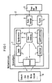
- the multifunction radar fulfills these tasks by the appropriate interaction of its assemblies shown in the figure.
- assemblies that take care of the physical generation of the transmission signals, as well as reception and signal processing, right up to plot formation.
- these are a signal generator 1, a transmitter 2, an electronically phase-controlled antenna 3, a receiver 4 and a received signal processing device 5.
- these modules which e.g. ensures that the phase shifters of the antenna 3 are set correctly, that the transmission and reception frequencies match and that the signal processing is carried out in such a way that it matches the signal being emitted.
- radar control device 6 The assembly that performs this coordination is referred to as radar control device 6. All previously mentioned assemblies are to be summarized under the term radar measuring device 7.
- the radar measuring device 7 defined in this way is capable of executing instructions in which it is determined where (lobe position), how long (illumination duration) and how (signal shape and signal processing form) the multifunction radar should "look". The duration of the lighting is determined by the signal shape.
- Such an instruction which consists of the lobe position, signal form and signal processing form, should be referred to as an elementary radar task.
- the radar measuring device must therefore receive elementary radar orders. It then generates depending on the state of the outside world, i.e. the scenario 8, plots or strobes and delivers them to a multifunction radar target tracking device (tracker) 9, which processes this information.
- the processed information is delivered to a fire control station 10.
- the effort in the construction of the radar measuring device 7 is reflected in the number of executable elementary radar orders.
- a lobe position can be freely selected within a solid angle range.
- the dwell time in this lobe position, the signal form and the signal processing form can also be selected from a wide variety of possibilities. If one also takes into account the fact that in general several hundred such elementary radar orders are to be generated per second, one obtains an idea of the abundance of technical possibilities which the radar measuring device makes available.
- a radar management module 11 should now be understood to mean that module of a multifunction radar which, by skillful use of the radar measuring device 7, ensures that the multifunction radar optimally fulfills all of its tasks indicated above, and that any conflicts of interest that arise are properly resolved.
- the task of the radar management assembly 11 is to at any time cheapest elementary radar order.
- the complexity of radar management results from the vast number of possible combinations of elementary radar orders.
- the best combination is to be selected for each time interval, so that the above-mentioned tasks of the multifunction radar, which is denoted by 12 in the figure, are optimally fulfilled.
- the object of the invention is to treat the generation of the most frequently occurring elementary radar orders as precisely as possible, so that there is a basic framework for radar management. Since the operation under ECM conditions is typical for the use of a multifunction radar, this leads to the special task of the best transmission power distribution in the room as a function of the interference power distribution during the search. The search places the most demands on the radar management, because the most degrees of freedom are available here.
- the quality of transmission power distributions which is dependent on the environment and location, can be described using a utility function. According to the invention, their dynamic optimization then leads to the best search performance distribution and further to the generation of the best elementary radar orders in the search.
- the radar manager In addition to the search, which in typical operation is likely to take up far more than half of the elementary radar orders, the radar manager must take into account all of the previously mentioned tasks of the multifunction radar and generate and plan corresponding elementary radar orders. The planning of the non-search orders is not dealt with here.
- the aim of the search activities of a radar is to detect objects that fly into the space to be monitored as early as possible. This is usually said as follows:
- the range should be as high as possible.
- range terms which must be clearly differentiated, especially if the sampling period is freely selectable. It points out their dependence on the generally unknown and very wide-ranging properties of the objects to be discovered.
- a range term, the monitoring range, which is suitable for the optimization of the radar management is selected.
- the invention also contains optimization information in the case of shadowing or clutter. Since the exact solution to this optimization task contains the optimal signal form selection in detail, no general solution can be given.
- the "clear range” says nothing about the probability of detection of concrete objects.
- the "cumulative detection range" is also unsuitable because it is difficult to handle analytically, but it also assumes that the sampling period is planned ahead over several samples. However, this requirement cannot be met in highly dynamic scenarios (including switching on / off interferers) if the radar should adapt to the situation as quickly as possible and consequently adapt its sampling period again and again.
- the monitoring range is used as the optimality criterion
- R ü R d - v R. T (1) proposed, where R d is the single detection range, v R the radial speed of the "object to be discovered” (towards the radar) and T the sampling period. That v R and R d depend on the behavior and the properties of the "object to be discovered” already shows that the procedure is "Bayesian". This means that the optimization is based on an a priori assumption about the environment that the radar is likely to encounter.
- R d depends on the environmental influences (ECM, clutter), on the fixed radar parameters, on the variable radar parameters (signal form) and the desired detection probability p D (eg 95%).
- ECM environmental influences
- p D variable radar parameters
- Monitoring range is that range R ü, can be guaranteed for the p at the assumed "to be detected objects", and the environmental conditions adopted with probability D, that a radially einfcedes with velocity v R object at a distance R ⁇ R e is detected.
- the invention shows how the optimization of the monitoring range in a lobe position provides the optimal values for monitoring range, signal shape and sampling period for this lobe position as a function of the available power component.
- Equation (6) provides the optimized monitoring range as a function of the power share; equation (5) indicates the associated optimal sampling period.
- T B is the only parameter in (2).
- a pulse would be optimal if you optimize the clear range as a secondary criterion.
- Equation (2) for the single detection range as a function of the signal shape is only approximately correct. If you want to take shading and clutter into account, you have to generalize this equation.
- the signal form is only received via the illumination time T B.
- the unique range is larger (but only slightly larger) than R o . This consideration applies to the case P> P o . Otherwise, the statements made in connection with the explanation of the basic case about the waveform selection remain valid.
- the monitoring range R u , the signal form and signal processing form and the sampling period are obtained as a function of the power component P of a lobe.
- search performance is first operationalized, namely by means of a utility function.
- This utility function is then optimized under the constraint of a limited amount of power available. This optimization takes place on the one hand if there is no clutter and no shading in all clubs involved, whereby borderline cases are also discussed which correspond to the requirement for a uniform monitoring range on the one hand and a fixed power distribution on the other hand. On the other hand, there is an optimization for the general case, i.e. also for cases with club positions in which clutter and shadowing are present. This leads to a method for generating search requests. This method optimizes a utility function defined below, but at the same time realizes a dynamic adaptation to changes in time and external influences.
- a phased array radar opens up the possibility of making the coverage area very flexible, whereby the question arises which of the realizable coverage areas is optimal.
- the answer to this question is one step closer if it is possible to decide whether each of the two coverage areas is "equally good” or which of the two coverage areas is “better”. Then you can define a utility function on the set of coverage areas, their optimization then leads to the "optimal" realizable coverage area.
- a coverage area A is "better" than a second B if the monitoring range in A is greater in every solid angle element than in B.
- the utility function must be a monotonically increasing function of the monitoring ranges in all lobe positions: u (R1, R2, ..., R n ) ⁇ u (R′1, R′2, ..., R ′ n ) (20) if R1 ⁇ R′1, R2 ⁇ R′2, ..., R n ⁇ R ′ n , where n is the number of lobe positions, and R i (or R ′ i ) is the monitoring range in the i-th lobe.
- the c i will normally not differ from lobe position to lobe position, but will have a uniform value in solid angle areas with a uniform threat situation.
- Equation (6) was derived for the monitoring range for the so-called basic case, which is not repeated here.
- the power component p i is proportional to the interference power N i . This means that because of (15) there is the same monitoring range in each club. It also follows that the sampling period is also uniform for all clubs.
- Equation (37) has exactly one solution for each ⁇ > ⁇ min .
- this procedure leads directly to a practicable procedure for parameters that change over time, i.e. it can be used for dynamic optimization.
- this method thus corrects both the power component of the affected club position and ⁇ in such a way that both (37) and (38) "approximately in the longer term" are fulfilled.
- the advantage of the iterative approach presented compared to trying to plan the p i exactly for a long time is the better ability to react to a changing environment.
- the search task can be solved through online planning.
- each lobe position can either not be illuminated at all or at any time. In this case, apart from initialization problems, which will be dealt with later, the time organization is very simple.
- the easiest way to do this is to provide an initialization set that e.g. ensures that the low elevations are scanned first, whereby all azimuth values are equal.
- the optimization of the waveform selection in clutter requires at least information about whether clutter is in the relevant lobe position or not.
- other parameters are required for better optimization, e.g. an assumption about the clutter type (volume or ground clutter), an estimate of the clutter density (in extreme cases as a function of the distance), an estimate of the distance range in which the clutter occurs, and an estimate of the (radial) speed of the clutter and its scatter Speed.
Landscapes
- Engineering & Computer Science (AREA)
- Radar, Positioning & Navigation (AREA)
- Remote Sensing (AREA)
- Computer Networks & Wireless Communication (AREA)
- Physics & Mathematics (AREA)
- General Physics & Mathematics (AREA)
- Radar Systems Or Details Thereof (AREA)
Applications Claiming Priority (8)
| Application Number | Priority Date | Filing Date | Title |
|---|---|---|---|
| DE3926215 | 1989-08-08 | ||
| DE3926198 | 1989-08-08 | ||
| DE19893926197 DE3926197C2 (de) | 1989-08-08 | 1989-08-08 | Multifunktionsradar |
| DE3926197 | 1989-08-08 | ||
| DE19893926198 DE3926198C2 (de) | 1989-08-08 | 1989-08-08 | Multifunktionsradar |
| DE3926216 | 1989-08-08 | ||
| DE19893926216 DE3926216A1 (de) | 1989-08-08 | 1989-08-08 | Multifunktionsradar |
| DE19893926215 DE3926215C2 (de) | 1989-08-08 | 1989-08-08 | Multifunktionsradar |
Publications (3)
| Publication Number | Publication Date |
|---|---|
| EP0412441A2 true EP0412441A2 (fr) | 1991-02-13 |
| EP0412441A3 EP0412441A3 (en) | 1992-03-11 |
| EP0412441B1 EP0412441B1 (fr) | 1995-01-11 |
Family
ID=27434697
Family Applications (1)
| Application Number | Title | Priority Date | Filing Date |
|---|---|---|---|
| EP90114878A Expired - Lifetime EP0412441B1 (fr) | 1989-08-08 | 1990-08-02 | Radar multifonction |
Country Status (3)
| Country | Link |
|---|---|
| US (1) | US5001490A (fr) |
| EP (1) | EP0412441B1 (fr) |
| DE (1) | DE59008231D1 (fr) |
Families Citing this family (20)
| Publication number | Priority date | Publication date | Assignee | Title |
|---|---|---|---|---|
| AU658412B2 (en) * | 1991-05-24 | 1995-04-13 | Commonwealth Of Australia, The | Optimising radar tasking using backwards scheduling |
| US7739167B2 (en) | 1999-03-05 | 2010-06-15 | Era Systems Corporation | Automated management of airport revenues |
| US7908077B2 (en) * | 2003-06-10 | 2011-03-15 | Itt Manufacturing Enterprises, Inc. | Land use compatibility planning software |
| US7612716B2 (en) | 1999-03-05 | 2009-11-03 | Era Systems Corporation | Correlation of flight track data with other data sources |
| US7570214B2 (en) | 1999-03-05 | 2009-08-04 | Era Systems, Inc. | Method and apparatus for ADS-B validation, active and passive multilateration, and elliptical surviellance |
| US7777675B2 (en) * | 1999-03-05 | 2010-08-17 | Era Systems Corporation | Deployable passive broadband aircraft tracking |
| US7667647B2 (en) * | 1999-03-05 | 2010-02-23 | Era Systems Corporation | Extension of aircraft tracking and positive identification from movement areas into non-movement areas |
| US7782256B2 (en) * | 1999-03-05 | 2010-08-24 | Era Systems Corporation | Enhanced passive coherent location techniques to track and identify UAVs, UCAVs, MAVs, and other objects |
| US8446321B2 (en) | 1999-03-05 | 2013-05-21 | Omnipol A.S. | Deployable intelligence and tracking system for homeland security and search and rescue |
| US20100079342A1 (en) * | 1999-03-05 | 2010-04-01 | Smith Alexander E | Multilateration enhancements for noise and operations management |
| US7889133B2 (en) | 1999-03-05 | 2011-02-15 | Itt Manufacturing Enterprises, Inc. | Multilateration enhancements for noise and operations management |
| US8203486B1 (en) | 1999-03-05 | 2012-06-19 | Omnipol A.S. | Transmitter independent techniques to extend the performance of passive coherent location |
| US6177904B1 (en) * | 1999-03-24 | 2001-01-23 | Raytheon Company | Versatile radar data sampling circuit |
| JP4375064B2 (ja) * | 2004-03-10 | 2009-12-02 | 株式会社デンソー | レーダ装置 |
| US7965227B2 (en) * | 2006-05-08 | 2011-06-21 | Era Systems, Inc. | Aircraft tracking using low cost tagging as a discriminator |
| US9130270B1 (en) | 2008-11-24 | 2015-09-08 | The Boeing Company | Scan alignment system |
| US8279117B2 (en) * | 2008-11-24 | 2012-10-02 | The Boeing Company | Burst optimized tracking algorithm |
| CN103631268B (zh) * | 2013-12-03 | 2017-02-15 | 中国航空无线电电子研究所 | 一种雷达辅助红外传感器的目标探测系统及探测方法 |
| CN105158756B (zh) * | 2015-08-27 | 2017-08-08 | 电子科技大学 | 集中式mimo雷达射频隐身时多目标跟踪波束指向方法 |
| CN107728139B (zh) * | 2017-09-12 | 2020-11-17 | 电子科技大学 | 一种基于多目标跟踪的相控阵雷达组网系统资源管理方法 |
Family Cites Families (1)
| Publication number | Priority date | Publication date | Assignee | Title |
|---|---|---|---|---|
| GB2147761B (en) * | 1983-10-07 | 1987-09-03 | Marconi Co Ltd | Radar apparatus |
-
1990
- 1990-08-02 EP EP90114878A patent/EP0412441B1/fr not_active Expired - Lifetime
- 1990-08-02 DE DE59008231T patent/DE59008231D1/de not_active Expired - Fee Related
- 1990-08-03 US US07/562,683 patent/US5001490A/en not_active Expired - Lifetime
Also Published As
| Publication number | Publication date |
|---|---|
| US5001490A (en) | 1991-03-19 |
| DE59008231D1 (de) | 1995-02-23 |
| EP0412441B1 (fr) | 1995-01-11 |
| EP0412441A3 (en) | 1992-03-11 |
Similar Documents
| Publication | Publication Date | Title |
|---|---|---|
| EP0412441B1 (fr) | Radar multifonction | |
| AT521120B1 (de) | Verfahren und Vorrichtung zum Ermitteln eines Radarquerschnitts, Verfahren zum Trainieren eines Wechselwirkungsmodells sowie Radarzielemulator und Prüfstand | |
| DE69118560T2 (de) | Verfahren zur Behandlung von durch phasengesteuerte Gruppenantennen erzeugten Strahlen und Gerät dafür | |
| EP1380854A2 (fr) | Procédé et système radar de détermination d'angles de direction d'objets radar | |
| EP0406879B1 (fr) | Méthode d'extraction d'erreurs de mouvement d'un porteur transportant un système radar d'imagerie cohérent à partir de données radar brutes et dispositif pour la mise en oeuvre de ce procédé | |
| EP0010568B1 (fr) | Procédé et dispositif pour la camouflage d'un objet métallique, afin d'en éviter le repérage par radiomètre, par adaptation de son rayonnement propre au rayonnement ambiant | |
| DE69606094T2 (de) | Radarverfahren und Vorrichtung, die Ziele in Clutterbereichen mittels der Intensität und der Winkellage der Ziele erfassen | |
| EP3112894A1 (fr) | Procede de classification automatique d'objets radar | |
| DE69304127T2 (de) | Verfahren und Einrichtung zur Entdeckung und Ortung von Objekten auf einem relativ ebenen Boden | |
| DE112021007178T5 (de) | Steuerverfahren für ein lidar und lidar | |
| DE3731036A1 (de) | Radar mit großem Augenblicks-Feldwinkel und hohem Augenblicks-Winkelauflösungsvermögen, insbesondere für ein Flugkörper-Zielsuchgerät | |
| DE102021114753A1 (de) | Robuste Reflexionspunktdetektion | |
| EP3620819B1 (fr) | Détection coordonnée des objets dans un espace aérien | |
| DE3343326A1 (de) | Verfahren und vorrichtung zum verbessern der winkelaufloesung eines monopulsradars | |
| EP0487940B1 (fr) | Radar du type pulsdoppler | |
| EP4445174A1 (fr) | Procédé de relevé d'environnement d'un véhicule automobile | |
| DE3926198C2 (de) | Multifunktionsradar | |
| DE2731485C1 (de) | Verfahren und Vorrichtung zur Stoerverminderung bei einem elektromagnetischen Rueckstrahl-Ortungsgeraet | |
| DE3600827C2 (fr) | ||
| DE2258992A1 (de) | Radargeraet mit ueber einen verteiler miteinander gekoppelten primaerstrahlern | |
| DE69611110T2 (de) | Abfragegerät für ein system zur identifizierung eines objekts mittels funk | |
| DE2106035B2 (de) | Vorrichtung zur Überprüfung der Formübereinstimmung eines elektromagnetisch erzeugten Objektbildes mit einem vorgegebenen Schema | |
| DE3926215C2 (de) | Multifunktionsradar | |
| DE102018114109A1 (de) | Koordiniertes Durchsuchen eines Luftraums | |
| DE112021001664T5 (de) | Erkennungsverarbeitungssystem, erkennungsverarbeitungsvorrichtung und erkennungsverarbeitungsverfahren |
Legal Events
| Date | Code | Title | Description |
|---|---|---|---|
| PUAI | Public reference made under article 153(3) epc to a published international application that has entered the european phase |
Free format text: ORIGINAL CODE: 0009012 |
|
| 17P | Request for examination filed |
Effective date: 19901205 |
|
| AK | Designated contracting states |
Kind code of ref document: A2 Designated state(s): BE DE FR GB IT NL |
|
| PUAL | Search report despatched |
Free format text: ORIGINAL CODE: 0009013 |
|
| AK | Designated contracting states |
Kind code of ref document: A3 Designated state(s): BE DE FR GB IT NL |
|
| 17Q | First examination report despatched |
Effective date: 19940411 |
|
| GRAA | (expected) grant |
Free format text: ORIGINAL CODE: 0009210 |
|
| AK | Designated contracting states |
Kind code of ref document: B1 Designated state(s): BE DE FR GB IT NL |
|
| REF | Corresponds to: |
Ref document number: 59008231 Country of ref document: DE Date of ref document: 19950223 |
|
| ITF | It: translation for a ep patent filed | ||
| GBT | Gb: translation of ep patent filed (gb section 77(6)(a)/1977) |
Effective date: 19950317 |
|
| ET | Fr: translation filed | ||
| PG25 | Lapsed in a contracting state [announced via postgrant information from national office to epo] |
Ref country code: GB Effective date: 19950802 |
|
| PG25 | Lapsed in a contracting state [announced via postgrant information from national office to epo] |
Ref country code: BE Effective date: 19950831 |
|
| PLBE | No opposition filed within time limit |
Free format text: ORIGINAL CODE: 0009261 |
|
| STAA | Information on the status of an ep patent application or granted ep patent |
Free format text: STATUS: NO OPPOSITION FILED WITHIN TIME LIMIT |
|
| 26N | No opposition filed | ||
| BERE | Be: lapsed |
Owner name: SIEMENS A.G. Effective date: 19950831 |
|
| PG25 | Lapsed in a contracting state [announced via postgrant information from national office to epo] |
Ref country code: NL Effective date: 19960301 |
|
| GBPC | Gb: european patent ceased through non-payment of renewal fee |
Effective date: 19950802 |
|
| NLV4 | Nl: lapsed or anulled due to non-payment of the annual fee |
Effective date: 19960301 |
|
| REG | Reference to a national code |
Ref country code: FR Ref legal event code: TP |
|
| PGFP | Annual fee paid to national office [announced via postgrant information from national office to epo] |
Ref country code: DE Payment date: 20040805 Year of fee payment: 15 |
|
| PGFP | Annual fee paid to national office [announced via postgrant information from national office to epo] |
Ref country code: FR Payment date: 20040809 Year of fee payment: 15 |
|
| PG25 | Lapsed in a contracting state [announced via postgrant information from national office to epo] |
Ref country code: IT Free format text: LAPSE BECAUSE OF NON-PAYMENT OF DUE FEES Effective date: 20050802 |
|
| PG25 | Lapsed in a contracting state [announced via postgrant information from national office to epo] |
Ref country code: DE Free format text: LAPSE BECAUSE OF NON-PAYMENT OF DUE FEES Effective date: 20060301 |
|
| PG25 | Lapsed in a contracting state [announced via postgrant information from national office to epo] |
Ref country code: FR Free format text: LAPSE BECAUSE OF NON-PAYMENT OF DUE FEES Effective date: 20060428 |
|
| REG | Reference to a national code |
Ref country code: FR Ref legal event code: ST Effective date: 20060428 |