EP0412632B1 - Vorrichtung für die Halterung des Schlosses eines Griffs zum Öffnen und Schliessen einer Türe - Google Patents
Vorrichtung für die Halterung des Schlosses eines Griffs zum Öffnen und Schliessen einer Türe Download PDFInfo
- Publication number
- EP0412632B1 EP0412632B1 EP90303488A EP90303488A EP0412632B1 EP 0412632 B1 EP0412632 B1 EP 0412632B1 EP 90303488 A EP90303488 A EP 90303488A EP 90303488 A EP90303488 A EP 90303488A EP 0412632 B1 EP0412632 B1 EP 0412632B1
- Authority
- EP
- European Patent Office
- Prior art keywords
- latch
- handle
- base
- pivot shaft
- holding
- Prior art date
- Legal status (The legal status is an assumption and is not a legal conclusion. Google has not performed a legal analysis and makes no representation as to the accuracy of the status listed.)
- Expired - Lifetime
Links
- 238000003780 insertion Methods 0.000 claims description 4
- 230000006835 compression Effects 0.000 claims description 3
- 238000007906 compression Methods 0.000 claims description 3
- 230000037431 insertion Effects 0.000 claims description 3
- 230000007935 neutral effect Effects 0.000 description 4
- 238000010276 construction Methods 0.000 description 3
- 241000282414 Homo sapiens Species 0.000 description 1
- 230000000052 comparative effect Effects 0.000 description 1
- 238000010586 diagram Methods 0.000 description 1
- 239000002184 metal Substances 0.000 description 1
Images






Classifications
-
- E—FIXED CONSTRUCTIONS
- E05—LOCKS; KEYS; WINDOW OR DOOR FITTINGS; SAFES
- E05B—LOCKS; ACCESSORIES THEREFOR; HANDCUFFS
- E05B13/00—Devices preventing the key or the handle or both from being used
- E05B13/002—Devices preventing the key or the handle or both from being used locking the handle
-
- E—FIXED CONSTRUCTIONS
- E05—LOCKS; KEYS; WINDOW OR DOOR FITTINGS; SAFES
- E05B—LOCKS; ACCESSORIES THEREFOR; HANDCUFFS
- E05B15/00—Other details of locks; Parts for engagement by bolts of fastening devices
- E05B15/04—Spring arrangements in locks
- E05B2015/0493—Overcenter springs
-
- E—FIXED CONSTRUCTIONS
- E05—LOCKS; KEYS; WINDOW OR DOOR FITTINGS; SAFES
- E05B—LOCKS; ACCESSORIES THEREFOR; HANDCUFFS
- E05B83/00—Vehicle locks specially adapted for particular types of wing or vehicle
- E05B83/02—Locks for railway freight-cars, freight containers or the like; Locks for the cargo compartments of commercial lorries, trucks or vans
- E05B83/08—Locks for railway freight-cars, freight containers or the like; Locks for the cargo compartments of commercial lorries, trucks or vans with elongated bars for actuating the fastening means
- E05B83/10—Rotary bars
Definitions
- This invention relates to a latch holding apparatus of a handle for opening and closing a door, in which the handle is placed in a locked state by holding a latch in a locked position. More particularly, the invention relates to a latch holding apparatus used in a double-leafed hinged door attached to the rear or side of, e.g., a van-type vehicle, and adapted in such a manner that when a handle to be locked is placed in a locked state or unlocked state, the latch can be held reliably in a locked position or unlocked position, respectively.
- numeral 1 denotes a double-leafed hinged door attached to an opening at the rear or side of a van-type vehicle V or sea-borne container.
- the double-leafed hinged door 1 is mounted by hinges 2 on a side column 3 of the opening.
- Numeral 4 denotes a locking rod constituting a lock device.
- the rod 4 has cams 5 at its upper and lower ends and is mounted on the main body of the door 1 so as to be capable of turning.
- a handle 6 for turning the locking rod 4 about its axis is provided on the rod 4 as a integral part thereof.
- Numeral 7 denotes a cam keeper provided on upper and lower frame members of the opening.
- Numeral 8 denotes a latch apparatus for retaining the handle 6, which turns in unison with the locking rod 4, in a horizontal attitude, and for locking the handle 6 at the time of a closing operation.
- Fig. 13 which is a perspective view of the portion indicated by the arrow XXIV in Fig. 12, shows the details of the latch apparatus and handle 6.
- the handle 6 is engaged with and supported by a bracket 9 fixedly secured to the double-leafed hinged door.
- a door lock latch 10 capable of being turned up and down has a simple structure in which the latch 10 is engaged with the handle 6 from above to prevent the handle 6 from separating from the bracket 9.
- Numeral 11 denotes concentric holes provided in the bracket 9 and latch 10. Locking is achieved by inserting the shank of a padlock 12 through the holes 11. The handle cannot be turned unless the padlock 12 is opened.
- the conventional latch apparatus 8 thus constructed involves a troublesome opening and closing operation since the latch is held by the padlock 12. Specifically, in terms of the operation performed at unlocking,
- numeral 71 denotes a biased body moved between the position of a pin a and the position of a pin b.
- the biased body is a latch member for locking the handle of a van-type vehicle, by way of example.
- the biased body 71 turns about a pivot shaft 72 to be changed over between the position of pin a and the position of pin b.
- Numeral 73 denotes a coil spring having one end engaged with a pin 74 provided on an end of the biased body 71, and another end engaged with a fixed pin 75 separate from the biased body 71.
- a force is applied in the direction of arrow A in order to change over the biased body 71 from the position of pin a in Fig. 14(a) to the position of pin b in Fig.14 (b).
- the coil spring 73a stretches to a point beyond a straight line X-X' passing through the pivot shaft 72, namely a point beyond a neutral position. Therefore, the biased body is turned against the spring force, though when the straight line X-X' is surpassed, the biased body is turned automatically to the position b, where it comes to rest.
- Figs. 15(a), (b) shows another example of the biasing device.
- a leaf spring 73b is used as the spring which applies the spring force to the biased body 71. If the biased body 71 is pushed against a maximum repulsive force, produced when it passes over a central projection 76b of the leaf spring 73b, at such time that the biased body 71 is moved from the a position to the b position, the biased body 71 will turn automatically and be held at the b position.
- Figs. 16(a) (b) also show another example of the biasing device.
- the arrangement used is one in which one end of a torsion coil spring 73c is engaged with a pin 77 provided on the lower portion of the biased body 71. Operation is the same as in the foregoing two examples, with the biased body being held at the a and b positions by the coil spring 73c.
- Figs. 17(a) (b) show yet another example of the biasing device.
- a spring seating member 80 is attached to the lower portion of the biased body 71 via a pin 78, and a spring seating member 81 is attached via a pin 79 to a fixed position separate from the biased body 71.
- a coil spring 73d is attached between the two spring seating members 80, 81. Accordingly, when the biased body is in line with the neutral line X-X', the coil spring 73 is compressed to the maximum extent, whereby the maximum spring force is generated. When this neutral position is exceeded, the biased body is turned automatically toward the b position or the a position, where it comes to rest.
- the width l3 of the leaf spring 73b is large.
- the length and width of the coil spring 73c are of considerable size.
- Co-pending European application EP-A-0408169 provides a prior art according to article 54(3) EPC and describes a latch holding apparatus of a handle for opening and closing a door, in which a latch pivotally secured to a base fixed to a door main body is held in a locked position, whereby the handle is placed in a locked state, comprising: a pair of handle grips in each of which a recess is formed for insertion of the handle; a pivot shaft for turnably supporting the latch on said handle grips; and holding means for holding the latch in the locked position when the handle is inserted into said handle grips and for holding the latch in an unlocked position when the handle is separated from said handle grips.
- the present invention provides a latch holding apparatus of a handle for opening and closing a door used very frequently, in which a latch member can be held in its locked and unlocked positions reliably and the handle can be locked and unlocked by a single touch.
- the present invention also provides a safely operable latch holding apparatus of a handle for opening and closing a door, in which the apparatus can be attached at a hidden position of a latch device or the like for locking the handle, and in which the positioning of a held latch can be performed in reliable fashion.
- a latch holding apparatus of a handle for opening and closing a door in which a latch pivotally secured to a base fixed to a door main body is held in a locked position, whereby the handle is placed in a locked state
- the apparatus comprising: a pair of handle grips in each of which a recess is formed for insertion of the handle; a pivot shaft for turnably supporting the latch on said handle grips; and holding manes for holding the latch in the locked position when the handle is inserted into said handle grips, and for holding the latch in an unlocked position when the handle is separated from said handle grips, and wherein when the holding means comprises biasing means provided between pins in the latch and the base respectively, the pins have axes which are substantially coincident when the latch is held in its locked and its unlocked position.
- the latch holding apparatus of a handle for opening and closing a door in the present invention is such that the latch member is pivotally secured to the base and is capable of being held in its open and closed positions by a simply constructed holding device.
- the invention therefore is very effective when utilized in a collection and delivery vehicle for parcels and the like, in which a door is opened and closed very frequently.
- the holding apparatus is such that when the handle is manipulated in a state where the latch member is in the open position, the latch can be held in the open position automatically. Conversely, the latch member can readily be turned to the open position by hand, whereupon it can be held in this position immediately. Therefore, the apparatus is convenient in that it can be operated very easily even by an operator busily involved in collection and delivery.
- Figs. 1 through 4 show a first embodiment of the present invention, in which:
- Figs. 5 through 7 show a second embodiment of the present invention, in which:
- the basic structural elements of an apparatus according to a first embodiment of the invention illustrated by Figs. 1 through 4 are four members, namely a base 20, a latch member 30 which operates in cooperation with the base 20, and a holding device 40 for holding the latch member 30 in a closed position.
- Fig. 3 is a sectional view showing a principal portion of the latch holding apparatus.
- the base 20 is fixedly secured to, e.g., the main body of a double-leafed hinged door 1, by a bolt 22 inserted from the inner side of the main body of the door 1 and passed through the handle 6 at a prescribed position. Tightening is accomplished by a nut 23.
- the base 20 is rectangular in shape and is provided with a bolt-insertion hole 21 at each of the four corners of the rectangle, as shown in Fig. 4.
- a pair of left and right handle grips 24 are provided on the top side of the base 20.
- the handle grips 24 project upwardly by a distance t from the base 20 in such a manner that the handle 6 can be inserted from above.
- a recess 24a for inserting the handle is formed between the handle grips 24 and the base 20.
- Fig. 2 is a perspective view of the latch member.
- the latch member 30 has a transverse dimension that allows it to fit between the pair of left and right handle grips 24, and is attached to the handle grips 24 by a pivot shaft 25.
- the upper portion of the latch member protrudes upward from the handle grips 24 and has an inwardly directed projection 31 forming a C-shaped recess 32.
- the handle grips 24 are provided with respective holes 25a for attaching the pivot shaft 25, which is attached to the latch member 30 substantially at the central portion thereof.
- the latch member 30 turns up and down with the pivot shaft 25 serving as the center of turning motion.
- the lower portion of the latch member 30 has the shape of a downwardly directed wedge.
- the holding device 40 is attached to the latch member 30 at a portion thereof below the position of the pivot shaft 25.
- a hole 42 for mounting the holding device is provided in the lower portion of the latch member 30 below the hole for the pivot shaft 25 serving as the center of turning motion.
- pins 41 having a hemispherical shape and constituting the holding device 40.
- the pins 41 are urged outwardly by a compression spring 43 in such a manner that the heads of the pins are fitted alternately into two recesses 41a, 41b provided in each of the handle grips 24 on the inner side thereof below the hole 25a. More specifically, the two recesses 41a, 41b are spaced apart by about 20° and have the same radii with the hole 25a as center.
- the locking device holds the latch member 30 in the locked position (the position of the solid lines in Fig. 1) or in the unlocked position (the position of the phantom lines in Fig. 1) after the latch is turned.
- the latch member 30 turns in the locking direction (clockwise in Fig. 1).
- the holding device 40 also turns so that the pins 41 fit into the recesses 41a, which is on the side of the locking position of the latch member 30. The holding device holds the latch member 30 is this position.
- the latch holding apparatus of this embodiment includes the base 20 and the latch member 30, which cooperates with the base 20, as basic structural elements.
- the holding device for holding the latch member 30 in its locked position has a construction described below.
- the lower portion of the latch member 30 is urged in the direction of arrow a in Fig. 5.
- the projection 33b on the lower side of the latch member 30 is turned upward, slides over the projection 44b on the lower side of the leaf spring 44 and fits into the recess 44c.
- the latch member 30 is held in its unlocked position (the position indicated by the two-dot chain lines in Fig. 5).
- magnets 46a and 46b are imbedded in upper and lower portions of the base 20.
- the magnet 46a corresponds to the inwardly directed projection 31 provided on the upper portion of the latch member 30, which is made of metal.
- the magnet 46b is provided to correspond to the wedge-shaped portion at the lower part of the latch member 30. It goes without saying that the magnets 46a, 46b may be provided on the latch member 30 rather than the base 20.
- the inwardly directed projection 31 is magnetically attracted to the magnet 46a with the latch member 30 in the locked position, which is indicated by the solid line in Fig. 8. This position is maintained as a result of the attraction between the projection 31 and the magnet 46a.
- Fig. 10 shows a fourth embodiment.
- the pin 55 with the hemispherical head and the pin seat 58 are integrated into a unitary body. More specifically, upper and lower pin seats 58' have an identical construction, and a pin 55' and spring seating flange 60' are formed into a unitary body.
- bowl-shape recesses 59' are provided on the side of the biased body 53 which is positioned and on the side of the base 57.
- Numeral 68 denotes a coil spring installed between the opposing upper and lower spring seating flanges 60', 60'.
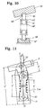
- Fig. 11 shows a well-known biasing device corresponding to the principle of Fig. 17. This will be compared with the apparatus shown in EP-A-0408169.
Landscapes
- Lock And Its Accessories (AREA)
Claims (5)
- Eine Riegelhaltevorrichtung eines Griffs (6) zum Öffnen und Schließen einer Tür, bei der ein an einer an einem Türhauptkörper (1) angebrachten Basis (20) schwenkbar befestigter Riegel (30) in einer Verriegelungsposition gehalten ist, wobei der Griff in einem Sperrzustand angeordnet ist, umfassend
ein Paar Griffhalter (24) mit einer in jedem derselben ausgebildeten Ausnehmung (24a) zum Einführen des Griffes;
einen Gelenkbolzen (25) zur drehbaren Halterung des Riegels an den Griffhaltern; und
Haltemittel (40, 44, 46a, 46b, 62') zum Halten des Riegels in der Verriegelungsposition, wenn der Griff in die besagten Griffhalter eingeführt ist, und zum Halten des Riegels in einer unverriegelten Position, wenn der Griff von den Griffhaltern getrennt ist, und wobei, wenn das Haltemittel zwischen Stiften in dem Riegel bzw. der Basis vorgesehene Vorspannmittel umfaßt, die Stifte im wesentlichen zusammenfallende Achsen aufweisen, wenn der Riegel in seiner gesperrten und in seiner ungesperrten Position gehalten ist. - Die Vorrichtung nach Anspruch 1, bei der das Haltemittel
eine Drückvorrichtung (40), die eine Druckfeder (43) und Bolzen oder Stifte (41) auf beiden Seiten dieser Druckfeder umfaßt, wobei die Drückvorrichtung in eine in dem Riegel (30) in einer Position unterhalb des Gelenkbolzens (25) - und parallel zum Gelenkbolzen liegend - vorgesehene Bohrung (42) eingefügt ist; und
in den Griffhaltern vorgesehene Ausnehmungen (41a, 41b), um durch die Stifte an beiden Seiten der Drückvorrichtung ein- und ausgekuppelt werden zu können, wobei die Ausnehmungen jeweils der verriegelten bzw. der unverriegelten Position des Riegels entsprechen, umfaßt. - Die Vorrichtung nach Anspruch 1, bei der das Haltemittel
zwei auf dem Riegel (30) in Positionen auf einer Innenseite von diesem unter dem Gelenkbolzen (25) vorgesehene Vorsprünge (33a, 33b), die auf identischen Radien, die den Gelenkbolzen als Zentrum haben, vorgesehen sind; und
eine rittlings auf einem in der Basis angeordneten Rezeß (46) vorgesehene und den Vorsprüngen entsprechende Blattfeder (44), die zwei zwischen sich einen Rezeß (44c) bildende Vorsprünge (44a, 44b) aufweist,
umfaßt. - Die Vorrichtung nach Anspruch 1, bei der das Haltemittel
in oberen und unteren Positionen des Riegels (30) oder in oberen und unteren Positionen der Basis (20) eingelassene Magnete (46a, 46b), die den Riegel an die Basis anziehen, um den Riegel in Stellungen entsprechend der verriegelten Position und der unverriegelten Position des Riegels zu halten, umfaßt. - Die Vorrichtung nach Anspruch 1, bei der das Haltemittel zwischen der Basis (20) und dem Riegel (30) eines Abschnitts unterhalb des Gelenkbolzens (25) vorgesehen ist und den Riegel derart abstützt, daß er nach oben und unten geschwenkt werden kann, und bei der das Haltemittel ein Paar Federsitze (18') mit Stiften (55'), die in an gegenüberliegenden Stellen in der Basis und dem Riegel eines Abschnitts unterhalb des den Riegel tragenden Gelenkbolzens gebildete Rezesse (59') derart eingreifen, daß der Riegel auf- und abwärts geschwenkt werden kann, und eine zwischen an jenen Federsitzen gebildeten Federauflagerungsflanschen (60') eingefügte Feder (68') umfaßt, wobei der Riegel in der verriegelten oder der unverriegelten Position durch Drehen des Riegels um den Gelenkbolzen derart gehalten wird, daß eine Linie zwischen den Mittelpunkten der Rezesse in ein oder zwei zueinander entgegengesetzten Richtungen von einer Linie zwischen dem Gelenkbolzen und dem Mittelpunkt des in der Basis gebildeten Rezesses abweicht.
Applications Claiming Priority (4)
| Application Number | Priority Date | Filing Date | Title |
|---|---|---|---|
| JP92190/89U | 1989-08-07 | ||
| JP1989092189U JPH0712560Y2 (ja) | 1989-08-07 | 1989-08-07 | 施錠装置等に於る付勢装置 |
| JP92189/89U | 1989-08-07 | ||
| JP9219089U JPH0640809Y2 (ja) | 1989-08-07 | 1989-08-07 | 扉開閉用ハンドルの掛金装置 |
Publications (2)
| Publication Number | Publication Date |
|---|---|
| EP0412632A1 EP0412632A1 (de) | 1991-02-13 |
| EP0412632B1 true EP0412632B1 (de) | 1994-09-14 |
Family
ID=26433657
Family Applications (1)
| Application Number | Title | Priority Date | Filing Date |
|---|---|---|---|
| EP90303488A Expired - Lifetime EP0412632B1 (de) | 1989-08-07 | 1990-03-30 | Vorrichtung für die Halterung des Schlosses eines Griffs zum Öffnen und Schliessen einer Türe |
Country Status (2)
| Country | Link |
|---|---|
| EP (1) | EP0412632B1 (de) |
| DE (1) | DE69012481T2 (de) |
Families Citing this family (1)
| Publication number | Priority date | Publication date | Assignee | Title |
|---|---|---|---|---|
| FR2743105B1 (fr) * | 1995-12-29 | 1999-04-02 | Pommier & Cie | Serrure a verrou a claquer |
Family Cites Families (6)
| Publication number | Priority date | Publication date | Assignee | Title |
|---|---|---|---|---|
| US1627752A (en) * | 1925-09-22 | 1927-05-10 | Sylvester J Small | Door fastener |
| DE802046C (de) * | 1948-10-02 | 1951-02-01 | Daimler Benz Akt Ges | Hauben- und Deckelverschluss, insbesondere fuer Kraftfahrzeuge |
| DE1708177A1 (de) * | 1967-11-30 | 1971-04-22 | Josef Haberl | Fensterverschluss mit frei wirkender und gelochter Verschlussstange |
| US3476425A (en) * | 1968-02-06 | 1969-11-04 | Ridge Nassau Corp | Lever type lock |
| DE2107588A1 (de) * | 1971-02-13 | 1972-09-14 | ||
| US3895774A (en) * | 1973-11-27 | 1975-07-22 | Illinois Tool Works | Shelf support clip |
-
1990
- 1990-03-30 DE DE69012481T patent/DE69012481T2/de not_active Expired - Fee Related
- 1990-03-30 EP EP90303488A patent/EP0412632B1/de not_active Expired - Lifetime
Also Published As
| Publication number | Publication date |
|---|---|
| DE69012481T2 (de) | 1995-04-06 |
| EP0412632A1 (de) | 1991-02-13 |
| DE69012481D1 (de) | 1994-10-20 |
Similar Documents
| Publication | Publication Date | Title |
|---|---|---|
| KR100396988B1 (ko) | 스쿠터형 차량의 시트 부착 구조 | |
| US5069491A (en) | Vehicle door lock system | |
| US4793163A (en) | Hasp-type latch and method of making and using same | |
| US6962375B2 (en) | Rotary latches | |
| US6109668A (en) | Window lock | |
| US6857298B2 (en) | Double action push button locking system | |
| US20030111845A1 (en) | Paddle lock having slim profile | |
| US6309008B1 (en) | Pull handle mechanism for vehicle caps and the like | |
| CN1894124B (zh) | 具有锁定把手的转动爪锁栓 | |
| US4382620A (en) | Panic handle for doors | |
| KR20010023939A (ko) | 역회전 방지 폴 래치 | |
| US6048005A (en) | Striker extender for pivotally opening rear windows of motor vehicles | |
| EP0412632B1 (de) | Vorrichtung für die Halterung des Schlosses eines Griffs zum Öffnen und Schliessen einer Türe | |
| US7748245B2 (en) | Rotary pawl latch | |
| US5505065A (en) | Latch for luggage, containers or the like | |
| EP0408169B1 (de) | Verriegelungskonstruktion eines Griffes für das Schliessen und Öffnen einer Türe | |
| JPH0343576A (ja) | 扉開閉用ハンドルの掛金装置 | |
| CN1087157C (zh) | 箱包用的闭锁装置 | |
| JPH0738008Y2 (ja) | 車両用荷物棚ケース | |
| US20250243688A1 (en) | Combination lock for locking a closure member | |
| JP3481873B2 (ja) | ロッド棒ロック装置 | |
| WO2008148153A1 (en) | Locking mechanism | |
| JPH0748917Y2 (ja) | 扉開閉用ハンドルの掛金装置 | |
| EP1125773A2 (de) | Antidiebstahlvorrichtung | |
| US4986577A (en) | Security lock mechanism |
Legal Events
| Date | Code | Title | Description |
|---|---|---|---|
| PUAI | Public reference made under article 153(3) epc to a published international application that has entered the european phase |
Free format text: ORIGINAL CODE: 0009012 |
|
| AK | Designated contracting states |
Kind code of ref document: A1 Designated state(s): DE FR GB IT |
|
| 17P | Request for examination filed |
Effective date: 19910719 |
|
| 17Q | First examination report despatched |
Effective date: 19930127 |
|
| GRAA | (expected) grant |
Free format text: ORIGINAL CODE: 0009210 |
|
| AK | Designated contracting states |
Kind code of ref document: B1 Designated state(s): DE FR GB IT |
|
| REF | Corresponds to: |
Ref document number: 69012481 Country of ref document: DE Date of ref document: 19941020 |
|
| ITF | It: translation for a ep patent filed | ||
| ET | Fr: translation filed | ||
| PLBE | No opposition filed within time limit |
Free format text: ORIGINAL CODE: 0009261 |
|
| STAA | Information on the status of an ep patent application or granted ep patent |
Free format text: STATUS: NO OPPOSITION FILED WITHIN TIME LIMIT |
|
| 26N | No opposition filed | ||
| PGFP | Annual fee paid to national office [announced via postgrant information from national office to epo] |
Ref country code: FR Payment date: 19960315 Year of fee payment: 7 |
|
| PGFP | Annual fee paid to national office [announced via postgrant information from national office to epo] |
Ref country code: GB Payment date: 19960321 Year of fee payment: 7 |
|
| PGFP | Annual fee paid to national office [announced via postgrant information from national office to epo] |
Ref country code: DE Payment date: 19960328 Year of fee payment: 7 |
|
| PG25 | Lapsed in a contracting state [announced via postgrant information from national office to epo] |
Ref country code: GB Effective date: 19970330 |
|
| GBPC | Gb: european patent ceased through non-payment of renewal fee |
Effective date: 19970330 |
|
| PG25 | Lapsed in a contracting state [announced via postgrant information from national office to epo] |
Ref country code: FR Free format text: LAPSE BECAUSE OF NON-PAYMENT OF DUE FEES Effective date: 19971128 |
|
| PG25 | Lapsed in a contracting state [announced via postgrant information from national office to epo] |
Ref country code: DE Effective date: 19971202 |
|
| REG | Reference to a national code |
Ref country code: FR Ref legal event code: ST |
|
| PG25 | Lapsed in a contracting state [announced via postgrant information from national office to epo] |
Ref country code: IT Free format text: LAPSE BECAUSE OF NON-PAYMENT OF DUE FEES;WARNING: LAPSES OF ITALIAN PATENTS WITH EFFECTIVE DATE BEFORE 2007 MAY HAVE OCCURRED AT ANY TIME BEFORE 2007. THE CORRECT EFFECTIVE DATE MAY BE DIFFERENT FROM THE ONE RECORDED. Effective date: 20050330 |