EP0412780A2 - Méthode et dispositif pour mesurer la puissance de véhicule - Google Patents
Méthode et dispositif pour mesurer la puissance de véhicule Download PDFInfo
- Publication number
- EP0412780A2 EP0412780A2 EP90308684A EP90308684A EP0412780A2 EP 0412780 A2 EP0412780 A2 EP 0412780A2 EP 90308684 A EP90308684 A EP 90308684A EP 90308684 A EP90308684 A EP 90308684A EP 0412780 A2 EP0412780 A2 EP 0412780A2
- Authority
- EP
- European Patent Office
- Prior art keywords
- measuring
- velocity
- force
- vehicle
- measured
- Prior art date
- Legal status (The legal status is an assumption and is not a legal conclusion. Google has not performed a legal analysis and makes no representation as to the accuracy of the status listed.)
- Withdrawn
Links
Images
Classifications
-
- G—PHYSICS
- G01—MEASURING; TESTING
- G01G—WEIGHING
- G01G19/00—Weighing apparatus or methods adapted for special purposes not provided for in the preceding groups
- G01G19/02—Weighing apparatus or methods adapted for special purposes not provided for in the preceding groups for weighing wheeled or rolling bodies, e.g. vehicles
- G01G19/03—Weighing apparatus or methods adapted for special purposes not provided for in the preceding groups for weighing wheeled or rolling bodies, e.g. vehicles for weighing during motion
-
- G—PHYSICS
- G01—MEASURING; TESTING
- G01L—MEASURING FORCE, STRESS, TORQUE, WORK, MECHANICAL POWER, MECHANICAL EFFICIENCY, OR FLUID PRESSURE
- G01L3/00—Measuring torque, work, mechanical power, or mechanical efficiency, in general
- G01L3/24—Devices for determining the value of power, e.g. by measuring and simultaneously multiplying the values of torque and revolutions per unit of time, by multiplying the values of tractive or propulsive force and velocity
- G01L3/242—Devices for determining the value of power, e.g. by measuring and simultaneously multiplying the values of torque and revolutions per unit of time, by multiplying the values of tractive or propulsive force and velocity by measuring and simultaneously multiplying torque and velocity
-
- F—MECHANICAL ENGINEERING; LIGHTING; HEATING; WEAPONS; BLASTING
- F02—COMBUSTION ENGINES; HOT-GAS OR COMBUSTION-PRODUCT ENGINE PLANTS
- F02B—INTERNAL-COMBUSTION PISTON ENGINES; COMBUSTION ENGINES IN GENERAL
- F02B1/00—Engines characterised by fuel-air mixture compression
- F02B1/02—Engines characterised by fuel-air mixture compression with positive ignition
- F02B1/04—Engines characterised by fuel-air mixture compression with positive ignition with fuel-air mixture admission into cylinder
Definitions
- This invention relates to measuring vehicle engine power.
- the power output of an engine can be bench-measured to give a brake horse-power figure which can be related to engine speed. This however may bear little relationship to the power of the engine in actual driving conditions and is in any event not useful for monitoring engine performance under actual driving conditions when performance-related parameters may change, such for example as ambient temperature, fuel mixture, spark-plug timing (in petrol engines) and so on.
- the present invention provides a method and apparatus for measuring engine power not subject to these disadvantages.
- the invention comprises a method for measuring the power output of a vehicle engine comprising measuring the force produced by the engine and the velocity of the vehicle and evaluating the power from said measurement.
- the force may be measured by measuring deformation or displacement of a drive train member such for example as twisting of a propellor shaft. Such may be measured by measuring a time delay between peripheral marks at axially-spaced positions on said shaft passing fixed sensors.
- the marks may comprise magnetic marks, the sensors then being adapted to detect same.
- the velocity may be measured by a regular vehicle speedometer, or by measuring the rotational velocity of said drive train member, as by measuring the frequency with which one of said peripheral marks passes one of said fixed sensors - since one is in any event sensing passage of such mark in order to measure force one might as well utilise the signal therefrom in a speed-measuring arrangement.
- the invention also comprises apparatus for measuring the power output of a vehicle engine comprising engine force measuring means and vehicle velocity measuring means and evaluating means evaluating the said power output from the measured force and velocity.
- the method and apparatus will be capable of giving a useful and continuous indication of engine power output under driving conditions and this will be useful in monitoring engine performance especially in high performance e.g. racing and rallying vehicles, in trucks, in trains and tanks as well as in boats and airplanes.
- the drawings illustrate methods and apparatus for measuring the power output of a vehicle engine comprising measuring the force produced by the engine and the velocity of the vehicle and evaluating the power from such measurement essentially by multiplying the measured force by the measured velocity.
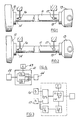
- Figures 1 and 2 illustrate measuring the driving force by measuring deformation of a drive train member namely the propellor shaft 11 of a road vehicle.
- a drive train member namely the propellor shaft 11 of a road vehicle.
- the shaft 11 transmits driving power from the gearbox 12 to the axle 13 it twists under the transmitted torque.
- the extent of twisting is reasonably linear with respect to the torque.
- Magnetic markers 14,15 are mounted on the shaft 11 at opposite ends thereof. It is convenient to regard them as being aligned (though it is not essential that they are) when the shaft 11 is in its normal, i.e. untwisted condition.
- Fixed, aligned sensors 16,17 are mounted adjacent the locations of the magnetic markers 14,15 to sense when they pass as the shaft 11 rotates. The aligned markers and sensors will give rise to simultaneous output signals from the sensors 16,17 so long as the shaft 11 is not loaded. Once power is transmitted however, the shaft 11 will twist proportionally to the torque and hence the force which drives the vehicle.
- the twisting will delay the signal from sensor 17 as compared to that from sensor 16 by a time interval proportional to the twisting, and hence proportional to the force.
- the delay will also be inversely proportional to the shaft rotational speed.
- a measure of that speed can be obtained from the frequency of pulses from one of the sensors 16,17, and this will serve also to generate a vehicle velocity value, velocity being proportional to that frequency.
- the vehicle will usually have an accurate speedometer and a velocity signal can be taken from this.
- a force signal from the time delay between the sensors and a velocity signal are multiplied together, as by deriving digital values and multiplying them in a microprocessor together with a constant to give an engine power signal.
- the constant can be determined by a calibration procedure and selected according to the units in which the power output is required to be displayed. There can of course be provided means for using different constants to display the power output in different units.
- Figure 3 illustrates this diagrammatically, time signals from sensors 16,17 being fed to a microprocessor 3, which derives the delay t2-t1, and a velocity measure as 1/t1, namely the frequency of pulses from sensor 17. From this is derived (1/t1)2 and then) the function K(t2-t1)/(t1) where K is a constant output from a selector 32 according to the units in which the quantity is required to be displayed on cab readout 33.
- Figure 4 illustrates an arrangement using this relationship in which the single output to a processor 41 is from a speedometer 42 which could of course be one of the sensors 16,17 referred to above.
- a constant K is supplied as before from a selector 43 and displayed on a cab readout 44.
- the speedometer signal can be a voltage and the differentation effected in a simple capacitor/resistor differentiating circuit.
Landscapes
- Physics & Mathematics (AREA)
- General Physics & Mathematics (AREA)
- Chemical & Material Sciences (AREA)
- Engineering & Computer Science (AREA)
- Combustion & Propulsion (AREA)
- Force Measurement Appropriate To Specific Purposes (AREA)
Applications Claiming Priority (2)
| Application Number | Priority Date | Filing Date | Title |
|---|---|---|---|
| GB8918367 | 1989-08-11 | ||
| GB898918367A GB8918367D0 (en) | 1989-08-11 | 1989-08-11 | Method and apparatus for measuring vehicle power |
Publications (2)
| Publication Number | Publication Date |
|---|---|
| EP0412780A2 true EP0412780A2 (fr) | 1991-02-13 |
| EP0412780A3 EP0412780A3 (en) | 1991-12-27 |
Family
ID=10661493
Family Applications (1)
| Application Number | Title | Priority Date | Filing Date |
|---|---|---|---|
| EP19900308684 Withdrawn EP0412780A3 (en) | 1989-08-11 | 1990-08-07 | Method and apparatus for measuring vehicle power |
Country Status (5)
| Country | Link |
|---|---|
| EP (1) | EP0412780A3 (fr) |
| JP (1) | JPH0378635A (fr) |
| GB (2) | GB8918367D0 (fr) |
| IE (1) | IE902863A1 (fr) |
| PT (1) | PT94965A (fr) |
Cited By (3)
| Publication number | Priority date | Publication date | Assignee | Title |
|---|---|---|---|---|
| WO1996020395A1 (fr) * | 1994-12-27 | 1996-07-04 | Siemens Aktiengesellschaft | Procede et dispositif permettant de determiner une puissance |
| EP2463664A1 (fr) * | 2010-12-09 | 2012-06-13 | Turner Powertrain Systems Limited | Mesure de la vitesse, de déplacement, de la position ou du mouvement angulaires d'arbre |
| CN107923803A (zh) * | 2015-10-20 | 2018-04-17 | 伊格尔工业股份有限公司 | 非接触式扭矩测量方法 |
Family Cites Families (16)
| Publication number | Priority date | Publication date | Assignee | Title |
|---|---|---|---|---|
| GB417051A (en) * | 1933-03-21 | 1934-09-21 | Alan Stewart Fitzgerald | Improvements in or relating to dynamometric apparatus |
| GB472690A (en) * | 1936-03-28 | 1937-09-28 | William Albert White | Improvements in and relating to torsiometer devices |
| GB553830A (en) * | 1940-11-09 | 1943-06-08 | Square D Co | A device for indicating the power-output of engines |
| US2365073A (en) * | 1942-03-06 | 1944-12-12 | H D Mallison | Means for indicating horsepower and horsepower factors |
| GB595418A (en) * | 1942-11-19 | 1947-12-04 | Westinghouse Electric Int Co | Improvements in or relating to systems for continuously measuring the power output of a rotating shaft |
| GB578859A (en) * | 1944-04-13 | 1946-07-15 | Westinghouse Electric Int Co | Improvements in or relating to power indicating or measuring devices |
| GB703531A (en) * | 1951-01-20 | 1954-02-03 | Jeyaretnam Thillaimuthu | A direct reading transmission dynamometer |
| DE959765C (de) * | 1953-08-04 | 1957-03-14 | Licentia Gmbh | Produktintegrator als Arbeitsmesser fuer Antriebsfahrzeuge z.B. Lokomotiven |
| US3274826A (en) * | 1962-09-28 | 1966-09-27 | Ingram Maxwell | Direct reading shaft horsepower meter systems |
| GB1187044A (en) * | 1967-04-25 | 1970-04-08 | Migirdic Keteon Caylakian | Improvements in or relating to Appratus for Measuring the Instantaneous Power Transmitted by a Rotatable Shaft. |
| US3972224A (en) * | 1974-05-14 | 1976-08-03 | Maxwell Ingram | Shaft efficiency monitoring system |
| CH591074A5 (fr) * | 1975-02-07 | 1977-08-31 | Witschi Ernst | |
| US4100794A (en) * | 1976-12-06 | 1978-07-18 | Borg-Warner Corporation | System for measuring torque and speed of rotating shaft |
| DE2904056C2 (de) * | 1979-02-02 | 1983-07-28 | Gebr. Hofmann Gmbh & Co Kg Maschinenfabrik, 6100 Darmstadt | Verfahren und Schaltungsanordnung zur dynamischen Messung der Ausgangsleistung von motorangetriebenen Fahrzeugen, insbesondere der Leistung eines Kraftfahrzeuges |
| US4450728A (en) * | 1981-10-06 | 1984-05-29 | Horiba Instruments Incorporated | Vehicle force measurement system |
| DE3722728C1 (en) * | 1987-07-09 | 1988-12-08 | Ulrich Schoberer | Work meter for a crank drive |
-
1989
- 1989-08-11 GB GB898918367A patent/GB8918367D0/en active Pending
-
1990
- 1990-08-07 GB GB9017304A patent/GB2234827A/en not_active Withdrawn
- 1990-08-07 EP EP19900308684 patent/EP0412780A3/en not_active Withdrawn
- 1990-08-08 IE IE286390A patent/IE902863A1/en unknown
- 1990-08-08 JP JP21011590A patent/JPH0378635A/ja active Pending
- 1990-08-10 PT PT9496590A patent/PT94965A/pt not_active Application Discontinuation
Cited By (6)
| Publication number | Priority date | Publication date | Assignee | Title |
|---|---|---|---|---|
| WO1996020395A1 (fr) * | 1994-12-27 | 1996-07-04 | Siemens Aktiengesellschaft | Procede et dispositif permettant de determiner une puissance |
| US5979248A (en) * | 1994-12-27 | 1999-11-09 | Siemens Aktiengesellschaft | Method and device for determining a power |
| EP2463664A1 (fr) * | 2010-12-09 | 2012-06-13 | Turner Powertrain Systems Limited | Mesure de la vitesse, de déplacement, de la position ou du mouvement angulaires d'arbre |
| US9091703B2 (en) | 2010-12-09 | 2015-07-28 | Turner Powertrain Systems Limited | Measurement of shaft speed, angular displacement, position or movement |
| CN107923803A (zh) * | 2015-10-20 | 2018-04-17 | 伊格尔工业股份有限公司 | 非接触式扭矩测量方法 |
| EP3367080A4 (fr) * | 2015-10-20 | 2018-10-17 | Eagle Industry Co., Ltd. | Procédé sans contact pour mesure de couple |
Also Published As
| Publication number | Publication date |
|---|---|
| PT94965A (pt) | 1992-04-30 |
| JPH0378635A (ja) | 1991-04-03 |
| GB2234827A (en) | 1991-02-13 |
| EP0412780A3 (en) | 1991-12-27 |
| IE902863A1 (en) | 1991-02-27 |
| GB8918367D0 (en) | 1989-09-20 |
| GB9017304D0 (en) | 1990-09-19 |
Similar Documents
| Publication | Publication Date | Title |
|---|---|---|
| US5215154A (en) | Method and apparatus for measuring vehicle weight or engine power or both | |
| US5686651A (en) | Method for measuring vehicle motion resistances using short distance coast-down test based on the distance-time data | |
| US6694245B2 (en) | Vehicle state analysis system and its analysis method | |
| CA1087873A (fr) | Banc d'essai pour vehicules automobiles | |
| US4466294A (en) | Transient driving cycle simulator test system | |
| US4169371A (en) | Method and apparatus for measuring drive system characteristic data in dynamic operation | |
| JPH02201240A (ja) | 自動車の質量検出装置 | |
| KR0170543B1 (ko) | 토션 토크 검출 장치, 미끄럼 검출 장치, 도로 마찰 계수 검출 장치 및 토션 토크 검출 방법 | |
| US3921446A (en) | Method of measuring torque | |
| SE8200184L (sv) | Forfarande och anordning for indikering av rekommenderade vexellegen vid med flerstegsvexellada forsedda motorfordon | |
| WO1984002311A1 (fr) | Procede et dispositif servant a signaler qu'un changement de rapport de vitesse est necessaire | |
| EP0356067A2 (fr) | Pesage de véhicules | |
| US4450728A (en) | Vehicle force measurement system | |
| US5335537A (en) | Method of inspecting limited slip differential for vehicle | |
| EP0412780A2 (fr) | Méthode et dispositif pour mesurer la puissance de véhicule | |
| US4716872A (en) | Economic speed indicator | |
| US3905225A (en) | Vehicle testing apparatus and method | |
| US20020134147A1 (en) | On-board dynamometer | |
| US3853002A (en) | Vehicular performance analyzer | |
| US4914945A (en) | Vessel speed detecting device | |
| ATE28601T1 (de) | Kontrolleinrichtung fuer ein fahrzeuggetriebe zur feststellung des wirtschaftlichen fahrbereichs. | |
| JP2777943B2 (ja) | 自動車のトラクションコントロール及び差動制限機構の検査方法 | |
| Passmore et al. | Measuring vehicle drag forces using an on-board microcomputer | |
| US6324483B1 (en) | Angular acceleration transducer | |
| SU1739221A1 (ru) | Способ определени работы транспортного средства |
Legal Events
| Date | Code | Title | Description |
|---|---|---|---|
| PUAI | Public reference made under article 153(3) epc to a published international application that has entered the european phase |
Free format text: ORIGINAL CODE: 0009012 |
|
| AK | Designated contracting states |
Kind code of ref document: A2 Designated state(s): AT BE CH DE DK ES FR GB GR IT LI LU NL SE |
|
| PUAL | Search report despatched |
Free format text: ORIGINAL CODE: 0009013 |
|
| AK | Designated contracting states |
Kind code of ref document: A3 Designated state(s): AT BE CH DE DK ES FR GB GR IT LI LU NL SE |
|
| STAA | Information on the status of an ep patent application or granted ep patent |
Free format text: STATUS: THE APPLICATION IS DEEMED TO BE WITHDRAWN |
|
| 18D | Application deemed to be withdrawn |
Effective date: 19920629 |