EP0412819A2 - Bilderzeugung mittels magnetischer Kernresonanz - Google Patents
Bilderzeugung mittels magnetischer Kernresonanz Download PDFInfo
- Publication number
- EP0412819A2 EP0412819A2 EP90308774A EP90308774A EP0412819A2 EP 0412819 A2 EP0412819 A2 EP 0412819A2 EP 90308774 A EP90308774 A EP 90308774A EP 90308774 A EP90308774 A EP 90308774A EP 0412819 A2 EP0412819 A2 EP 0412819A2
- Authority
- EP
- European Patent Office
- Prior art keywords
- sample
- probe beam
- magnetic field
- nmr
- gradient
- Prior art date
- Legal status (The legal status is an assumption and is not a legal conclusion. Google has not performed a legal analysis and makes no representation as to the accuracy of the status listed.)
- Withdrawn
Links
Images



Classifications
-
- G—PHYSICS
- G01—MEASURING; TESTING
- G01R—MEASURING ELECTRIC VARIABLES; MEASURING MAGNETIC VARIABLES
- G01R33/00—Arrangements or instruments for measuring magnetic variables
- G01R33/20—Arrangements or instruments for measuring magnetic variables involving magnetic resonance
- G01R33/44—Arrangements or instruments for measuring magnetic variables involving magnetic resonance using nuclear magnetic resonance [NMR]
- G01R33/48—NMR imaging systems
- G01R33/54—Signal processing systems, e.g. using pulse sequences ; Generation or control of pulse sequences; Operator console
- G01R33/56—Image enhancement or correction, e.g. subtraction or averaging techniques, e.g. improvement of signal-to-noise ratio and resolution
- G01R33/567—Image enhancement or correction, e.g. subtraction or averaging techniques, e.g. improvement of signal-to-noise ratio and resolution gated by physiological signals, i.e. synchronization of acquired MR data with periodical motion of an object of interest, e.g. monitoring or triggering system for cardiac or respiratory gating
- G01R33/5676—Gating or triggering based on an MR signal, e.g. involving one or more navigator echoes for motion monitoring and correction
-
- G—PHYSICS
- G01—MEASURING; TESTING
- G01R—MEASURING ELECTRIC VARIABLES; MEASURING MAGNETIC VARIABLES
- G01R33/00—Arrangements or instruments for measuring magnetic variables
- G01R33/20—Arrangements or instruments for measuring magnetic variables involving magnetic resonance
- G01R33/44—Arrangements or instruments for measuring magnetic variables involving magnetic resonance using nuclear magnetic resonance [NMR]
- G01R33/48—NMR imaging systems
- G01R33/483—NMR imaging systems with selection of signals or spectra from particular regions of the volume, e.g. in vivo spectroscopy
- G01R33/4833—NMR imaging systems with selection of signals or spectra from particular regions of the volume, e.g. in vivo spectroscopy using spatially selective excitation of the volume of interest, e.g. selecting non-orthogonal or inclined slices
- G01R33/4836—NMR imaging systems with selection of signals or spectra from particular regions of the volume, e.g. in vivo spectroscopy using spatially selective excitation of the volume of interest, e.g. selecting non-orthogonal or inclined slices using an RF pulse being spatially selective in more than one spatial dimension, e.g. a 2D pencil-beam excitation pulse
-
- G—PHYSICS
- G01—MEASURING; TESTING
- G01R—MEASURING ELECTRIC VARIABLES; MEASURING MAGNETIC VARIABLES
- G01R33/00—Arrangements or instruments for measuring magnetic variables
- G01R33/20—Arrangements or instruments for measuring magnetic variables involving magnetic resonance
- G01R33/44—Arrangements or instruments for measuring magnetic variables involving magnetic resonance using nuclear magnetic resonance [NMR]
- G01R33/446—Multifrequency selective RF pulses, e.g. multinuclear acquisition mode
-
- G—PHYSICS
- G01—MEASURING; TESTING
- G01R—MEASURING ELECTRIC VARIABLES; MEASURING MAGNETIC VARIABLES
- G01R33/00—Arrangements or instruments for measuring magnetic variables
- G01R33/20—Arrangements or instruments for measuring magnetic variables involving magnetic resonance
- G01R33/44—Arrangements or instruments for measuring magnetic variables involving magnetic resonance using nuclear magnetic resonance [NMR]
- G01R33/48—NMR imaging systems
- G01R33/4818—MR characterised by data acquisition along a specific k-space trajectory or by the temporal order of k-space coverage, e.g. centric or segmented coverage of k-space
- G01R33/4824—MR characterised by data acquisition along a specific k-space trajectory or by the temporal order of k-space coverage, e.g. centric or segmented coverage of k-space using a non-Cartesian trajectory
-
- G—PHYSICS
- G01—MEASURING; TESTING
- G01R—MEASURING ELECTRIC VARIABLES; MEASURING MAGNETIC VARIABLES
- G01R33/00—Arrangements or instruments for measuring magnetic variables
- G01R33/20—Arrangements or instruments for measuring magnetic variables involving magnetic resonance
- G01R33/44—Arrangements or instruments for measuring magnetic variables involving magnetic resonance using nuclear magnetic resonance [NMR]
- G01R33/48—NMR imaging systems
- G01R33/54—Signal processing systems, e.g. using pulse sequences ; Generation or control of pulse sequences; Operator console
- G01R33/56—Image enhancement or correction, e.g. subtraction or averaging techniques, e.g. improvement of signal-to-noise ratio and resolution
- G01R33/561—Image enhancement or correction, e.g. subtraction or averaging techniques, e.g. improvement of signal-to-noise ratio and resolution by reduction of the scanning time, i.e. fast acquiring systems, e.g. using echo-planar pulse sequences
- G01R33/5615—Echo train techniques involving acquiring plural, differently encoded, echo signals after one RF excitation, e.g. using gradient refocusing in echo planar imaging [EPI], RF refocusing in rapid acquisition with relaxation enhancement [RARE] or using both RF and gradient refocusing in gradient and spin echo imaging [GRASE]
- G01R33/5617—Echo train techniques involving acquiring plural, differently encoded, echo signals after one RF excitation, e.g. using gradient refocusing in echo planar imaging [EPI], RF refocusing in rapid acquisition with relaxation enhancement [RARE] or using both RF and gradient refocusing in gradient and spin echo imaging [GRASE] using RF refocusing, e.g. RARE
-
- G—PHYSICS
- G01—MEASURING; TESTING
- G01R—MEASURING ELECTRIC VARIABLES; MEASURING MAGNETIC VARIABLES
- G01R33/00—Arrangements or instruments for measuring magnetic variables
- G01R33/20—Arrangements or instruments for measuring magnetic variables involving magnetic resonance
- G01R33/44—Arrangements or instruments for measuring magnetic variables involving magnetic resonance using nuclear magnetic resonance [NMR]
- G01R33/48—NMR imaging systems
- G01R33/54—Signal processing systems, e.g. using pulse sequences ; Generation or control of pulse sequences; Operator console
- G01R33/56—Image enhancement or correction, e.g. subtraction or averaging techniques, e.g. improvement of signal-to-noise ratio and resolution
- G01R33/563—Image enhancement or correction, e.g. subtraction or averaging techniques, e.g. improvement of signal-to-noise ratio and resolution of moving material, e.g. flow contrast angiography
- G01R33/56308—Characterization of motion or flow; Dynamic imaging
Definitions
- the present invention relates to nuclear magnetic resonance (NMR) imaging and, for example, to apparatus and methods for providing rapidly-obtained NMR profile images of cardiac wall and/or valve motion.
- NMR nuclear magnetic resonance
- ultrasound echocardiography which provides a reasonably fast and interactive means to access cardiac motion and provide a relatively thorough investigation of the heart, with relatively low risk to the patient.
- ultrasound echocardiography is limited to viewing of the heart from positions (through "windows) between the patient's ribs, as the relatively dense rib bones substantially interfere with ultrasound propagation.
- Present medical clinical practice generally includes a M-mode examination as part of a complete cardiac study.
- M-mode ultrasound echocardiography a continuous plot of the time-varying position of tissue interfaces, observed along a one-dimensional axis, is provided by the motion of the cardiac portion (walls and/or valve) to be imaged, moving with respect to a stationary pencil-shaped beam of ultrasound energy.
- a M-mode imaging method utilizing a modality other than ultrasound, which provides all of the features thereof, to access wall and/or valve motion, without being limited to windows provided through anatomical portions of differing density in the patient to be imaged, and yet still allowing accurate beam positioning and suitable contrast to be obtained.
- a noninvasive NMR cardiac examination allows well known NMR imaging techniques to be utilized to provide excellent overall images of the heart and define image coordinates and angles with respect thereto
- a substantially continuous image recording motion of a portion of a sample is provided by: first NMR exciting a relatively narrow cylindrical region, typically with diameter less than 1 inch, of magnetization intersecting the sample to be imaged.
- a rotating-gradient (p) pulse signal which reorients a magnetic field gradient through two dimensions during the course of a RF excitation pulse, is presently preferred.
- the NMR response signal thus excited is then acquired in the presence of a readout gradient oriented along the length of the cylindrical excitation beam and establishing position thereon.
- a Fourier transformation of the acquired data is applied.
- the resulting data is a real-time record of the profile of the sample along the axis of the cylindrical probe beam.
- the cylinder-beam axis can be oriented in an arbitrary direction by proper mixing of the excitation and readout gradient fields; use of three orthogonal gradients in a Cartesian coordinate system is presently preferred. Spatial offsetting of the cylindrical beam, from the center of the static magnetic field of the NMR imaging system, to any specific location within the system's imaging volume, can be obtained by frequency modulation of the p pulse RF wave form.
- a typical pulse duration of about 7 milliseconds is utilized for achieving a 1 cm. beam diameter.
- Sequence repetition time T R of about 30 msec. yields at least 30 profiles per second, which profile data are plotted in a series of rows to create a recording of the changing profile with time.
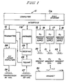
- FIG. 1 is a simplified block diagram of the major components of an NMR imaging system suitable for use with the NMR pulse sequences of the invention described herein.
- the system 10 is made up of a general purpose mini-computer 11 which is functionally coupled to a disk storage unit 11 a and an interface unit 11b.
- An RF transmitter 12, signal averager 14, and gradient power supplies 16, 17 and 18 for respectively energizing X, Y and Z gradient coils 20, 21 and 22, are all coupled to computer 11 through interface unit 11 b.
- RF transmitter 12 is gated with pulse envelopes from computer 11 to generate RF pulses having the required modulation to excite nuclear resonance in the object under study.
- the RF pulses are amplified in RF power amplifier 24 to levels varying from 100 watts to several kilowatts, depending on the imaging method, and applied to transmitter coil 26. The higher power levels are necessary for large sample volumes, such as in whole body imaging, and where short duration pulses are required to excite large NMR frequency bandwidths.
- the NMR signal is sensed by receiver coil 27, amplified in a low noise preamplifier 28 and applied for further amplification, detection, and filtering to receiver 29.
- the signal is then digitized for averaging by signal averager 14 and for processing by computer 11.
- Pre-amplifier 28 and receiver 29 are protected from the RF pulses during transmission by active gating or by passive filtering.
- Computer 11 provides gating and envelope modulation for the NMR pulses, blanking for the preamplifier and RF power amplifier, and voltage waveforms for the gradient power supplies.
- the computer also performs data processing such as Fourier transforms, image reconstruction, data filtering, imaging display, and storage functions.
- the transmitter and receiver RF coils may comprise a single coil.
- two separate coils that are electrically orthogonal may be used.
- the latter configuration has the advantage of reduced RF pulse breakthrough into the receiver during pulse transmission.
- the coils are orthogonal to the direction of a static magnetic field B o produced by a magnet means 30.
- the coils may be isolated from the remainder of the system by enclosure in an RF shielded cage.
- Magnetic field gradient coils 20, 21 and 22 are necessary to provide gradients G x , Gy, and G z , respectively.
- the gradients should be monotonic and linear over the sample volume.
- Multivalued gradient fields cause a degradation in the NMR signal data, known as aliasing, which leads to severe image artifacts.
- Nonlinear gradients cause geometric distortions of the image.
- a typical use for the imaging method of the present invention is to derive continuous real-time profiles of the motion of a desired portion (wall and/or valves) in the heart 30 of a human subject.
- a selectively-excited probe "beam” 31 (or cylindrical excitation pattern) is so directed as to pass through the desired portions of the sample; here, the beam passes into right side wall 30r of the sample heart, thence sequentially through the right ventricle, the septum and left ventricle thereof, exiting through the left heart wall 30 1.
- Beam 31 is so angled and placed as to be substantially normal to the cardiac septum S, in this view.
- the NMR magnetic field gradient and RF signals (which establish the beam properties), are not substantially attenuated or otherwise modified by changes in density of portions of the sample, there are no particular "windows" to be located and utilized; beam 31 can be placed through any location 32 to be motion-imaged.
- the illustrative method of the present invention will return data indicating the motion of imaging location 32 on a real-time basis, with typically at least one dozen indications of the present location of imaging site 32 occurring for each beat of the cardiac sample being investigated.
- Figure 3 is a set of graphs of RF and gradient magnetic field excitation signals used to provide imaging data based upon a cylindrical probe beam 31, here extending substantially parallel to the Z-axis of the Cartesian coordinate system in the imaging volume of the NMR system magnet. This particular orientation is selected here for simplicity of description. Movement of the beam to other orientations (angular offset) with respect to the Z (longitudinal) axis of the system, and spatial offsetting from the center of the system imaging volume, can be obtained utilizing known methods, such as those described and claimed in U.S. Patent 4,812,760, issued March 14, 1989, assigned to the assignee of the present application and incorporated herein in its entirety by reference.
- This two-dimensional (2D) selective NMR inverting and refocussing set of pulses utilizes a simultaneous modulated-RF excitation pulse 34, commencing at a sequence start time to and ending at a time h ; the RF pulse has an amplitude-modulated envelope which may be symmetrical or, as shown, asymmetrical.
- a two-dimensional magnetic field gradient is applied with the gradient magnetic fields, e.g. G x and Gy, in two dimensions generating a k-space spiral that reorients itself in a manner selected to generate the desired cylindrical probe beam 31.
- the pair of gradient pulses 36 and 38 thus have amplitudes decreasing linearly with time and have a plurality, e.g., eight, of periods within the excitation time interval T e from time to to time t 1 .
- This pulse is inherently refocussed, and obviates the need for an extra gradient refocussing lobe. It has been found that these excitation pulses can be utilized even where the probe beam is tipped at large angles (even as much as 90° or more) from the Z axis of the imaging volume; it is known that probe beams can be produced which excite volumes which are the Fourier transform of a weighted trajectory through k-space with the gradient waveforms 36 and 38 following a spiral which efficiently samples k-space.
- the accompanying RF signal waveform 34 which can be normalized to the k-space velocity, serves as a weighting function for the k-space trajectory, so that the method can be used to produce a cylindrical excitation beam with a Gaussian-profile cross-section, in the manner of Pauly et al.
- the bandwidth of the pulse can thus be maximized by varying the rate of traversal of k-space subject to the constrain of the particular maximum gradient slew rate available in a particular NMR system.
- flow compensation gradient pulses 40a, 40b and 40c may be utilized in a flow-compensation time interval t c1 , from time ti to time t 2 , and an additional Z-gradient compensation lobe 42 may be provided in a second compensation time interval T c2 from time t 2 to time to.
- This addition of flow-compensating bipolar gradients inverts the contrast of flow blood and suppresses flow artifacts.
- a readout subsequence is provided in a readout time interval T r , from time t 3 to time ts, where a readout gradient G r , z signal pulse 44 is provided in the beam direction (here, in the Z direction) normal to the plane (here, normal to the x-y plane) in which the probe beam undergoes reorientation.
- a gradient-echo NMR response signal 46 is received, and gated by a valid-data acquisition gate 48 about a central echo time t4; the acquisition time interval T r may be about 8 msec. in a typical sequence with T R of about 30 msec.
- spoiler gradient signal pulses 50a and 50b may be provided in the gradients in which the reorienting magnetic field is provided for generation of the probe beam, to dephase the total magnetization and eliminate coherence prior to commencement of the next profile imaging sequence at start time to (at a repetition time T R between 30 and 50 msec., i.e. about 20 to about 33 1/3 images per second).
- the RF waveform 34 needed to excite a 2D profile P(x,y) is then chosen to provide the correct weighting of the k-space trajectory: where is the Fourier transform of P(x,y).
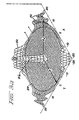
- the probe beam 31 has an aliasing excitation ring 52 at an aliasing radius R A , due to an out-of-phase component proportional to the number of cycles in the spiral and also proportional to the spot size
- This aliasing ring 52 can be seen in Figure 3b, which is an image taken in a 1.5T system of a phantom, of uniform thickness and density, illuminated by probe beam 31 of Figure 3a.
- Figure 3b is an image taken in a 1.5T system of a phantom, of uniform thickness and density, illuminated by probe beam 31 of Figure 3a.
- the spot size (diameter) of beam 31' or the number of cycles in excitation gradient waveforms 36 and 38 needs to be large enough to place ring 52 outside the moving tissue region of interest.
- the response signal can be received with a surface coil antenna 54, of radius R which is commensurate with the depth of the imaging location 32 into the sample (and below the surface coil 54 plane), and which radius R is less than the aliasing radius R A ; use of a reception surface coil also increases the signal-to-noise ratio.
- Broadband pulses have been designed by varying the rate of traversal of the k-space trajectory to match the maximum slew rate over the course of the pulse. This yields a pulse with identical excitation characteristics on resonance but with twice the bandwidth of the constant-angular-rate pulse.
- the RF excitation is determined from equation 5 to be where J 1 is a first order Bessel function.
- a smaller-diameter cylinder beam 31 can be created by using a Gaussian-excitation profile, relative to the beam created with a uniform circular profile employing the same k-space spiral trajectory.
- the Fourier transform of a Gaussian profile is also a Gaussian function and the excitation becomes
- the sensitivity profile in Figure 3a is that of a Gaussian pulse with 8 gradient cycles, as results from the signals shown in Figure 3. At small spot diameters, the Gaussian pulse is preferred over the uniform circular pulse for constant n, because it produces less ringing in the sensitivity profile.
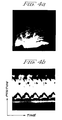
- Figure 4a is a 1 H axial image of a male volunteer in a prone position, so that the heart is fixed adjacent to the sternum.
- the image illustrates four different probe beams a-d, each of which is planned to follow the associated white path; beams a-c are planned to traverse the myocardial region from lower-left to upper- right, while beam d is planned to traverse the region from upper-left to lower-right.
- the gradient-refocussed echo is constructed into a profile along the axis of the selective 2D pulse with a 1DFT.
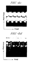
- Each profile is displayed as a row in a 256x256 image. Typically, 30 profiles are acquired each second.
- the repetition time, T R is 35 msec. and the echo time (t 4 -t 1 ) is 20 msec. in the examples illustrated.
- the axis of the selected cylinder is oriented by mixing various components of the gradients comprising the spiral. For example, to profile along the X axis, rotating gradients are applied in Gy and G z ; a profile along the Z axis uses G x and Gy gradient. Oblique directions require components along each axis to generate the oblique spiral in k-space. Displacement of the beam from gradient center by a distance is accomplished by modulating the rf excitation by the complex exponential
- the modulated waveforms are precomputed and stored in tables so that they may be recalled rapidly to adjust the beam placement.
- the beam is positioned so that the aliasing ring (with a sufficiently large diameter) does not intersect moving blood.
- Cardiac profiling data was taken continuously without gating and periodic undulations in the region of the heart will be seen, in Figures 4b-4d, to be consistent with the volunteer's heart rate.
- the beam is rotated to be normal to the septum to record the motion of the septum and cardiac chambers in Figure 4d; note the arrythmia shown here, illustrating that local irregularities in the cardiac cycle can be measured by the continuous recording technique of MR cardiac profiling (unlike current clinical MR cardiac cine which uses retrospective gating to average over many cycles).
- MR cardiac profiling unlike current clinical MR cardiac cine which uses retrospective gating to average over many cycles.
- the flow compensation gradient lobes 41 a and 41 b (Fig. 3) and prephasing lobe (41 and 42) may be omitted, and the data acquired as a free-induction decay, with half-Fourier reconstruction, to further reduce flow artifacts.
Landscapes
- Physics & Mathematics (AREA)
- General Physics & Mathematics (AREA)
- Engineering & Computer Science (AREA)
- Condensed Matter Physics & Semiconductors (AREA)
- Health & Medical Sciences (AREA)
- High Energy & Nuclear Physics (AREA)
- Cardiology (AREA)
- Pulmonology (AREA)
- General Health & Medical Sciences (AREA)
- Nuclear Medicine, Radiotherapy & Molecular Imaging (AREA)
- Radiology & Medical Imaging (AREA)
- Signal Processing (AREA)
- Power Engineering (AREA)
- Physiology (AREA)
- Biophysics (AREA)
- Life Sciences & Earth Sciences (AREA)
- Optics & Photonics (AREA)
- Spectroscopy & Molecular Physics (AREA)
- Magnetic Resonance Imaging Apparatus (AREA)
Applications Claiming Priority (2)
| Application Number | Priority Date | Filing Date | Title |
|---|---|---|---|
| US07/392,315 US4995394A (en) | 1989-08-11 | 1989-08-11 | Fast NMR cardiac profile imaging |
| US392315 | 1996-02-22 |
Publications (2)
| Publication Number | Publication Date |
|---|---|
| EP0412819A2 true EP0412819A2 (de) | 1991-02-13 |
| EP0412819A3 EP0412819A3 (en) | 1991-07-24 |
Family
ID=23550105
Family Applications (1)
| Application Number | Title | Priority Date | Filing Date |
|---|---|---|---|
| EP19900308774 Withdrawn EP0412819A3 (en) | 1989-08-11 | 1990-08-09 | Nmr imaging |
Country Status (3)
| Country | Link |
|---|---|
| US (1) | US4995394A (de) |
| EP (1) | EP0412819A3 (de) |
| JP (1) | JPH03139327A (de) |
Cited By (8)
| Publication number | Priority date | Publication date | Assignee | Title |
|---|---|---|---|---|
| EP0488496A3 (en) * | 1990-11-26 | 1992-10-14 | Norbert J Pelc | Noninvasive myocardial motion analysis using phase contrast mri maps of myocardial velocity |
| EP0498570A3 (en) * | 1991-02-07 | 1993-04-14 | General Electric Company | Quantitative measurement of blood flow using cylindrically localized fourier velocity encoding |
| EP0571071A1 (de) * | 1992-04-28 | 1993-11-24 | Picker International, Inc. | Kinematographische Bilderzeugung mittels magnetischer Resonanz |
| EP0678754A1 (de) * | 1994-04-18 | 1995-10-25 | Picker International, Inc. | Verfahren und Gerät zur Bilderzeugung durch magnetische Resonanz |
| WO1996016340A1 (en) * | 1994-11-23 | 1996-05-30 | Philips Electronics N.V. | Method of and device for magnetic resonance imaging |
| US6404194B1 (en) * | 1994-08-05 | 2002-06-11 | The Board Of Trustees Of The Leland Stanford Junior University | Three dimensional magnetic resonance imaging using spiral trajectories in k-space |
| EP2484280A4 (de) * | 2009-09-29 | 2013-06-26 | Hitachi Medical Corp | Magnetresonanzbildgebungsvorrichtung und verfahren zur einstellung eines erregungsbereichs |
| CN119001811A (zh) * | 2024-10-23 | 2024-11-22 | 上海云鱼智能科技有限公司 | 一种无源核子剖面成像装置、测量方法及机器人 |
Families Citing this family (19)
| Publication number | Priority date | Publication date | Assignee | Title |
|---|---|---|---|---|
| US5192909A (en) * | 1991-01-07 | 1993-03-09 | General Electric Company | Spectroscopic localization using pinwheel nmr excitation pulses |
| US5318025A (en) * | 1992-04-01 | 1994-06-07 | General Electric Company | Tracking system to monitor the position and orientation of a device using multiplexed magnetic resonance detection |
| US5307808A (en) * | 1992-04-01 | 1994-05-03 | General Electric Company | Tracking system and pulse sequences to monitor the position of a device using magnetic resonance |
| US5271400A (en) * | 1992-04-01 | 1993-12-21 | General Electric Company | Tracking system to monitor the position and orientation of a device using magnetic resonance detection of a sample contained within the device |
| US5353795A (en) * | 1992-12-10 | 1994-10-11 | General Electric Company | Tracking system to monitor the position of a device using multiplexed magnetic resonance detection |
| JPH10505780A (ja) * | 1995-07-20 | 1998-06-09 | フィリップス エレクトロニクス エヌ ベー | 磁気共鳴を利用して身体の湾曲部分を画像化する方法及び装置 |
| US5602891A (en) * | 1995-11-13 | 1997-02-11 | Beth Israel | Imaging apparatus and method with compensation for object motion |
| US5903664A (en) * | 1996-11-01 | 1999-05-11 | General Electric Company | Fast segmentation of cardiac images |
| US6032069A (en) * | 1998-05-01 | 2000-02-29 | Uab Research Foundation | Physiological triggering device for high-field magnetic-resonance instrumentation |
| US6452391B1 (en) * | 1999-06-11 | 2002-09-17 | General Electric Company | Quiet mode magnetic resonance imaging system and method |
| US6288541B1 (en) | 1999-08-23 | 2001-09-11 | General Electric Company | MRI measurement of blood vessel wall compliance |
| US6801800B2 (en) * | 1999-11-29 | 2004-10-05 | Kabushiki Kaisha Toshiba | MR imaging using ECG-prep scan |
| JP4632535B2 (ja) | 2000-12-27 | 2011-02-16 | 株式会社東芝 | Mri装置 |
| US7157908B1 (en) | 2002-12-10 | 2007-01-02 | Fonar Corporation | Magnetic resonance imaging using bessel functions |
| US7307419B2 (en) * | 2004-12-20 | 2007-12-11 | General Electric Company | Method and system for spatial-spectral excitation by parallel RF transmission |
| US7750632B2 (en) * | 2007-03-22 | 2010-07-06 | University Of Pittsburgh - Of The Commonwealth System Of Higher Education | Method for producing a magnetic resonance image of an object having a short T2 relaxation time |
| US9995810B2 (en) * | 2008-06-20 | 2018-06-12 | Weinberg Medical Physics Inc | Apparatus and method for decreasing bio-effects of magnetic gradient field gradients |
| US10172521B2 (en) | 2013-07-08 | 2019-01-08 | General Electric Company | Systems and methods for tracking imaging attenuators |
| US9594144B2 (en) | 2014-04-23 | 2017-03-14 | General Electric Company | Low-noise magnetic resonance imaging using low harmonic pulse sequences |
Family Cites Families (4)
| Publication number | Priority date | Publication date | Assignee | Title |
|---|---|---|---|---|
| US4516582A (en) * | 1983-05-02 | 1985-05-14 | General Electric Company | NMR blood flow imaging |
| US4739766A (en) * | 1986-08-18 | 1988-04-26 | Duke University | NMR blood vessel imaging method and apparatus |
| US4812760A (en) * | 1987-07-27 | 1989-03-14 | General Electric Company | Multi-dimensional selective NMR excitation with a single RF pulse |
| US4857846A (en) * | 1988-03-31 | 1989-08-15 | The Regents Of The University Of California | Rapid MRI using multiple receivers producing multiply phase-encoded data derived from a single NMR response |
-
1989
- 1989-08-11 US US07/392,315 patent/US4995394A/en not_active Expired - Lifetime
-
1990
- 1990-08-03 JP JP2205350A patent/JPH03139327A/ja active Granted
- 1990-08-09 EP EP19900308774 patent/EP0412819A3/en not_active Withdrawn
Non-Patent Citations (6)
| Title |
|---|
| HEWLETT-PACKARD JOURNAL, vol. 37, no. 6, June 1986, pages 20-25, Amstelveen, NL; R.G. O'CONNELL, Jr.: "The role of doppler ultrasound in cardiac diagnosis" * |
| IEEE TRANSACTIONS ON MEDICAL IMAGING, vol. MI-5, no. 3, September 1986, pages 140-151, IEEE, New York, US; D.G. NISHIMURA et al.: "Magnetic resonance angiography" * |
| JOURNAL OF MAGNETIC RESONANCE, vol. 81, no. 1, January 1989, pages 43-56, Duluth, MN, US; J. PAULY et al.: "A k-space analysis of small-tip-angle excitation" * |
| JOURNAL OF MAGNETIC RESONANCE, vol. 82, no. 3, May 1989, pages 571-587, Duluth, MN, US; J. PAULY et al.: "A linear class of large-tip-angle selective excitation pulses" * |
| MAGNETIC RESONANCE IN MEDICINE, vol. 6, no. 3, March 1988, pages 275-286, Duluth, MN, US; C.L. DUMOULIN et al.: "Time-resolved magnetic resonance angiography" * |
| MEDICAL PHYSICS, vol. 13, no. 5, September/October 1986, pages 648-657, New York, NY, US; M.A. BERNSTEIN et al.: "Pulse sequence generated oblique magnetic resonance imaging: Applications to cardiac imaging" * |
Cited By (11)
| Publication number | Priority date | Publication date | Assignee | Title |
|---|---|---|---|---|
| EP0488496A3 (en) * | 1990-11-26 | 1992-10-14 | Norbert J Pelc | Noninvasive myocardial motion analysis using phase contrast mri maps of myocardial velocity |
| EP0498570A3 (en) * | 1991-02-07 | 1993-04-14 | General Electric Company | Quantitative measurement of blood flow using cylindrically localized fourier velocity encoding |
| US5329925A (en) * | 1991-11-14 | 1994-07-19 | Picker International, Inc. | Reduced scan time cardiac gated magnetic resonance cine and flow imaging |
| EP0571071A1 (de) * | 1992-04-28 | 1993-11-24 | Picker International, Inc. | Kinematographische Bilderzeugung mittels magnetischer Resonanz |
| EP0678754A1 (de) * | 1994-04-18 | 1995-10-25 | Picker International, Inc. | Verfahren und Gerät zur Bilderzeugung durch magnetische Resonanz |
| US5532595A (en) * | 1994-04-18 | 1996-07-02 | Picker International, Inc. | Three-dimensional spiral echo volume imaging |
| US6404194B1 (en) * | 1994-08-05 | 2002-06-11 | The Board Of Trustees Of The Leland Stanford Junior University | Three dimensional magnetic resonance imaging using spiral trajectories in k-space |
| WO1996016340A1 (en) * | 1994-11-23 | 1996-05-30 | Philips Electronics N.V. | Method of and device for magnetic resonance imaging |
| EP2484280A4 (de) * | 2009-09-29 | 2013-06-26 | Hitachi Medical Corp | Magnetresonanzbildgebungsvorrichtung und verfahren zur einstellung eines erregungsbereichs |
| US9594135B2 (en) | 2009-09-29 | 2017-03-14 | Hitachi, Ltd. | Magnetic resonance imaging apparatus and method for adjusting excitation region |
| CN119001811A (zh) * | 2024-10-23 | 2024-11-22 | 上海云鱼智能科技有限公司 | 一种无源核子剖面成像装置、测量方法及机器人 |
Also Published As
| Publication number | Publication date |
|---|---|
| JPH0433454B2 (de) | 1992-06-03 |
| JPH03139327A (ja) | 1991-06-13 |
| US4995394A (en) | 1991-02-26 |
| EP0412819A3 (en) | 1991-07-24 |
Similar Documents
| Publication | Publication Date | Title |
|---|---|---|
| US4995394A (en) | Fast NMR cardiac profile imaging | |
| JP3440112B2 (ja) | 器具の位置を監視するための磁気共鳴追跡システム | |
| US6377048B1 (en) | Magnetic resonance imaging device for operation in external static magnetic fields | |
| US5810728A (en) | MR imaging method and apparatus for guiding a catheter | |
| US4521733A (en) | NMR Imaging of the transverse relaxation time using multiple spin echo sequences | |
| EP1444530B1 (de) | Dreidimensionale phasenkontrastmagnetresonanzabbildung mit verschachtelten projektions-rekonstruktions-daten | |
| US6275722B1 (en) | Methods and apparatus for magnetic resonance imaging with RF coil sweeping | |
| US7511494B2 (en) | Method for measuring the microarchitecture of complex tissue with MRI | |
| US5447156A (en) | Magnetic resonance (MR) active invasive devices for the generation of selective MR angiograms | |
| JP3440114B2 (ja) | 多重磁気共鳴検出を使用して器具の位置および方向を監視するための追跡システム | |
| US5604435A (en) | Spiral scanning method for monitoring physiological changes | |
| EP0349231A2 (de) | Magnetische Kernspinresonanz für Durchfluss-Kontrast-Angiographie | |
| EP0471501A2 (de) | Verfahren und Gerät für die Kernspinresonanz- Angiographie | |
| US6876198B2 (en) | Magnetic resonance imaging system | |
| EP0235758A2 (de) | Angiographisches Verfahren mittels magnetischer Kernresonanz und Gerät zur Durchführung dieses Verfahrens | |
| JPH0685770B2 (ja) | データアレイを区分する方法及び装置 | |
| US20100256478A1 (en) | Systems and methods for phase encode placement | |
| US4953554A (en) | Magnetic resonance imaging method | |
| JP2007534354A (ja) | 脂肪抑制を用いる血管の等方性画像形成 | |
| US4567440A (en) | Vivo P-31 NMR imaging of phosphorus metabolites | |
| US6259940B1 (en) | Method of performing magnetic resonance angiography using two-dimensional imaging and de-rated gradients | |
| JPH0616766B2 (ja) | Nmrイメージング装置を使用した高速流れ測定方式 | |
| JP3656654B2 (ja) | 移動流体の速度および加速度分布の同時検出方法 | |
| EP0042255B1 (de) | Verfahren und Vorrichtung für die kernmagnetische Resonanz | |
| JP3656652B2 (ja) | 移動流体の複数の運動成分の同時検出方法 |
Legal Events
| Date | Code | Title | Description |
|---|---|---|---|
| PUAI | Public reference made under article 153(3) epc to a published international application that has entered the european phase |
Free format text: ORIGINAL CODE: 0009012 |
|
| AK | Designated contracting states |
Kind code of ref document: A2 Designated state(s): DE FR GB NL |
|
| PUAL | Search report despatched |
Free format text: ORIGINAL CODE: 0009013 |
|
| AK | Designated contracting states |
Kind code of ref document: A3 Designated state(s): DE FR GB NL |
|
| 17P | Request for examination filed |
Effective date: 19911216 |
|
| 17Q | First examination report despatched |
Effective date: 19941019 |
|
| STAA | Information on the status of an ep patent application or granted ep patent |
Free format text: STATUS: THE APPLICATION IS DEEMED TO BE WITHDRAWN |
|
| 18D | Application deemed to be withdrawn |
Effective date: 19961002 |