EP0412825B1 - Compensateur de signaux - Google Patents
Compensateur de signaux Download PDFInfo
- Publication number
- EP0412825B1 EP0412825B1 EP90308795A EP90308795A EP0412825B1 EP 0412825 B1 EP0412825 B1 EP 0412825B1 EP 90308795 A EP90308795 A EP 90308795A EP 90308795 A EP90308795 A EP 90308795A EP 0412825 B1 EP0412825 B1 EP 0412825B1
- Authority
- EP
- European Patent Office
- Prior art keywords
- signals
- cos
- input signals
- signal
- sin
- Prior art date
- Legal status (The legal status is an assumption and is not a legal conclusion. Google has not performed a legal analysis and makes no representation as to the accuracy of the status listed.)
- Expired - Lifetime
Links
Images


Classifications
-
- G—PHYSICS
- G08—SIGNALLING
- G08C—TRANSMISSION SYSTEMS FOR MEASURED VALUES, CONTROL OR SIMILAR SIGNALS
- G08C19/00—Electric signal transmission systems
- G08C19/38—Electric signal transmission systems using dynamo-electric devices
- G08C19/46—Electric signal transmission systems using dynamo-electric devices of which both rotor and stator carry windings
-
- G—PHYSICS
- G06—COMPUTING OR CALCULATING; COUNTING
- G06F—ELECTRIC DIGITAL DATA PROCESSING
- G06F7/00—Methods or arrangements for processing data by operating upon the order or content of the data handled
- G06F7/38—Methods or arrangements for performing computations using exclusively denominational number representation, e.g. using binary, ternary, decimal representation
- G06F7/48—Methods or arrangements for performing computations using exclusively denominational number representation, e.g. using binary, ternary, decimal representation using non-contact-making devices, e.g. tube, solid state device; using unspecified devices
- G06F7/544—Methods or arrangements for performing computations using exclusively denominational number representation, e.g. using binary, ternary, decimal representation using non-contact-making devices, e.g. tube, solid state device; using unspecified devices for evaluating functions by calculation
- G06F7/548—Trigonometric functions; Co-ordinate transformations
Definitions
- This invention is concerned with a measurement system comprising a measuring instrument for sensing the angular position ( ⁇ ) of a rotatable part and providing input signals x and y that ideally vary as cos ⁇ and sin ⁇ respectively but are liable to error.
- the invention is more particularly concerned with the reduction of errors in the signals x and y due to known error factors.
- the invention relates to both a measurement system and to a method for compensating errors in the sensing of an angular position ( ⁇ ) of a rotatable part using a measuring instrument providing the input signals x and y mentioned above.
- the error components in the signals x and y may also be referred to as noise or distortion components.
- a particular application of this invention is to the high-resolution measurement of position or angle for resolver and encoder signals involving an arc-tangent operation on the signals x and y.
- Resolvers and encoders are widely used to measure rotational angles. Resolvers output one or more signal cycles approximated by sin ⁇ and cos ⁇ for each revolution, and these are processed (arc-tangent operation) to produce a signal equivalent to ⁇ . Encoders output several dozen to several thousand signal cycles approximated by sin ⁇ and cos ⁇ for each revolution, and in most cases the wave numbers of these signals are used to count the amount of rotation. Where higher resolution is required, arc-tangent operation is used to yield ⁇ just as for resolvers.
- U.S. patent 4,458,322 discloses a servo system which includes a measurement of the angular position of a motor driven shaft. The measurement is made by an optical encoder to produce a pair of quadrature output signals. The signals are digitized, and subject to correction for offset and amplitude errors. The correction procedure includes peak detection of the digitized quadrature signals.
- a measurement system comprising a measuring instrument for sensing the angular position ⁇ of a rotatable part, said instrument providing input signals x and y that ideally vary as cos ⁇ and sin ⁇ respectively but are liable to error, and a signal compensator responsive to said input signals x and y to generate therefrom an output signal representing the angular position ⁇ , said input signal compensator including means to reduce errors in said signals x and y resulting from at least one of the following error factors, namely amplitude difference, zero point variation, cross-talk, second-order harmonic and third-order harmonic respectively, characterized in that said error reducing means comprises:
- signal correcting means responsive to said input signals x and y to process said input signals x and y with the aid of stored coefficients and to generate corrected signals x and y respectively;
- detection means responsive to said corrected signals x and y to detect at least one of a set of the maximum values d 0 , d 1 , d 2 , d 3 , d 4 , d 5 , d 6 and d 7 pertaining to the values x, x+y, y, y-x, -x, -(x+y), -y and x-y respectively of said corrected signals x and y;
- a method for compensating errors in the sensing of an angular position ⁇ of a rotatable part which comprises using a measuring instrument to sense the angular position ⁇ of a rotatable part and to provide input signals x and y that ideally vary as cos ⁇ and sin ⁇ respectively but are liable to error, and employing a signal compensation procedure responsive to said input signals x and y to generate therefrom an output signal representing the angular position ⁇ , said signal compensation procedure including steps to reduce errors in said input signals x and y resulting from at least one of the following error factors, namely amplitude difference, zero point variation, cross-talk, second-order harmonic and third-order harmonic respectively, characterized in that the error-reducing steps comprise:
- correction is made only for amplitude and zero point fluctuation in the input signals x and y.
- the maximum values detected arc d 0 , d 2 , d 4 , and d 6 .
- correction is made only for cross-talk between, and zero point fluctuations in, the input signals x and y.
- the maximum values detected in this instance are d 1 , d 3 , d 5 , and d 7 .
- the output signal generating means is operable to generate the output signal representing the angular position ( ⁇ ) from the corrected signals x and y by an arc-tangent operation.
- the detection means operates to obtain a detected maximum value of a given kind, i.e. d 0 to d 7 , by an exponential smoothing procedure operating on successive detected maximum values of the given kind and, preferably, such successive detected maximum values are detected at values of ⁇ that are separated by ⁇ /4.
- G, g, k, b x , b y , h, z x and z y are respective coefficients corresponding to the size of respective error factors consisting of average amplitude, amplitude difference between the two signals x and y, cross-talk, second-order harmonic included in the signal x, second-order harmonic included in the signal y, third-order harmonic included in both signals x and y at the same amount respectively, zero point of the signal x and zero point of the signal y.
- the signal compensator is connected to the output of a measuring apparatus such as a resolver, an encoder and so on through amplifiers and A/D converters (for signals x and y).
- Coefficient g represents the amplitude difference between x and y, and if the gain of their signal amplifiers differs a non-zero value will result. Amplifier gain is generally determined by the resistance, but this itself contains error making precise adjustment difficult. Further, temperature causes change in resistance, and therefore when the amount of change on the signal x side differs from that on the signal y side, second terms appear in expressions (1) and (2).
- Coefficient k indicates cross-talk, and is a non-zero value when phase difference between x and y is not precisely ⁇ /2. This occurs when the signal lines approach and cause signal mixing between them, or when the encoder scale pitch is different from the value demanded by the detector pitch.
- Coefficients b x and b y indicate the non-linearity of the amplifiers, and are non-zero values if their non-linearity cannot be neglected.
- the amount of non-linearity is dependent on the amplifier, and therefore the size of the fourth terms may differ between x and y.
- Coefficient h represents the amount of third-order harmonic present, and will be a non-zero value when the source signal (unprocessed signal) from the detector is distorted from a sine wave. Distortion of the signal from the sine wave means harmonic content of a variety of orders and phases. However, for measurement instruments such as resolvers and encoders the detector is generally designed to be symmetric with respect to the signal sign and direction of rotation, so that harmonics of even orders and harmonics of odd orders with phases different from the fundamental wave will be suppressed. In these measurement devices the magnetic field distribution is unified by the air gap to reduce high-order harmonics, leaving third-order harmonics dominant. This means that the distortion of the source signal from the detector can be approximated by the fifth term.
- z x and z y express the zero points of the signals, and will be non-zero values when the zero point fluctuation or adjustment error cannot be ignored.
- Amplifiers exhibit a phenomenon called drift, where temperature change and other factors can cause the zero point to vary. In many cases the zero point can be adjusted with a variable resistance (trimmer), but precise adjustment is difficult and temperature change will cause variation in resistance as well.
- the sixth term appears in expressions (1) and (2).
- Input signals x and y are monitored to automatically determine any of the above coefficients that cannot be ignored and to compensate accordingly. Where all coefficients are determined the procedure is as follows:
- the maximum values for x, x+y, y, -x+y, -x, -x-y, -y and x-y are determined respectively as d 0 , d 1 , d 2 , d 3 , d 4 , d 5 , d 6 and d 7 .
- d i corresponds to the maximum value for the general expression xcosi( ⁇ /4)+ysini( ⁇ /4).
- This is equivalent to ⁇ /4 radii for the Lissajous' curve obtained when the x and y signals are plotted orthogonally.
- i odd number d i
- the value in the above general expression can be treated as times ⁇ 2. This is because the expression itself can be simplified, reducing the operations required. This treatment is employed in the actual operation.
- d 0 through d 7 represent the maximum values for x, x+y, y, -x+y, -x, -x-y, -y and x-y, but as the encoder or resolver shaft cannot be expected to rotate at a fixed speed simple peak detection methods cannot be used. Since x and y are signals approximating cos ⁇ and sin ⁇ , it is possible to detect these values by sampling x, x+y, etc., where ⁇ is i ⁇ /4.
- the value ⁇ used here is yielded through an arc-tangent operation, but the value which has not subjected to arc-tangent operation may be used in some cases.
- ⁇ when ⁇ is close to zero, ⁇ can be approximated by sin ⁇ , and when y or its compensated absolute value is small, it is sufficient to sample d 0 when x is positive or d 4 when x is negative.
- Expressions (1) and (2) take all possible factors for error into account, but in fact in most cases it is sufficient to compensate only for amplitude and zero point variation. In these cases, coefficients k, b x , b y and h can be replaced by 0, as described below.
- the method described above consists of detection of the amount of the error factors included in the source signal, and compensation by subtracting these from the source signal. If the size of the error factor is known, it is possible to estimate the size of the error when a signal with that error component is arc-tangent processed, allowing compensation of the operation results. This method is described below:
- the source signal can be represented by vector notation as follows:
- r ⁇
- Each vector can be expressed as indicated below when components are given: Although we need angle ⁇ between vector
- Either of the two compensation methods described above may be used individually, or they may be used specifically to match different error factors.
- the correction of the effects of third-order harmonics at the source signal requires more calculation, and compensation of angle error may therefore be more efficient, but direct compensation of other errors at the source signal is generally most efficient.
- Application requires selection of the optimum method, taking into account the amount of calculation required and remembering that accurate compensation is not possible where error is large because compensation is implemented through approximation.
- Fig. 1 shows a block diagram of the one example of the signal compensator, which comprises an error factor eliminating means 1, an arc-tangent operating means 2, a maximum value detecting means 3, a coefficients calculating means 4 and control means 5.
- the error factor eliminating means 1 receives the input signals x and y, approximates the signals in accordance with the above-mentioned expressions, and compensates the signals using the coefficients supplied from the coefficients calculating means 4.
- the arc-tangent operating means 2 receive the compensated cos ⁇ and sin ⁇ signals and calculates ⁇ by arc-tangent operation.
- the maximum value detecting means 3 detects the maximum values of x, x+y, etc., using the method mentioned above.
- the coefficients calculating means 4 calculates the coefficients in accordance with the above-mentioned expressions providing the relationships between the maximum values detected by the maximum value detecting means 3 and the respective size of the error factors.
- the output of the coefficients calculating means 4 is fed back to the error factor eliminating means 1 for compensation.
- the control means 5 controls the operations of the means 1 through 4.
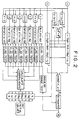
- Fig. 2 indicates the data flow of the signal compensator of Fig.1
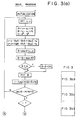
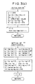
- Fig. 3 indicates the processing flow of a microprocessor handling the signal processing described in this invention, giving C language function names and operators.
- the signals x and y are read from A/D converters or other devices, and the zero point and amplitude used to determine cos ⁇ and sin ⁇ .
- the double angle formula is then used to determine cos2 ⁇ .
- the values determined above and the coefficients representing the amounts of included error are used to compensate the signals, and ⁇ is determined through arc-tangent operation.
- the arc-tangent operation here is iterated for the angular range of vector (x,y) from - ⁇ to ⁇ , just as with the C language function atan2. This function actually implemented by case branching and table reference through the signs of both signals and the absolute value size functions.
- Next error due to third harmonic is predicted, compensated for, and the result output as a value from 0 to 2 ⁇ .
- the value of ⁇ is used to judge if any maximum values need to be compensated.
- Maximum value compensation is carried out alternately (using a flag such as f04) for the values where ⁇ is different by ⁇ from each other.
- Exponential smoothing is used in compensation to weight the latest value with 1/256 weighing (in this example).
- the alternating compensation flag and the flag indicating that all maximum values have been reset are set.
- the coefficients are recalculated if all have been updated.
- Fig. 3 follows C language expression to make comprehension easier, but Assembler description is actually used to enhance execution speed. Processing flow is simplified in this figure, but in fact actual processing consists of multiple interrupt routines operating together to minimize the time from input of the signal to output of ⁇ .
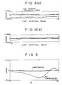
- Fig. 4 indicates the change in error in an encoder after power is turned on, for one rotation in the positive direction.
- Figs. 4(a) and 4(b) indicate the error for the first half-rotation and the second half-rotation, at ⁇ 1/10000 rotations full-scale, respectively.
- one rotation of the encoder shaft corresponds to 512 cycles of sin ⁇ and cos ⁇ .
- the arc-tangent error reduces with the rotation of the shaft.
- Fig. 5 also plots the arc-tangent operation error before and after compensation, with ordinate of ⁇ 1/10000 rotations and abscissa of ⁇ form 0 to 2 ⁇ . From these figures it is clear that error rapidly decreases with rotation after the power is turned on.
Landscapes
- Physics & Mathematics (AREA)
- General Physics & Mathematics (AREA)
- Engineering & Computer Science (AREA)
- Pure & Applied Mathematics (AREA)
- Mathematical Optimization (AREA)
- Mathematical Analysis (AREA)
- Computational Mathematics (AREA)
- Theoretical Computer Science (AREA)
- Mathematical Physics (AREA)
- Computing Systems (AREA)
- General Engineering & Computer Science (AREA)
- Transmission And Conversion Of Sensor Element Output (AREA)
- Indication And Recording Devices For Special Purposes And Tariff Metering Devices (AREA)
Claims (9)
- Système de mesure comprenant un instrument de mesure pour détecter la position angulaire θ d'une pièce rotative, ledit instrument fournissant des signaux d'entrée x et y qui varient idéalement comme cos θ et sin θ respectivement, mais sont susceptibles d'erreur, et un compensateur de signaux répondant auxdits signaux d'entrée x et y pour produire à partir d'eux un signal de sortie représentant la position angulaire θ, ledit compensateur de signaux d'entrée comprenant un moyen de réduction des erreurs dans lesdits signaux x et y résultant d'au moins l'un des facteurs d'erreur suivants, à savoir : la différence d'amplitude, la variation du point zéro, la diaphonie, l'harmonique de second ordre et l'harmonique de troisième ordre, respectivement, caractérisé en ce que ledit moyen de réduction des erreurs comprend :un moyen de correction des signaux (1) répondant auxdits signaux d'entrée x et y pour traiter lesdits signaux d'entrée x et y avec l'aide de coefficients en mémoire et pour générer des signaux corrigés x et y respectivement ;un moyen de détection (3) répondant auxdits signaux corrigés x et y pour détecter au moins l'une d'un ensemble des valeurs maximales d0, d1, d2, d3, d4, d5, d6 et d7 appartenant aux valeurs x, x+y, y, y-x, -x, -(x+y), -y et x-y, respectivement, desdits signaux corrigés x et y;un moyen générateur de coefficients (4) répondant à ladite ou auxdites valeurs maximales pour générer lesdits coefficients à partir d'elles pour qu'ils soient mis en mémoire et utilisés par ledit moyen de correction de signaux (1) dans le traitement des signaux d'entrée x et y,un moyen générateur de signaux (2) répondant auxdits signaux corrigés x et y pour générer un signal de sortie représentant ladite position angulaire θ; etledit moyen de détection (3) pouvant être utilisé pour détecter ladite ou lesdites valeurs maximales di aux valeurs de θ = iπ/4 ± δ où δ est un angle dont la valeur du cosinus peut être approximativement équivalente à 1 en pratique et i est un nombre entier entre 0 et 7.
- Système de mesure selon la Revendication 1 dans lequel la correction n'est faite que pour l'amplitude et la fluctuation du point zéro dans les signaux d'entrée x et y, les signaux d'entrée x et y étant représentés par les expressions


- Système de mesure selon la Revendication 1, dans lequel la correction n'est faite que pour la diaphonie entre lesdits signaux d'entrée x et y et les fluctuations du point zéro dans lesdits signaux, de telle sorte que les signaux d'entrée sont représentés par les expressions :


- Système de mesure selon la Revendication 1, dans lequel lesdits signaux d'entrée x et y sont représentés par les expressions :







- Système de mesure selon l'une quelconque des revendications précédentes, dans lequel ledit moyen de détection (3) sert à obtenir une valeur maximale détectée d'un type donné (d1 à d7) par une procédure de lissage exponentielle agissant sur des valeurs maximales détectées successives du type donné.
- Système de mesure selon la Revendication 5 dans lequel ledit moyen de détection (3) sert à exécuter ladite procédure de lissage exponentielle sur des valeurs maximales détectées successives d'un type donné qui sont détectées aux valeurs de θ qui sont séparées par π/4.
- Système de mesure selon l'une quelconque des revendications précédentes dans lequel ledit moyen de génération de signaux de sortie (2) peut être utilisé pour produire ledit signal de sortie représentant la position angulaire θ à partir des signaux corrigés x et y par une opération arc-tangente.
- Méthode de compensation des erreurs dans la détection d'une position angulaire θ d'une pièce rotative, qui comprend l'utilisation d'un instrument de mesure pour détecter la position angulaire θ d'une pièce pivotante et pour fournir des signaux d'entrée x et y qui varient idéalement comme cos θ et sin θ respectivement mais sont susceptibles d'erreur, et l'emploi d'une procédure de compensation de signaux répondant auxdits signaux x et y pour générer à partir d'eux un signal de sortie représentant la position angulaire θ, ladite procédure de compensation de signaux comprenant les étapes de réduction des erreurs dans lesdits signaux d'entrée x et y résultant d'au moins un des facteurs d'erreur suivants, à savoir : la différence d'amplitude, la variation du point zéro, la diaphonie, l'harmonique de second ordre et l'harmonique de troisième ordre, respectivement, caractérisée en ce que les étapes de réduction des erreurs comprennent :une étape de correction de signaux (1) répondant auxdits signaux d'entrée x et y pour traiter lesdits signaux d'entrée x et y avec l'aide de coefficients en mémoire et pour générer des signaux corrigés x et y respectivement;une étape de détection (3) répondant auxdits signaux corrigés x et y pour détecter au moins une d'un ensemble de valeurs maximales d0, d1, d2, d3, d4, d5, d6 et d7 appartenant aux valeurs x, x+y, y, y-x, -x, -(x+y), -y et x-y respectivement, desdits signaux corrigés x et y;une étape de génération de coefficients (4) répondant à ladite ou auxdites valeurs maximales pour générer à partir d'elles lesdits coefficients pour qu'ils soient mémorisés et utilisés dans ladite étape de correction de signaux (1) dans le traitement desdits signaux d'entrée x et y;une étape de génération de signaux de sortie (2) répondant auxdits signaux corrigés x et y pour générer un signal de sortie représentant ladite position angulaire θ; etladite étape de détection (3) comprenant la détection de ladite ou desdites valeurs maximales di aux valeurs de θ = iπ/4 + δ où δ est un angle dont la valeur du cosinus peut être approximativement égale à 1 en pratique et i est un nombre entier entre 0 et 7.
- Méthode de compensation des erreurs selon la Revendication 8, dans laquelle lesdits signaux d'entrée x et y sont représentés par les expressions :





Applications Claiming Priority (4)
| Application Number | Priority Date | Filing Date | Title |
|---|---|---|---|
| JP20582389A JP2790862B2 (ja) | 1989-08-10 | 1989-08-10 | 信号校正装置 |
| JP205824/89 | 1989-08-10 | ||
| JP205823/89 | 1989-08-10 | ||
| JP20582489A JP2790863B2 (ja) | 1989-08-10 | 1989-08-10 | 信号校正装置 |
Publications (3)
| Publication Number | Publication Date |
|---|---|
| EP0412825A2 EP0412825A2 (fr) | 1991-02-13 |
| EP0412825A3 EP0412825A3 (en) | 1992-08-05 |
| EP0412825B1 true EP0412825B1 (fr) | 1997-03-19 |
Family
ID=26515276
Family Applications (1)
| Application Number | Title | Priority Date | Filing Date |
|---|---|---|---|
| EP90308795A Expired - Lifetime EP0412825B1 (fr) | 1989-08-10 | 1990-08-09 | Compensateur de signaux |
Country Status (3)
| Country | Link |
|---|---|
| EP (1) | EP0412825B1 (fr) |
| KR (1) | KR100193293B1 (fr) |
| DE (1) | DE69030220T2 (fr) |
Cited By (1)
| Publication number | Priority date | Publication date | Assignee | Title |
|---|---|---|---|---|
| DE102018001851A1 (de) | 2017-03-24 | 2018-09-27 | SEW-EURODRlVE GmbH & Co. KG | Verfahren zur Bestimmung der Position, insbesondere Winkelstellung, einer zu Sensoren relativ bewegbar angeordneten Maßverkörperung, und Anordnung zur Durchführung eines solchen Verfahrens |
Families Citing this family (4)
| Publication number | Priority date | Publication date | Assignee | Title |
|---|---|---|---|---|
| JP4515120B2 (ja) * | 2004-03-12 | 2010-07-28 | ルネサスエレクトロニクス株式会社 | レゾルバディジタル角度変換装置および方法ならびにプログラム |
| JP4713123B2 (ja) * | 2004-10-13 | 2011-06-29 | 株式会社ミツトヨ | エンコーダ出力信号補正装置 |
| JP4768248B2 (ja) * | 2004-10-13 | 2011-09-07 | 株式会社ミツトヨ | エンコーダ出力信号補正装置及び方法 |
| US11021830B2 (en) | 2016-06-17 | 2021-06-01 | Lg Electronics Inc. | Method for controlling clothes treatment apparatus |
Family Cites Families (3)
| Publication number | Priority date | Publication date | Assignee | Title |
|---|---|---|---|---|
| FR2081247A1 (fr) * | 1970-03-23 | 1971-12-03 | Sfim | Convertisseur de tension analogique-numerique |
| US4227144A (en) * | 1979-01-16 | 1980-10-07 | The Singer Company | Error compensation of synchro control transmitters |
| US4458322A (en) * | 1981-06-19 | 1984-07-03 | Manhattan Engineering Co., Inc. | Control of page storage among three media using a single channel processor program and a page transfer bus |
-
1990
- 1990-08-09 DE DE69030220T patent/DE69030220T2/de not_active Expired - Fee Related
- 1990-08-09 EP EP90308795A patent/EP0412825B1/fr not_active Expired - Lifetime
- 1990-08-10 KR KR1019900012315A patent/KR100193293B1/ko not_active Expired - Fee Related
Cited By (1)
| Publication number | Priority date | Publication date | Assignee | Title |
|---|---|---|---|---|
| DE102018001851A1 (de) | 2017-03-24 | 2018-09-27 | SEW-EURODRlVE GmbH & Co. KG | Verfahren zur Bestimmung der Position, insbesondere Winkelstellung, einer zu Sensoren relativ bewegbar angeordneten Maßverkörperung, und Anordnung zur Durchführung eines solchen Verfahrens |
Also Published As
| Publication number | Publication date |
|---|---|
| EP0412825A2 (fr) | 1991-02-13 |
| EP0412825A3 (en) | 1992-08-05 |
| KR100193293B1 (ko) | 1999-06-15 |
| DE69030220D1 (de) | 1997-04-24 |
| KR910005179A (ko) | 1991-03-30 |
| DE69030220T2 (de) | 1997-10-16 |
Similar Documents
| Publication | Publication Date | Title |
|---|---|---|
| EP2827106B1 (fr) | Dispositif de détection d'angle | |
| US5463393A (en) | Method and apparatus for correcting errors in an amplitude encoded signal | |
| US5581488A (en) | Apparatus and method for compensating for noise in signals | |
| Masuda et al. | An automatic calibration system for angular encoders | |
| EP4012352B1 (fr) | Capteur de position à compensation de distorsion harmonique | |
| EP1850137A2 (fr) | Dispositif de mesure de position rotative | |
| EP3584541A1 (fr) | Dispositif et procédé d'initialisation | |
| JPS61162726A (ja) | 応力検出装置 | |
| US5933106A (en) | Encoder signal analysis system for high-resolution position measurement | |
| US6320524B1 (en) | R/D converter | |
| EP1058390B1 (fr) | Convertisseur R/N | |
| JP2839340B2 (ja) | 位置信号の校正装置 | |
| US20040194557A1 (en) | Torque sensor | |
| EP0412825A2 (fr) | Compensateur de signaux | |
| EP1647816A1 (fr) | Compensation numérique d'un détecteur sans contact de couple et d'angle pour un dispositif de direction | |
| US4890056A (en) | Method and apparatus for error correction of phase measurement signals | |
| JP2002524754A (ja) | 粗位置インジケータを使用する精密位置エンコーダ | |
| JP2839341B2 (ja) | 位置信号の校正装置 | |
| JPH06138199A (ja) | 飛しょう体の誘導制御装置 | |
| JP2790862B2 (ja) | 信号校正装置 | |
| EP4215878A1 (fr) | Système de capteur de position et procédé de détection d'une erreur d'un système de capteur de position | |
| JPH0410974B2 (fr) | ||
| US20020113571A1 (en) | Motor controller | |
| USH104H (en) | Digital resolver compensation technique | |
| JPH0358444B2 (fr) |
Legal Events
| Date | Code | Title | Description |
|---|---|---|---|
| PUAI | Public reference made under article 153(3) epc to a published international application that has entered the european phase |
Free format text: ORIGINAL CODE: 0009012 |
|
| 17P | Request for examination filed |
Effective date: 19901212 |
|
| AK | Designated contracting states |
Kind code of ref document: A2 Designated state(s): DE GB |
|
| PUAL | Search report despatched |
Free format text: ORIGINAL CODE: 0009013 |
|
| AK | Designated contracting states |
Kind code of ref document: A3 Designated state(s): DE GB |
|
| 17Q | First examination report despatched |
Effective date: 19950208 |
|
| RAP1 | Party data changed (applicant data changed or rights of an application transferred) |
Owner name: MITSUBISHI CHEMICAL CORPORATION |
|
| GRAG | Despatch of communication of intention to grant |
Free format text: ORIGINAL CODE: EPIDOS AGRA |
|
| GRAH | Despatch of communication of intention to grant a patent |
Free format text: ORIGINAL CODE: EPIDOS IGRA |
|
| GRAH | Despatch of communication of intention to grant a patent |
Free format text: ORIGINAL CODE: EPIDOS IGRA |
|
| GRAA | (expected) grant |
Free format text: ORIGINAL CODE: 0009210 |
|
| AK | Designated contracting states |
Kind code of ref document: B1 Designated state(s): DE GB |
|
| REF | Corresponds to: |
Ref document number: 69030220 Country of ref document: DE Date of ref document: 19970424 |
|
| PLBE | No opposition filed within time limit |
Free format text: ORIGINAL CODE: 0009261 |
|
| STAA | Information on the status of an ep patent application or granted ep patent |
Free format text: STATUS: NO OPPOSITION FILED WITHIN TIME LIMIT |
|
| 26N | No opposition filed | ||
| PGFP | Annual fee paid to national office [announced via postgrant information from national office to epo] |
Ref country code: GB Payment date: 19980731 Year of fee payment: 9 |
|
| PGFP | Annual fee paid to national office [announced via postgrant information from national office to epo] |
Ref country code: DE Payment date: 19980817 Year of fee payment: 9 |
|
| PG25 | Lapsed in a contracting state [announced via postgrant information from national office to epo] |
Ref country code: GB Free format text: LAPSE BECAUSE OF NON-PAYMENT OF DUE FEES Effective date: 19990809 |
|
| GBPC | Gb: european patent ceased through non-payment of renewal fee |
Effective date: 19990809 |
|
| PG25 | Lapsed in a contracting state [announced via postgrant information from national office to epo] |
Ref country code: DE Free format text: LAPSE BECAUSE OF NON-PAYMENT OF DUE FEES Effective date: 20000601 |