EP0412853A2 - Aktives Schwingungssteuergerät - Google Patents
Aktives Schwingungssteuergerät Download PDFInfo
- Publication number
- EP0412853A2 EP0412853A2 EP90308893A EP90308893A EP0412853A2 EP 0412853 A2 EP0412853 A2 EP 0412853A2 EP 90308893 A EP90308893 A EP 90308893A EP 90308893 A EP90308893 A EP 90308893A EP 0412853 A2 EP0412853 A2 EP 0412853A2
- Authority
- EP
- European Patent Office
- Prior art keywords
- vibration
- actuator
- digital filter
- adaptive
- type
- Prior art date
- Legal status (The legal status is an assumption and is not a legal conclusion. Google has not performed a legal analysis and makes no representation as to the accuracy of the status listed.)
- Granted
Links
Images











Classifications
-
- F—MECHANICAL ENGINEERING; LIGHTING; HEATING; WEAPONS; BLASTING
- F16—ENGINEERING ELEMENTS AND UNITS; GENERAL MEASURES FOR PRODUCING AND MAINTAINING EFFECTIVE FUNCTIONING OF MACHINES OR INSTALLATIONS; THERMAL INSULATION IN GENERAL
- F16F—SPRINGS; SHOCK-ABSORBERS; MEANS FOR DAMPING VIBRATION
- F16F15/00—Suppression of vibrations in systems; Means or arrangements for avoiding or reducing out-of-balance forces, e.g. due to motion
- F16F15/02—Suppression of vibrations of non-rotating, e.g. reciprocating systems; Suppression of vibrations of rotating systems by use of members not moving with the rotating systems
-
- B—PERFORMING OPERATIONS; TRANSPORTING
- B60—VEHICLES IN GENERAL
- B60G—VEHICLE SUSPENSION ARRANGEMENTS
- B60G17/00—Resilient suspensions having means for adjusting the spring or vibration-damper characteristics, for regulating the distance between a supporting surface and a sprung part of vehicle or for locking suspension during use to meet varying vehicular or surface conditions, e.g. due to speed or load
- B60G17/015—Resilient suspensions having means for adjusting the spring or vibration-damper characteristics, for regulating the distance between a supporting surface and a sprung part of vehicle or for locking suspension during use to meet varying vehicular or surface conditions, e.g. due to speed or load the regulating means comprising electric or electronic elements
- B60G17/018—Resilient suspensions having means for adjusting the spring or vibration-damper characteristics, for regulating the distance between a supporting surface and a sprung part of vehicle or for locking suspension during use to meet varying vehicular or surface conditions, e.g. due to speed or load the regulating means comprising electric or electronic elements characterised by the use of a specific signal treatment or control method
-
- G—PHYSICS
- G05—CONTROLLING; REGULATING
- G05D—SYSTEMS FOR CONTROLLING OR REGULATING NON-ELECTRIC VARIABLES
- G05D19/00—Control of mechanical oscillations, e.g. of amplitude, of frequency, of phase
- G05D19/02—Control of mechanical oscillations, e.g. of amplitude, of frequency, of phase characterised by the use of electric means
-
- B—PERFORMING OPERATIONS; TRANSPORTING
- B60—VEHICLES IN GENERAL
- B60G—VEHICLE SUSPENSION ARRANGEMENTS
- B60G2202/00—Indexing codes relating to the type of spring, damper or actuator
- B60G2202/40—Type of actuator
- B60G2202/42—Electric actuator
-
- B—PERFORMING OPERATIONS; TRANSPORTING
- B60—VEHICLES IN GENERAL
- B60G—VEHICLE SUSPENSION ARRANGEMENTS
- B60G2400/00—Indexing codes relating to detected, measured or calculated conditions or factors
- B60G2400/10—Acceleration; Deceleration
-
- B—PERFORMING OPERATIONS; TRANSPORTING
- B60—VEHICLES IN GENERAL
- B60G—VEHICLE SUSPENSION ARRANGEMENTS
- B60G2400/00—Indexing codes relating to detected, measured or calculated conditions or factors
- B60G2400/10—Acceleration; Deceleration
- B60G2400/102—Acceleration; Deceleration vertical
-
- B—PERFORMING OPERATIONS; TRANSPORTING
- B60—VEHICLES IN GENERAL
- B60G—VEHICLE SUSPENSION ARRANGEMENTS
- B60G2600/00—Indexing codes relating to particular elements, systems or processes used on suspension systems or suspension control systems
- B60G2600/02—Retarders, delaying means, dead zones, threshold values, cut-off frequency, timer interruption
-
- B—PERFORMING OPERATIONS; TRANSPORTING
- B60—VEHICLES IN GENERAL
- B60G—VEHICLE SUSPENSION ARRANGEMENTS
- B60G2600/00—Indexing codes relating to particular elements, systems or processes used on suspension systems or suspension control systems
- B60G2600/60—Signal noise suppression; Electronic filtering means
-
- B—PERFORMING OPERATIONS; TRANSPORTING
- B60—VEHICLES IN GENERAL
- B60G—VEHICLE SUSPENSION ARRANGEMENTS
- B60G2600/00—Indexing codes relating to particular elements, systems or processes used on suspension systems or suspension control systems
- B60G2600/60—Signal noise suppression; Electronic filtering means
- B60G2600/604—Signal noise suppression; Electronic filtering means low pass
-
- B—PERFORMING OPERATIONS; TRANSPORTING
- B60—VEHICLES IN GENERAL
- B60G—VEHICLE SUSPENSION ARRANGEMENTS
- B60G2600/00—Indexing codes relating to particular elements, systems or processes used on suspension systems or suspension control systems
- B60G2600/76—Digital systems
-
- B—PERFORMING OPERATIONS; TRANSPORTING
- B60—VEHICLES IN GENERAL
- B60G—VEHICLE SUSPENSION ARRANGEMENTS
- B60G2600/00—Indexing codes relating to particular elements, systems or processes used on suspension systems or suspension control systems
- B60G2600/90—Indexing codes relating to particular elements, systems or processes used on suspension systems or suspension control systems other signal treatment means
Definitions
- the present invention relates to an active-type vibration control apparatus which is capable of significantly reducing vibration transmitted from a movable base member to an object suspended on the base member in a vibration-isolating manner.
- an apparatus for actively controlling vibration of an object which is mounted on a vibratory base member with a vibration-isolating means therebetween, comprising: a vibration sensor secured to said object for detecting vibration thereof; an actuator secured to said object for applying an inverse vibration thereto; and a digital filter with an input connected to said vibration sensor and an output connected to said actuator, said digital filter being adapted to generate an output signal for controlling the actuator such that the vibration of said object is at least suppressed by the inverse vibration applied to the object by the actuator.
- the present invention thus provides an adaptive-type active vibration control apparatus for significantly reducing the vibration of various objects without being affected by resonance peak frequencies, which is particularly suitable when the object is applied with vibration over a wide frequency range, or with vibration of a random or periodic nature.
- the digital filter is an adaptive filter adapted to generate an output signal with a waveform having a correlation to a waveform of the object.
- the digital filter may be adapted to generate an output signal with a waveform which is proportional to, and of a sign opposite to that of the waveform of the object.
- the apparatus further comprises a second vibration sensor secured to the movable base member for detecting vibration thereof, the second vibration sensor being connected to a second input of the digital filter.
- the vibration sensor and the actuator may secured to selected one of the objects.
- the actuator may be arranged between said selected one of the objects and the vibratory base member.
- the actuator may be arranged between said selected one of the objects and another one of the objects.
- the apparatus includes an inverse vibration generating circuit (IVGC) 20 for generating an "inverse vibration" with a waveform which is proportional to, and of a sign opposite to that of the waveform of the vibration of the object 3.
- IVGC inverse vibration generating circuit
- the inverse vibration generated by the circuit 20 is applied to the object 3 via an actuator 12 secured thereto.
- the inverse vibration so applied to the object 3 interferes with the original vibration of the object 3 transmitted from the base member 1, so that the object 3 is caused to vibrate with a controlled, significantly reduced intensity.
- the inverse vibration for controlling the original vibration may be applied to the object 3 either directly or indirectly via elements which vibrates jointly with the object 3, or which vibrates with a waveform having a predetermined correlation to that of the object 3, such as a supporting table.
- the inverse vibration generating circuit 20 includes an adaptive digital filter 8 and a signal processor 17 for executing an adaptive algorithm.
- the digital filter 8 is supplied with a signal representing the vibration of the base member 1 as detected by a vibration sensor 4, and also with a signal representing the vibration of the object 3 as detected by another vibration sensor 13.
- the filter coefficients of the digital filter 8 are controlled by the signal processor 17 rapidly, so as to minimize the level of the signal detected by the vibration sensor 13.
- an actuator 12 is secured to the object 3 and controlled on a real-time basis by the digital filter 8 such that the actuator 12 applies to the object 3 an inverse vibration for effectively canceling the original vibration of the object 3.
- the vibration is controlled by the apparatus according to the present invention in that the vibrations of the base member 1 and the object 3 are respectively detected by the sensors 4 and 13 whose output signals are supplied to the digital filter 8 to generate a signal with a waveform inversely proportional to that of the original vibration of the object 3.
- This signal is supplied to the actuator 12 to apply to the object 3 a compensatory vibration which interferes with the original vibration of the object 3 to actively cancel the latter.
- the adaptive digital filter 8 included in the inverse vibration generating circuit 20 may be either FIR-type (Finite Impulse Response) filter or IIR-type (Infinite Impulse Response) filter.
- FIR-type adaptive digital filter is shown in Fig. 3, which is arranged to transform an input signal XK into a desired output signal YK, by properly determining the filter coefficients W OK , WiK, ... W LK .
- the adaptive digital filter 8 is combined with the signal processor 17 (Fig. 1) with an adaptive algorithm, the above- mentioned filter coefficients W OK , W IK , ... W LK are caused to vary in an adaptive manner following variation in the system or environmental parameters to converge into optimum filter coefficients.
- the adaptive algorithm may be executed for example by so-called LMS (Least Mean Square) method, SER (Sequential Regression) method, Newton method, steepest descent method, filtered-X algorithm, error scanning algorithm, etc.
- LMS Least Mean Square
- SER Simple Regression
- Newton method Newton method
- steepest descent method filtered-X algorithm
- error scanning algorithm etc.
- the LMS method is most suitable in efficiently executing the adaptive algorithm, whereby the convergence speed and the stability of the adaptive digital filter 8 can be adjusted in a well- balanced manner by adjusting the adaptive gain constant (u.).
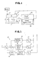
- the arrangement shown in Fig. 4 is constructed such that the vibration of the movable base member 1 as detected by the sensor 4 is converted into a signal which is supplied to a fixed-type inverse vibration generating circuit 25 (or to a fixed-type digital filter 50) such that the actuator 12 applies an inverse vibration to the object 3 to significantly reduce the vibration thereof.
- the fixed-type filter method shown in Fig. 4 also achieves an excellent reduction of the vibration in the same manner as the adaptive filter method shown in Fig. 2. Furthermore, switch-over into the fixed-type filter method is particularly advantageous for a pulsive input condition since it achieves a complete feed forward type control.
- the switch-over can be effected in opposite sense, i.e. from a fixed-type filter method to an adaptive filter method.
- the digital filter 8 functioning as a fixed-type digital filter with the fixed digital filter coefficients may be switched-over into an adaptive-type, so that an adaptive algorithm at the signal processor 17 takes place with the filter coefficients of the fixed-type control as the initial values, whereby the filter coefficients W oK , W 1K, ... WLK are rapidly varied to realize an optimum suppressed vibration state.
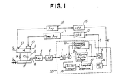
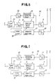
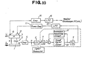
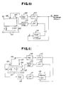
- Fig. 1 is a block diagram of a practical arrangement of the adaptive-type vibration controlling apparatus according to the present invention with a basic structure shown in Fig. 2, while Figs. 5-9 are block diagrams of various examples of the inverse vibration generating circuit 20 shown in Fig. 1. Furthermore, there is shown in Fig. 10 a block diagram of the vibration controlling circuit of Fig. 4 constructed by switching-over the inverse vibration generating circuit 20 of the adaptive-type vibration controlling apparatus of Fig. 2 into a fixed-type circuit.
- a fixed-type inverse vibration generating circuit 25 shown in Fig, 4 is formed for example by switching-over the adaptive digital filter 8 into a fixed-type filter mode
- This method is particularly advantageous in minimizing the convergence time.
- H - (T/D)
- Transfer function between points P and Q is measured by means of a frequency analyzer (FFT) or the like, by switching the actuator 12 into OFF state.
- FFT frequency analyzer
- Transfer function between points P and Q is measured by appropriately limiting the frequency range, and supplying an amplified random signal is from the point P to operate the actuator 12, while the amplifier 5 is separated from the point P and the fixed-type digital filter 50 is set into "all-pass" mode.
- the filter coefficients of the fixed-type digital filter 50 so determined can be used as initial values to switching into an adaptive digital filter method (Fig. 1).
- the adaptive-type inverse vibration generating circuit 20 may have an arrangement as shown in Figs. 5-9, other than that shown in Fig. 1. When, however, the circuit 20 is used by selectively switching into fixed mode and adaptive mode, it is preferable for the circuit to have the same arrangement in the two modes.
- the circuit In case of the switching mode ii) above, it is preferable for the circuit to have the same arrangement in the two digital filter modes.
- the vibration sensor 4 is to detect the vibration of the movable base member 1, i.e. the input signal to be applied to the adaptive-type inverse vibration generating circuit 20 or to the fixed-type inverse vibration generating circuit 25 which is obtained by switching the circuit 20 into the fixed-mode. By applying the detected signal to the digital filter 8 or 50, it is possible to generate an inverse vibration to be brought into interference with the vibration of the object 3.
- the signal detected by the sensor 4 may be one having a correlation to the vibration of the object 3 so that, besides the vibration of the movable base member 1, the signal representing the vibration of the object 3 itself may be used for this purpose.
- the sensors 4 and 13 may be of any type provided that it is capable of detecting the waveform of the vibration, such as a displacement sensor, a velocity sensor, an acceleration sensor, etc.
- the actuator 12 may be of any type provided that it is capable of applying an inverse vibration to the object 3 based on the output signal from the digital filter 8 or 20, such as an electromagnetic or piezo-electric actuator, an ultrasonic motor, a pneumatic or hydraulic actuator, an actuator using shape memory material, electrorheological fluid (ERF) or magnetic fluid, etc.
- an electromagnetic or piezo-electric actuator such as an ultrasonic motor, a pneumatic or hydraulic actuator, an actuator using shape memory material, electrorheological fluid (ERF) or magnetic fluid, etc.
- EMF electrorheological fluid
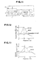
- Fig. 11 is a block diagram showing the basic arrangement of the vibration control circuit according to the invention, wherein the actuator 12 is arranged between the movable base member 1 and the object 3.
- This actuator 12 may also be used to apply an inverse vibration to the object, instead of inertia mass method shown in Fig. 1 which makes use of inertia force.
- the arrangement shown in Fig. 11 may include an actuator with a variable dynamic characteristic such as spring constant or damping force by using visco-electric fluid (ERF) or magnetic fluid, the dynamic characteristic can be varied so as to apply an optimum inverse vibration to the object 3.
- a variable dynamic characteristic such as spring constant or damping force by using visco-electric fluid (ERF) or magnetic fluid
- the inverse vibration application device includes vibration sensors 4, 13 for detecting the vibrations of the base member 1 and the object 3, respectively, amplifiers 5, 14 for amplifying the respective vibration signals, low-pass filters 6, 10, 15, analog-to- digital (A/D) converters 7, 16 for receiving the vibration signal, digital-to-analog (D/A) converter 9 for supplying the vibration signal, adaptive digital filter 8, signal processor 17 for executing the adaptive algorithm, resonance preventing circuit 19, delay circuit 18, vibration actuator 12 and its power amplifier 11.
- vibration sensors 4, 13 for detecting the vibrations of the base member 1 and the object 3, respectively, amplifiers 5, 14 for amplifying the respective vibration signals, low-pass filters 6, 10, 15, analog-to- digital (A/D) converters 7, 16 for receiving the vibration signal, digital-to-analog (D/A) converter 9 for supplying the vibration signal, adaptive digital filter 8, signal processor 17 for executing the adaptive algorithm, resonance preventing circuit 19, delay circuit 18, vibration actuator 12 and its power amplifier 11.
- the adaptive digital filter 8, signal processor 17, resonance preventing circuit 19, A/D converters 7, 16, and D/A converter 9 jointly constitute the above-mentioned inverse vibration generating circuit 20.
- the principle of the vibration control is that, as explained with reference to Fig. 2, the vibration of the movable base member 1 is detected by the sensor 4 whose output signal is passed through the adaptive digital filter 8 to generate a waveform which is capable of canceling the vibration transmitted through the path from the base member 1 to the object 3 via suspension 2.
- the signal representing such a waveform is amplified by the amplifier 11, whose output signal is applied to the actuator 12.
- the actuator 12 applies to the object 3 a vibration (inverse vibration) to reduce the vibration thereof.
- the vibration of the object 3 is detected by the sensor 13, and the filter coefficients of the adaptive digital filter 8 are varied at a high speed using the algorithm of the processor 17, so as to converge into optimum coefficients and thereby minimize the vibration of the object 3 detected by the sensor 13.
- the signal processor 17 is applied with the following two kinds of input signals.
- the input signal b) to the adaptive digital filter 8 has to be delayed by a predetermined delay time corresponding to the time required for the signal a) to pass through the path including the adaptive digital filter 8, D/A converter 9, low-pass filter 10, power amplifier 11, actuator 12, object 3, vibration sensor 13, amplifier 14, low-pass filter 15 and AID converter 16.
- the delay circuit 18 may be formed by a digital filter with a characteristic corresponding to the transfer characteristic of the above mentioned path, i.e. the path including the adaptive digital filter 8, D/A converter 9, low-pass filter 10, power amplifier 11, actuator 12, object 3, vibration sensor 13, amplifier 14, low-pass filter 15 and A/D converter 16.
- the delay circuit may be formed of appropriate delay element, or may be dispensed with particularly when there is no significant delay in the signal a) above.
- the resonance preventing circuit 19 flown in Fig. 1 is for preventing resonance of the vibration signal, and may have various arrangements as shown in Figs. 5-8.
- the resonance preventing circuit 19 may be formed of a digital filter in which filter coefficients are written based on a particular impulse response which, for example, is obtained by measuring the transfer characteristic of the path including the D/A converter 9, low-pass filter 10, power amplifier 11, actuator 12, object 3, suspension 2, movable base member 1, vibration sensor 4, amplifier 5, low-pass filter 6 and A/D converter 7.
- the vibration control apparatus may include an inverse vibration generating circuit 20 without the resonance preventing circuit 19.
- the low-pass filter (LPF) 6, 10 or 15 may be replaced by a band-pass filter having its filter characteristics determined in accordance with system parameters of the object to be controlled, as well as control conditions and other environmental conditions.
- Fig. 10 shows the arrangement of the vibration control apparatus wherein the adaptive-type filter mode shown in Fig. 1 has been switched into the fixed-type filter method.
- the fixed-type filter mode shown in Fig. 10 is advantageous in that, because of a complete feed-forward control, an excellent vibration control can be achieved even in case of a pulsive vibration. Furthermore, under a particular circumstance wherein the characteristics of the object 3, suspension 2, vibration sensors 4, 13, actuator 12, etc. are maintained substantially unchanged, the fixed-type filter mode shown in Fig. 10 serves to reduce the vibration as effectively as the adaptive-type filter mode shown in Fig. 1.
- the apparatus may be once again switched into the adaptive-type filter mode from the fixed-type filter mode, to vary the digital filter coefficients in accordance with the adaptive algorithm by the signal processor 17 and resume the optimum reduced vibration state.
- the present invention has been described with reference to a basic model for controlling one- dimensional vibration, though a plurality of such basic models may be combined to realize a more practical apparatus for controlling multi-dimensional vibration with multiple degrees of freedom.
- each apparatus includes vibration sensors and actuator oriented in a direction in which the vibration is to be reduced.
- the number of the apparatuses corresponds to the degrees of freedom requiring vibration reduction.
- Fig, 25 is a block diagram showing the arrangement of the apparatus for controlling two-dimensional vibration. It will be understood that, by providing a pair of the above-mentioned apparatuses, vibrations in two directions X and Y can be reduced simultaneously.
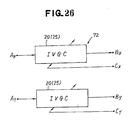
- the vibration control circuit 72 (Fig. 25) may be formed of either two adaptive-type inverse vibration generating circuits 20 (Fig. 2) or two fixed-type inverse vibration generating circuits 25 (Fig. 4), for reducing the vibrations in the directions X and Y, respectively.
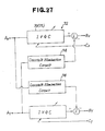
- the vibration control circuit 72 may include crosstalk elimination circuits 74 as shown in Fig. 27.
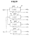
- the crosstalk elimination circuits 74 may be each formed, for example, of adaptive-type inverse vibration generating circuit 20 or fixed-type inverse vibration generating circuit 25, as shown in Figs. 28 and 29.
- the vibration control circuit 72 shown in Fig. 29 includes for one vibration direction each two sets of actuators 12, power amplifiers 11 and LPFs 10, i.e. each four sets as a whole.
- Fig. 30 is a block diagram showing the arrangement of the apparatus for controlling three-dimensional vibration. It will be appreciated that the control of the three-dimensional vibration can be effected essentially in the same manner as that for the two-dimensional vibration. In principle, by combining a set of three vibration control apparatuses, the three-dimensional vibration can be controlled simultaneously.
- the vibration control circuit 73 may be formed of either three adaptive-type inverse vibration generating circuits 20 (Fig. 2) or three fixed-type inverse vibration generating circuits 25 (Fig. 4), for reducing the vibrations in the directions X, Y and Z, respectively.
- Fig. 32 is a block diagram of a control circuit 73 shown in Fig. 30, which is suitable for eliminating the crosstalk components.
- the crosstalk eliminating circuit 75 shown in Fig. 32 may be formed of adaptive-type or fixed-type inverse vibration generating circuits 20 or 25 as shown in Fig. 33, similar to the example of Fig. 28.
- the invention makes it possible to simultaneously control multi-dimensional vibration by combining a plurality of vibration control apparatuses each shown in Figs. 1-11, the number of which depends upon the degree of freedom to be controlled.
- the number of the vibration control apparatuses and the control directions need not coincide with the number of degrees of freedom and the vibration direction, respectively, and may be determined without particular limitations provided that the vibration of the object can be sufficiently reduced. Generally, however, it is preferred to provide the vibration control apparatuses of the number which is same as or greater than the number of degrees of freedom so that they can be selectively operated whenever necessary.
- the vibration control apparatus is for actively canceling the vibration of the object 3 transmitted from the base member 1 via suspension 2, by applying a controlled inverse vibration to the object 3 by means of the actuator 12, and is arranged such that the inverse vibration is subjected to a successive correction based on a signal representing the vibration of the object 3 itself or the vibration correlated to the latter, to maintain the optimum reduced vibration state.
- the apparatus is thus featured by an active and adaptive control for reducing the vibration of the object 3.
- Fig. 12 is a graph showing the response ratios of the object 3 with reference to the movable base member 1 under condition (A) in which the vibration control apparatus with the arrangement shown in Fig. 1 is switched into OFF state so as not to effect the control, and condition (B) in which the vibration control apparatus is switched into ON state to effect the control.
- Fig. 13 is a graph showing the result of measurement of the vibration acceleration level of the object 3 corresponding to the conditions (A) and (B) in Fig. 12. While the results shown in Figs. 12 and 13 have been obtained by applying a random vibration input to the base member 1, it has been confirmed that similarly effective vibration reduction can be achieved also in the case of periodical vibration and vibration with variable period.
- the present invention makes it possible to realize a resonance-free anti-vibration suspension device with the response ratio of 1.0 or less, as shown in Fig. 12, and to significantly reduce the vibration acceleration level of the object 3, e.g. by approximately 20dB at 5 Hz, thereby achieving a remarkable vibration reduction.
- Fig. 14 is a graph showing the vibration acceleration amplitude of the object 3 under condition (A) in which the vibration control apparatus with the arrangement shown in Fig. 1 is switched into OFF state, and condition (B) in which the vibration control apparatus is switched into ON state and the filter coefficients of the adaptive-type digital filter 8 have been converged into constant values.
- Fig. 15 shows one arrangement of the apparatus for controlling the vibration of object with a multiple degrees of freedom, having a substantial mass and arranged at a higher level of center of gravity
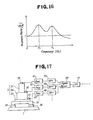
- Fig. 16 is a graph showing a typical frequency characteristic of the response ratio in the apparatus of Fig. 15, which is featured by a plurality of peaks in the response ratio at corresponding frequencies f1, f2.
- Such an object 3 can be regarded as a multiple freedom degree system comprising a lower half 3A and an upper half 3B.
- the object 3 is suspended by the suspension 2 via a table 26 fixedly secured to the bottom surface thereof.
- each low pass filter 15, 10, 6 in Fig. 1 it is desirable for each low pass filter 15, 10, 6 in Fig. 1 to have a frequency range which includes the peak frequencies f1, f2 in Fig. 16.
- the inverse vibration generating circuit 20 may be arranged as shown in Figs. 5-9.
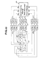
- Fig. 17 is a block diagram of an arrangement wherein the vibration control apparatus according to the invention is used to control the vibration of object 3 with a plurality of regions or multiple degrees of freedom
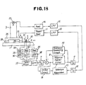
- Fig. 18 is a block diagram of an arrangement wherein the apparatus according to the invention is used to control vibration with a multiple degrees of freedom or a plurality of vibration directions.
- Figs. 19, 20 and 21 are graphs respectively showing the frequency characteristic of the response ratio, the frequency characteristic of the vibration acceleration level, and the waveform of the acceleration amplitude in the apparatus shown in Figs. 17 and 18.
- the object 3 as a whole can be regarded as including three regions 3A, 3B and 3C.
- the regions 3A, 3B and 3C are provided at respectively predetermined locations with vibration sensors 39, 40 and 49.
- These sensors 39, 40, 49 are connected to amplifiers 41, 42 and 47 for amplifying the signals generated by the sensors.
- the signals amplified by the amplifiers 41, 42 and 47 are passed through band-pass filters (BPF) 43, 44 and 48, if necessary, and then added with each other by means of the signal mixer 45.
- BPF band-pass filters
- the vibration sensors 39, 40, 49, amplifiers 41, 42, 47, band-pass filters 43, 44, 48, etc. are preferably provided by such minimized number as to enable the overall vibration reduction of the object 3.
- band-pass filters (BPF) 43, 44, 48 shown in Fig. 17 may be replaced with highpass filters or low-pass filters.
- the amplifiers 41, 42, 47 may be directly connected to the mixer 45.
- Fig. 18 corresponds to the situation b) above, wherein the object 3 is formed of a hollow columnar steel body of the size of 0.5 x 0.5 x 1.2 m and of the weight of 480 kg.
- the object 3 is arranged on and fixedly secured to a table which, in turn, is supported by four vibration-insulating rubber members 28. By measuring the vibration of the object 3, it has been found that there are resonance peaks at two points near 4 Hz and 9 Hz.
- the direction in which the vibration is to be controlled is horizontal axial direction X, as shown in Fig. 18.
- the vibration control apparatus of Fig. 18 it is necessary for the vibration control apparatus of Fig. 18 to simultaneously reduce the two resonance peaks near 4 Hz and 9 Hz.
- two kinds of vibration signals of the base member 1 are detected, one being the vibration in the direction X for controlling the 4 Hz peak and the other being the vibration in the direction Z for controlling the 9 Hz peak, and these signals are passed through the band-pass filters 37, 38, respectively, and added with each other by the mixer 29.
- vibration components in the model of Fig. 18 were in the directions X and Z, if the vibration component in the direction Y also is required, the component in that direction is to be detected by the sensor 32 whose output signal is passed through the amplifier 33 and filter 36 and is then supplied to the mixer 29 in a similar manner.
- Figs. 19 and 20 are graphs respectively showing the response ratio I of the object 3 with reference to the movable base member 1 and the vibration acceleration level of the object 3, both under condition (A) in which the vibration control apparatus with the arrangement shown in Fig. 18 is switched into OFF state, and condition (B) in which the vibration control apparatus is switched into ON state and the filter coefficients of the adaptive digital filter 8 have been converged.
- the vibration of the movable base member 1 has been represented by the output signal from the mixer 29, which has been obtained by mixing the signals corresponding the vibration components in the directions X and Z.
- the present invention makes it possible to significantly reduce the two resonance peaks (near 4 Hz and 9 Hz) in the frequency range of 12 Hz or less of the object 3, to realize a resonance-free state with the response ratio of 1 or less, as particularly shown in Fig. 19. It is also clear that the present invention makes it possible to significantly reduce the vibration acceleration of the object 3.
- Fig. 21 is a graph showing the vibration acceleration amplitude of the object 3 under the condition (A) in which the vibration control apparatus with the arrangement is switched into OFF state, and condition (B) in which the vibration control apparatus is switched into ON state and the filter coefficients of the adaptive digital filter 8 have been converged.
- the experimental results shown in Fig. 22 also reveals clearly that it is possible according to the invention to significantly reduce the vibration amplitude of the object 3 to as low as noise level.
- the vibration of the object 3 exhibits a plurality of resonance peaks having correlation to the vibration components of the base member 1 in different directions (X, Y, Z)
- the wide range vibration of the object 3 including the peaks can be significantly and simultaneously reduced by adding signals corresponding to the correlated vibration components of the base member 1 by means of the mixer 29, and using the mixed signal as an input signal to the adaptive digital filter 8.
- the object 3 is complicated in configuration and includes, for example, a plurality of regions as shown in Fig. 17, it is also possible to significantly reduce the overall vibration of the object 3, using a signal obtained by mixing the signals corresponding to the vibrations of the regions by means of the mixer 45 (Fig. 17).
- the vibration control apparatus has been generally explained as including elements shown in the block diagrams, serving to reduce the vibration which is transmitted from the base member 1 to the object 3 via suspension 2.
- elements shown in the block diagrams serving to reduce the vibration which is transmitted from the base member 1 to the object 3 via suspension 2.
- some practical examples dealing with various application fields of the invention will be explained.
- Fig. 22 shows a model applied to the vibration control of a seat in a vehicle, such as automobile, aircraft. vessel, etc.
- a passenger 51 is seated on a seat 52 to which is transmitted a vibration from a vehicle frame 54 via suspension 55.
- a vibration sensor 56 is secured to the seat 52 which is applied with an inverse vibration by an actuator 53 based on the vibration of the seat as detected by the sensor 56.
- Fig. 23 shows a model applied to the vibration control of a sprung mass 61 above a suspension 58.
- vibration is transmitted from a road surface 60 via tire 59 and suspension 58 to the sprung mass 61, and is reduced by an applying an inverse vibration by means of an actuator 62.
- the actuator is operated based on the vibration of the sprung mass 61 as detected by a vibration sensor 63 secured to the mass 61, and the vibration of the unsprung mass 64 detected by a vibration sensor 71 secured to the mass 64.
- Fig. 24 show a model applied to the control of vibration generated by an engine 65 in a vehicle, such as automobile, aircraft, vessel, etc.
- the engine 65 as a vibration source corresponds to the movable base member 1, and is mounted on a vehicle frame 66 via vibration-isolating suspension 67.
- the frame 66 forms an object 3 whose vibration is to be reduced.
- the vibration which is transmitted from the engine 65 via suspension 67 to the frame 66 can be effectively reduced by application of inverse vibration to the frame 66 by means of an actuator 68.
- the frame 66 and the engine 65 are respectively provided with vibration sensors 69 and 70.
- Fig. 34 is a block diagram showing a basic arrangement similar to that of Fig. 10.
- the apparatus is for reducing the vibration of an object 103 mounted on a table 104 which is supported on a base member 101 by suspension 102.
- the apparatus includes vibration sensors 105, 106 secured to the table 104 and the object 103, respectively.
- the sensor 105 is connected to amplifier 108 which, in turn, is connected to a low-pass filter 111.
- the sensor 106 is connected to amplifier 109 which, in turn, is connected to a low-pass filter 113.
- the output signals of these low-pass filters 111, 113 are supplied to an adaptive-type inverse vibration generating circuit (IVGC) 114 whose output signal is supplied to actuator 107 via low-pass filter 112 and power amplifier 110.
- IVGC adaptive-type inverse vibration generating circuit
- the inverse vibration generating circuit 114 may include adaptive-type digital filter 118, signal processor 121 for executing adaptive algorithm, A/D converters 117, 122, D/A converter 119, resonance preventing circuit 116 and delay circuit 120.
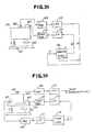
- the vibration control apparatus When the object 103 is formed of a substantially rigid body and directly mounted on the table 104 without vibration-isolating means therebetween such that they vibrate jointly, or when the object 103 is directly supported by the suspension 102 without the table 104, the vibration control apparatus according to the embodiment of Fig. 34 may be modified as shown in Fig. 38.
- the apparatus includes a closed loop wherein the inverse vibration applied by the actuator 107 to the table 104 is detected by the sensor 105, passed through the digital filter 118 and supplied again to the actuator 107, there is an undesirable tendency of resonance to deteriorate the stability of the apparatus.
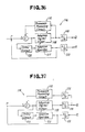
- Figs. 39 and 40 are block diagrams corresponding to those of Figs. 34 and 38, respectively, wherein the filter coefficients of the adaptive-type digital filter 118 in the inverse vibration generating circuit 114 are fixed in order to form fixed-type inverse vibration generating circuit 115.
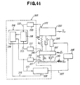
- Fig. 41 is a block diagram showing another embodiment of the vibration control apparatus according to the invention which is similar to that of Fig. 34, but in which the actuator 107 is arranged at a different location, i.e. between the base member 101 and the table 104, as in the embodiment of Fig. 11.
- Fig. 42 is a block diagram similar to Fig. 25, showing another example of basic arrangement of the circuit for reducing two-dimensional vibration in the vibration control apparatus according to the invention.
- Fig. 43 is a block diagram similar to Fig. 39, showing another example of basic arrangement of the circuit for reducing three-dimensional vibration in the vibration control apparatus according to the invention.
- the present invention can also be effectively applied to actively control vibrations of a plurality of objects simultaneously, which are mounted on a movable base member and connected either in series or parallel with each other. Embodiments for such particular applications will be explained below.
- Fig. 44 is a block diagram showing one embodiment of the apparatus according to the invention, which is for controlling the vibration of two objects 201 and 202 stacked one above the other. More particularly, the object 201 is supported on a movable base member 210 (vibration source) via a vibration- isolating suspension 3 including a spring k 1 and a damper C1 , while the object 202 is supported on the object 201 via another vibration-isolating suspension 4 including a spring k 2 and a damper C 2 .
- An actuator 206 is arranged between the objects 201, 202 for actively applying vibration to these objects.
- the actuator 206 is driven by a driver 208 which is supplied with a signal 207 from a digital filter 209 of an adaptive-type vibration control system 205.
- the digital filter 209 is supplied with a signal 213 from an amplifier 212, which is for amplifying the output signal of a vibration sensor 211 secured to the base member 210.
- the digital filter 209 which may be of FIR-type, SIR- type or combination thereof, is so arranged that the filter coefficients of the digital filter 209 can be properly varied on a real-time basis in a successive manner, based on control signal 215 from an adaptive control circuit 214.
- the control signal 215 is for controlling the digital filter 209 to select the optimum filter coefficients and to thereby minimize the sum of the vibration errors of the objects 201, 202 from zero level.
- the objects 201, 202, whose vibrations are to be reduced, are provided with vibration sensors (monitor sensors) 216, 217.
- the output signals from the sensors 216, 217 are respectively amplified by amplifiers 220, 221 and are then supplied to the adaptive control circuit 214. More particularly, first of all, errors from zero level of the output signals 222, 223 of the amplifiers 220, 221 are calculated and added by an error operating circuit 218. The added error is then supplied to an adaptive control signal generating circuit 219 which generates and supplies to the digital filter 209 the abovementioned control signal 215 for rewriting the filter coefficients of the digital filter 209 so as to minimize the error.
- the error operating circuit 218 may, for example, be a circuit having a function to calculate square error from zero level of each input signal 222, 223, and then calculate the sum of the square errors. Instead of the zero level, the square errors bay be calculated with reference to a predetermined waveform. Moreover, instead of mean square error, other error standards may be used. In particular, not only errors in time domain of the signal, but also errors in frequency domain may be used by means of FFT (Fast Fourier Transformation) method or the like.
- FFT Fast Fourier Transformation
- LMS least mean square
- the adaptive control circuit 214 in the vibration control system 205 serves to determine the filter coefficients of the digital filter 209 to minimize the signals representing the vibrations of the objects 201, 202 which are stacked with each other.
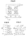
- Figs. 45, 46 and 47 illustrate variations of the arrangement of Fig. 44, which also serve to simultaneously reduce the vibrations of a plurality of objects mi, m 2 ... .
- the objects are shown as being arranged in multiple stages, with some of the objects being optionally arranged in parallel connection (Fig. 45).
- actuators 206 are secured to the objects themselves as inertia mass actuators.
- monitor sensors si are secured to a plurality of selected objects m; whose vibrations are to be reduced, and actuators a; (206) are either arranged between these objects m ; , or connected to appropriate locations thereof.
- the output signals from the monitor sensors s are supplied to the error operating circuit 218 in the control circuit (Fig. 44) of the adaptive-type vibration control system 205, while the output signal from the vibration source sensor 211 on the base member 210 is supplied to the digital filter 209 of the system 205, thereby to simultaneously reduce the vibrations of a plurality of predetermined objects mi.
- the apparatus for reducing vibrations of a plurality of objects may include, if necessary, a plurality of sets for each of actuator drivers 208 corresponding to respective actuators a i , digital filters 209 and adaptive control circuits 214.
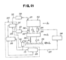
- Fig. 48 is a block diagram showing another embodiment of the invention wherein the error operation circuit 218 in Fig. 44 is replaced by a signal mixer 231. That is, the output signals of the amplifiers 220, 221 connected to the monitor sensors 216, 217 are supplied to the signal mixer 231 where they are mixed with each other. The output signal of the signal mixer 231, in turn, is supplied to the adaptive control signal generating circuit 219 in order to calculate the control signal 215 for rewriting the filter coefficients of the digital filter 209.
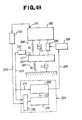
- Fig. 49 is a block diagram showing still another embodiment of the present invention, wherein the vibration source sensor 211 is secured to the object 201 to function as a monitor sensor also.
- the output signal of the sensor 211 is supplied to both the digital filter 20 and the error operating circuit 218.
- the output signal from a monitor sensor 217 secured to another object 202 is supplied to the error operating circuit 218.
- the adaptive control signal generating circuit 219 determines the filter coefficients of the digital filter 209 such that the error calculated by the error operating circuit 209 can be minimized, and the so determined filter coefficients are then transmitted to the digital filter 209 as a control signal 215.
- the vibration source sensor 211 secured to the object 201 generates a signal which is passed through the digital filter 209 and supplied to the actuator driver 206 to drive the actuator 208 and thereby control the vibrations of the objects 201 and 202.
- the arrangement shown in Fig. 49 includes feed-back elements for performing a feed-back control of the vibration of the lower object 201 with the adaptive-type filter, as well as feed-forward elements for performing a feed-forward control of the vibration of the upper object 202, the two types of the control being simultaneously carried out to achieve effective reduction of the vibrations of the lower and upper objects 201, 202.
- the apparatus for reducing vibrations of a plurality of objects may include a plurality of sets for each of actuators a;, actuator drivers 208, digital filters 209 and adaptive control circuits 214.
- the digital filter 209 may be of FIR-type, IIR-type or combination thereof. The filter coefficients of the digital filter 209 may be properly controlled in accordance with the vibration environment, e.g. by switching from adaptive mode to fixed mode, and vice versa.
- the vibration applied to the movable base member 210 may be a random vibration, periodic vibration, pulsive vibration, etc.
- the vibration control apparatus according to the invention is effective to any type of vibration.
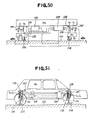
- Fig. 50 is a block diagram showing an application of the invention to an automobile suspension system.
- the road surface 233 corresponds to the movable base member 210 in Fig. 44, and the vibration of the road surface relative to the automobile is detected on real-time basis by non-contact type roadsurface sensors 234, 235 and unsprung mass monitor sensors 236, 237 both on front and rear sides, whose output signals are supplied to the adaptive-type vibration control system 5.
- Monitor sensors 236, 237, 238, 239 are secured to unsprung mass m i , m 2 (axle, wheel, etc.) and sprung mass m 3 (vehicle body, engine, etc.), and the output signals of these sensors are supplied to the control system 5 in order to determine on real-time basis the filter coefficients of the digital filter 209 such that the output signals (or errors from predetermined value) can be minimized.
- hydraulic actuators 241, 242 on front and rear sides are driven by respective actuator drivers 208 to apply inverse vibrations to the unsprung mass m i , m 2 and sprung mass m3.
- the application of inverse vibrations serve to significantly reduce vibrations of both the sprung mass and unsprung mass of the vehicle transmitted from the road surface 233 to improve driver's and passengers' comfort and maneuvability of the vehicle.
- the filter coefficients of the digital filter 209 are caused to change accordingly so as to effect an adaptive control and optimize or minimize the vibration.
- the road surface sensors 234, 235 are generally secured to axles, and may each be formed of an ultrasonic sensor, laser sensor, etc.
- the hydraulic actuators 241, 242 on front and rear sides are connected either in series or parallel with relevant spring ki, k 2 and shock absorber c 1 , C2 of the suspensions, and arranged between the unsprung mass mi, m 2 and sprung mass m 3 .
- they may be secured to the unsprung mass m 1 , m 2 or sprung mass m 3 as inertia-mass type actuator, provided that a necessary inverse vibration can be applied by such an arrangement.
- the actuators 241, 242 may be replaced by pneumatic actuators adapted to vary the pneumatic spring inner pressure.
- Fig. 51 is a schematic view showing an actual example of the arrangement of Fig. 50.
- the hydraulic system including hydraulic actuators 241, 242 may be operated by hydraulic pressure used generally for power steering device or the like.
- the circuit for the adaptive-type vibration control system 205 may have a compact arrangement of a single- or twin-board, and driven by batteries mounted on the vehicle as an electric power source.
- Fig. 51 makes use of the arrangement of Fig. 44, though the arrangement of Fig. 49 may be applied to such a system when the road surface sensors 234, 235 are omitted.
- the objects 201, 202 in Fig. 49 correspond to the unsprung mass m1, m 2 and sprung mass m 3 , respectively.
- Fig. 52 is a schematic view showing a model wherein a seat m 3 of a vehicle, such as an automobile or aircraft, is supported on the vehicle body (sprung mass m 2 ) via spring k 3 and damper c3, and is applied with inverse vibration by an actuator a to reduce the vibration.
- a seat m 3 of a vehicle such as an automobile or aircraft
- Fig. 53 is a schematic view showing a model wherein a cabin m 3 of a truck is supported on the vehicle body (sprung mass m 2 ) via a cabin suspension including spring k 3 and damper C3 , and is applied with inverse vibration by an actuator a to reduce the vibration.
- Fig. 54 is a schematic view showing a model for simultaneously reducing the vibration transmitted from the road surface 210 to the vehicle body m 2 via tire/wheel assembly m i , k i , c 1 , and also the vibration transmitted from an engine m 3 , which is supported on the vehicle body m 2 , to the vehicle body m 2 via engine mount k 3 , C3 .
- the actuator a for applying the inverse vibration is arranged between the vehicle body m 2 and the engine m 3 , in parallel with the assembly k ; , ci, though it may be secured to the object mi itself as an inertia-mass type actuator.
- Application of the invention to such an arrangement also makes it possible to significantly reduce the vibrations transmitted from the road surface 210 and engine to the vehicle body m 2 .
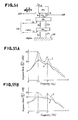
- Figs. 55A and 55B are graphs showing the frequency characteristics of the vibration acceleration response ratio versus the vibration acceleration of the movable base member 210, under situation (X) in which the adaptive-type vibration control according to the invention is effected, and situation (Y) without the adaptive-type vibration control.
- Fig. 55A corresponds to the response ratio of the lower object 201
- Fig. 55B corresponds to the response ratio of the lower object 20. It is clear that, for both of the objects 201, 202, it is readily possible to significantly reduce the vibration by 10-20dB at two resonance peak frequencies of near 2.2 Hz and 5 Hz.
- Figs. 56A and 56B are graphs showing the waveforms of the vibration acceleration amplitude of the objects 201, 202, under situation (X) in which the adaptive-type vibration control according to the invention is effected, and situation (Y) without the adaptive-type vibration control.
- Fig. 56A corresponds to the vibration acceleration amplitude of the objects 201
- Fig. 56B corresponds to the vibration acceleration amplitude of the objects 202. It is clear that, by effecting the adaptive-type vibration control according to the invention, the vibration acceleration amplitude of the objects 201, 202 can be reduced to less than one third as compared with that under the situation (Y) in which the adaptive-type vibration control is not effected.
- the present invention provides an adaptive-type active vibration control apparatus for significantly reducing the vibration of various objects without being affected by resonance peak frequencies, which is particularly suitable when the object is applied with vibration over a wide frequency range, or with vibration of a random or periodic nature.
Landscapes
- Engineering & Computer Science (AREA)
- Physics & Mathematics (AREA)
- General Engineering & Computer Science (AREA)
- Mechanical Engineering (AREA)
- Acoustics & Sound (AREA)
- Aviation & Aerospace Engineering (AREA)
- General Physics & Mathematics (AREA)
- Automation & Control Theory (AREA)
- Vibration Prevention Devices (AREA)
Applications Claiming Priority (10)
| Application Number | Priority Date | Filing Date | Title |
|---|---|---|---|
| JP01208375A JP3122101B2 (ja) | 1989-08-11 | 1989-08-11 | 振動制御装置 |
| JP208375/89 | 1989-08-11 | ||
| JP21787889 | 1989-08-24 | ||
| JP217878/89 | 1989-08-24 | ||
| JP21787789 | 1989-08-24 | ||
| JP217877/89 | 1989-08-24 | ||
| JP61591/90 | 1990-03-13 | ||
| JP2061591A JPH03219139A (ja) | 1989-08-24 | 1990-03-13 | 振動制御装置 |
| JP2061592A JPH03219140A (ja) | 1989-08-24 | 1990-03-13 | 振動制御装置 |
| JP61592/90 | 1990-03-13 |
Publications (3)
| Publication Number | Publication Date |
|---|---|
| EP0412853A2 true EP0412853A2 (de) | 1991-02-13 |
| EP0412853A3 EP0412853A3 (de) | 1992-12-30 |
| EP0412853B1 EP0412853B1 (de) | 1997-03-26 |
Family
ID=27523673
Family Applications (1)
| Application Number | Title | Priority Date | Filing Date |
|---|---|---|---|
| EP19900308893 Expired - Lifetime EP0412853B1 (de) | 1989-08-11 | 1990-08-13 | Aktives Schwingungssteuergerät |
Country Status (2)
| Country | Link |
|---|---|
| EP (1) | EP0412853B1 (de) |
| DE (1) | DE69030289T2 (de) |
Cited By (26)
| Publication number | Priority date | Publication date | Assignee | Title |
|---|---|---|---|---|
| EP0516537A1 (de) * | 1991-05-31 | 1992-12-02 | Hutchinson | Vorrichtung zur Dämpfung der periodischen Schwingungen einer mechanischen Struktur |
| EP0498926A3 (en) * | 1991-02-12 | 1993-05-26 | Firma Carl Freudenberg | Hydraulically-damped elastic mount for machine support |
| EP0560364A1 (de) * | 1992-03-12 | 1993-09-15 | Honda Giken Kogyo Kabushiki Kaisha | Schwingungs- und Geräuschregelungssystem für Kraftfahrzeuge |
| FR2692017A1 (fr) * | 1992-06-03 | 1993-12-10 | Clausin Jacques | Dispositif de réduction de la transmission des vibrations de machines vibrantes à l'environnement par l'intermédiaire de leurs liaisons. |
| EP0579182A1 (de) * | 1992-07-14 | 1994-01-19 | Iveco Magirus Ag | Aktive Fahrzeugfederung, insbesondere Fahrerhausfederung eines Nutzfahrzeuges |
| US5332061A (en) * | 1993-03-12 | 1994-07-26 | General Motors Corporation | Active vibration control system for attenuating engine generated vibrations in a vehicle |
| GB2277360A (en) * | 1993-04-23 | 1994-10-26 | Moog Inc | Actively adjusting and controlling a resonant mass-spring system |
| DE4441726A1 (de) * | 1993-11-23 | 1995-07-06 | Moog Inc | Verfahren zum Regeln des Anlegens von Gegenvibrationen an eine Anordnung |
| DE19547314A1 (de) * | 1994-12-27 | 1996-07-11 | Honda Motor Co Ltd | Aktives Motorlagersystem zur Steuerung von Vertikalbewegung einer Fahrzeugkarosserie |
| WO1998016760A3 (en) * | 1996-10-15 | 1998-05-22 | Ronnie Chi Nang Leung | Vibration attenuation system |
| WO1999050720A1 (en) * | 1998-04-01 | 1999-10-07 | Lord Corporation | Dynamic system controller |
| DE10116440A1 (de) * | 2001-04-02 | 2002-10-17 | Daimler Chrysler Ag | Einrichtung und Verfahren zur Reduktion von Schwingungen eines Fahrzeuges und Fahrwerk für Schienenfahrzeuge |
| WO2003089284A1 (de) * | 2002-04-22 | 2003-10-30 | Bombardier Transportaton Gmbh | Verfahren zur verminderung der schallübertragung in fahrzeugen, fahrwerk für fahrzeuge und aktuator |
| EP1482490A2 (de) | 2003-05-28 | 2004-12-01 | Olympus Corporation | Gerät zur Ansteuerung eines Aktuators |
| EP1304499A4 (de) * | 2000-07-13 | 2005-02-02 | Ebara Corp | Schwingungsisolierende vorrichtung mit magnetischer schwebevorrichtung |
| EP1445132A3 (de) * | 2003-02-05 | 2005-02-02 | Nissan Motor Company, Limited | Elektromagnetisches Aufhängungssystem |
| FR2905634A1 (fr) * | 2006-09-07 | 2008-03-14 | Peugeot Citroen Automobiles Sa | Voile mince, notamment surface vitree telle qu'un pare-brise de vehicule automobile, comportant au moins un moyen d'amortissement actif des vibrations |
| US7818109B2 (en) | 2007-10-23 | 2010-10-19 | Bose Corporation | Methods and apparatus for securing an active vehicle seat |
| US7865338B2 (en) * | 2005-04-07 | 2011-01-04 | Belimo Holding Ag | Suppression of vibrations |
| US7962261B2 (en) | 2007-11-12 | 2011-06-14 | Bose Corporation | Vehicle suspension |
| US7983813B2 (en) | 2004-10-29 | 2011-07-19 | Bose Corporation | Active suspending |
| EP2351657A3 (de) * | 2010-01-12 | 2012-02-22 | MAN Truck & Bus AG | Nutzfahrzeug mit einer gelenkten Achse als Schwingungstilger |
| US8401735B2 (en) | 2006-05-08 | 2013-03-19 | Shinko Electric Co., Ltd. | Damping apparatus for reducing vibration of automobile body |
| US9846425B2 (en) | 2015-03-31 | 2017-12-19 | Bose Corporation | Retrieving pre-determined controller parameters to isolate vibrations in an authorized payload |
| US11630425B2 (en) | 2017-09-08 | 2023-04-18 | Mitsubishi Electric Corporation | Servo control device |
| CN120742993A (zh) * | 2025-08-13 | 2025-10-03 | 江苏鸾翔机电工程有限公司 | 一种微振平台减震控制方法及系统 |
Family Cites Families (7)
| Publication number | Priority date | Publication date | Assignee | Title |
|---|---|---|---|---|
| JPS5617754A (en) * | 1979-07-20 | 1981-02-19 | Hitachi Ltd | Vehicle vibration controller |
| EP0067548A1 (de) * | 1981-06-02 | 1982-12-22 | M.L. Aviation Company Limited | Schwingungsdämpfer |
| JPS59133595A (ja) * | 1982-11-26 | 1984-07-31 | ロ−ド・コ−ポレ−シヨン | 能動音響減衰装置 |
| GB2165667B (en) * | 1984-07-20 | 1988-04-20 | Univ Southampton | Method of reducing the transmission of vibrations |
| DE3786165T2 (de) * | 1986-10-07 | 1993-10-14 | Adaptive Control Ltd | Aktive vibrationskontrolle. |
| JP2814241B2 (ja) * | 1987-09-25 | 1998-10-22 | 株式会社ブリヂストン | 振動制御装置 |
| JPH01284793A (ja) * | 1988-05-11 | 1989-11-16 | Canon Inc | 基板支持装置 |
-
1990
- 1990-08-13 EP EP19900308893 patent/EP0412853B1/de not_active Expired - Lifetime
- 1990-08-13 DE DE1990630289 patent/DE69030289T2/de not_active Expired - Fee Related
Cited By (42)
| Publication number | Priority date | Publication date | Assignee | Title |
|---|---|---|---|---|
| EP0498926A3 (en) * | 1991-02-12 | 1993-05-26 | Firma Carl Freudenberg | Hydraulically-damped elastic mount for machine support |
| US5369348A (en) * | 1991-05-31 | 1994-11-29 | Hutchinson S.A. | Device for attenuating the periodic vibrations of a mechanical structure |
| FR2677096A1 (fr) * | 1991-05-31 | 1992-12-04 | Hutchinson Sa | Dispositif d'attenuation des vibrations periodiques d'une structure mecanique. |
| EP0516537A1 (de) * | 1991-05-31 | 1992-12-02 | Hutchinson | Vorrichtung zur Dämpfung der periodischen Schwingungen einer mechanischen Struktur |
| US5386372A (en) * | 1992-03-12 | 1995-01-31 | Honda Giken Kogyo Kabushiki Kaisha | Vibration/noise control system for vehicles |
| EP0778559A3 (de) * | 1992-03-12 | 1999-01-20 | Honda Giken Kogyo Kabushiki Kaisha | Schwingungs- und Geräuschregelungssystem für Kraftfahrzeuge |
| EP0560364A1 (de) * | 1992-03-12 | 1993-09-15 | Honda Giken Kogyo Kabushiki Kaisha | Schwingungs- und Geräuschregelungssystem für Kraftfahrzeuge |
| FR2692017A1 (fr) * | 1992-06-03 | 1993-12-10 | Clausin Jacques | Dispositif de réduction de la transmission des vibrations de machines vibrantes à l'environnement par l'intermédiaire de leurs liaisons. |
| EP0579182A1 (de) * | 1992-07-14 | 1994-01-19 | Iveco Magirus Ag | Aktive Fahrzeugfederung, insbesondere Fahrerhausfederung eines Nutzfahrzeuges |
| US5332061A (en) * | 1993-03-12 | 1994-07-26 | General Motors Corporation | Active vibration control system for attenuating engine generated vibrations in a vehicle |
| GB2277360A (en) * | 1993-04-23 | 1994-10-26 | Moog Inc | Actively adjusting and controlling a resonant mass-spring system |
| DE4413447B4 (de) * | 1993-04-23 | 2004-02-12 | Moog Inc. | Verfahren und Vorrichtung zum aktiven Einstellen und Steuern eines resonanten Masse-Feder-Systems |
| GB2277360B (en) * | 1993-04-23 | 1997-03-19 | Moog Inc | Method and apparatus for actively adjusting and controlling a resonant mass-spring system |
| DE4441726B4 (de) * | 1993-11-23 | 2004-07-15 | Moog Inc. | Regelvorrichtung und Verfahren zum Dämpfen von sinusförmigen Vibrationen einer Anordnung sowie zum Dämpfen von sinusförmigem Rauschen an einer Umhüllung |
| DE4441726A1 (de) * | 1993-11-23 | 1995-07-06 | Moog Inc | Verfahren zum Regeln des Anlegens von Gegenvibrationen an eine Anordnung |
| DE19547314C2 (de) * | 1994-12-27 | 1999-01-28 | Honda Motor Co Ltd | Aktives Motorlagersystem zur Steuerung von Vertikalbewegung einer Fahrzeugkarosserie |
| DE19547314A1 (de) * | 1994-12-27 | 1996-07-11 | Honda Motor Co Ltd | Aktives Motorlagersystem zur Steuerung von Vertikalbewegung einer Fahrzeugkarosserie |
| WO1998016760A3 (en) * | 1996-10-15 | 1998-05-22 | Ronnie Chi Nang Leung | Vibration attenuation system |
| WO1999050720A1 (en) * | 1998-04-01 | 1999-10-07 | Lord Corporation | Dynamic system controller |
| EP1304499A4 (de) * | 2000-07-13 | 2005-02-02 | Ebara Corp | Schwingungsisolierende vorrichtung mit magnetischer schwebevorrichtung |
| DE10116440A1 (de) * | 2001-04-02 | 2002-10-17 | Daimler Chrysler Ag | Einrichtung und Verfahren zur Reduktion von Schwingungen eines Fahrzeuges und Fahrwerk für Schienenfahrzeuge |
| DE10116440B4 (de) * | 2001-04-02 | 2007-06-06 | Eads Deutschland Gmbh | Einrichtung und Verfahren zur Reduktion von Schwingungen eines Fahrzeuges und Fahrwerk für Schienenfahrzeuge |
| WO2003089284A1 (de) * | 2002-04-22 | 2003-10-30 | Bombardier Transportaton Gmbh | Verfahren zur verminderung der schallübertragung in fahrzeugen, fahrwerk für fahrzeuge und aktuator |
| EP1445132A3 (de) * | 2003-02-05 | 2005-02-02 | Nissan Motor Company, Limited | Elektromagnetisches Aufhängungssystem |
| US7270335B2 (en) | 2003-02-05 | 2007-09-18 | Nissan Motor Co., Ltd. | Electromagnetic suspension apparatus for automotive vehicles and method for controlling electric motor of the same |
| CN100379590C (zh) * | 2003-02-05 | 2008-04-09 | 日产自动车株式会社 | 用于车辆的电磁悬架设备以及控制其电动机的方法 |
| EP1482490A2 (de) | 2003-05-28 | 2004-12-01 | Olympus Corporation | Gerät zur Ansteuerung eines Aktuators |
| US8548678B2 (en) | 2004-10-29 | 2013-10-01 | Bose Corporation | Active suspending |
| US7983813B2 (en) | 2004-10-29 | 2011-07-19 | Bose Corporation | Active suspending |
| US7865338B2 (en) * | 2005-04-07 | 2011-01-04 | Belimo Holding Ag | Suppression of vibrations |
| US8504239B2 (en) | 2006-05-08 | 2013-08-06 | Shinko Electric Co., Ltd. | Damping apparatus for reducing vibration of automobile body |
| US8401735B2 (en) | 2006-05-08 | 2013-03-19 | Shinko Electric Co., Ltd. | Damping apparatus for reducing vibration of automobile body |
| US8626386B2 (en) | 2006-05-08 | 2014-01-07 | Shinko Electric Co., Ltd. | Damping apparatus for reducing vibration of automobile body |
| US8818625B2 (en) | 2006-05-08 | 2014-08-26 | Shinko Electric Co., Ltd. | Damping apparatus for reducing vibrations |
| US8892338B2 (en) | 2006-05-08 | 2014-11-18 | Shinko Electric Co., Ltd. | Damping apparatus for reducing vibration of automobile body |
| FR2905634A1 (fr) * | 2006-09-07 | 2008-03-14 | Peugeot Citroen Automobiles Sa | Voile mince, notamment surface vitree telle qu'un pare-brise de vehicule automobile, comportant au moins un moyen d'amortissement actif des vibrations |
| US7818109B2 (en) | 2007-10-23 | 2010-10-19 | Bose Corporation | Methods and apparatus for securing an active vehicle seat |
| US7962261B2 (en) | 2007-11-12 | 2011-06-14 | Bose Corporation | Vehicle suspension |
| EP2351657A3 (de) * | 2010-01-12 | 2012-02-22 | MAN Truck & Bus AG | Nutzfahrzeug mit einer gelenkten Achse als Schwingungstilger |
| US9846425B2 (en) | 2015-03-31 | 2017-12-19 | Bose Corporation | Retrieving pre-determined controller parameters to isolate vibrations in an authorized payload |
| US11630425B2 (en) | 2017-09-08 | 2023-04-18 | Mitsubishi Electric Corporation | Servo control device |
| CN120742993A (zh) * | 2025-08-13 | 2025-10-03 | 江苏鸾翔机电工程有限公司 | 一种微振平台减震控制方法及系统 |
Also Published As
| Publication number | Publication date |
|---|---|
| DE69030289D1 (de) | 1997-04-30 |
| EP0412853B1 (de) | 1997-03-26 |
| EP0412853A3 (de) | 1992-12-30 |
| DE69030289T2 (de) | 1997-09-04 |
Similar Documents
| Publication | Publication Date | Title |
|---|---|---|
| EP0412853B1 (de) | Aktives Schwingungssteuergerät | |
| US5409078A (en) | Adaptively controlled vibration damping support apparatus for vehicle power unit including engine | |
| US6193206B1 (en) | Active vibration isolator | |
| EP0739766B1 (de) | Verfahren zum Begrenzen einer Bewegung unter Verwendung eines einstellbaren Dämpfers | |
| US5327061A (en) | Force (torque) nulling inertially servoed structural interface | |
| US5712783A (en) | Control method for semi-active damper | |
| AU661258B2 (en) | Active acoustic control system matching model reference | |
| EP0397488B1 (de) | Radeinheit-Aufhängung | |
| US5276623A (en) | System for controlling suspension deflection | |
| US4929874A (en) | Vibration control system | |
| US5374077A (en) | Pneumatically damped vehicle suspension system | |
| Kim et al. | Decentralized control for multichannel active vibration isolation | |
| US5792948A (en) | Active vibration control apparatus for vehicle | |
| US5219037A (en) | Component mount assembly providing active control of vehicle vibration | |
| US6186485B1 (en) | Vibration insulating apparatus and method | |
| Misol et al. | Experimental investigation of different active noise control concepts applied to a passenger car equipped with an active windshield | |
| US8086377B2 (en) | Suspension control apparatus | |
| JPH04500191A (ja) | 運動の進行を減衰させる方法及び装置 | |
| JP3122101B2 (ja) | 振動制御装置 | |
| US6115658A (en) | No-jerk semi-active skyhook control method and apparatus | |
| US9648418B2 (en) | Active noise cancellation apparatus | |
| JPH03219139A (ja) | 振動制御装置 | |
| Simon | An investigation of the effectiveness of skyhook suspensions for controlling roll dynamics of sport utility vehicles using magneto-rheological dampers | |
| US6364064B1 (en) | Piezoceramic elevator vibration attenuator | |
| Sapiński | Real-time control for a magnetorheological shock absorber in a driver seat |
Legal Events
| Date | Code | Title | Description |
|---|---|---|---|
| PUAI | Public reference made under article 153(3) epc to a published international application that has entered the european phase |
Free format text: ORIGINAL CODE: 0009012 |
|
| AK | Designated contracting states |
Kind code of ref document: A2 Designated state(s): DE FR GB |
|
| PUAL | Search report despatched |
Free format text: ORIGINAL CODE: 0009013 |
|
| AK | Designated contracting states |
Kind code of ref document: A3 Designated state(s): DE FR GB |
|
| 17P | Request for examination filed |
Effective date: 19930108 |
|
| 17Q | First examination report despatched |
Effective date: 19940708 |
|
| GRAG | Despatch of communication of intention to grant |
Free format text: ORIGINAL CODE: EPIDOS AGRA |
|
| GRAH | Despatch of communication of intention to grant a patent |
Free format text: ORIGINAL CODE: EPIDOS IGRA |
|
| GRAH | Despatch of communication of intention to grant a patent |
Free format text: ORIGINAL CODE: EPIDOS IGRA |
|
| GRAA | (expected) grant |
Free format text: ORIGINAL CODE: 0009210 |
|
| AK | Designated contracting states |
Kind code of ref document: B1 Designated state(s): DE FR GB |
|
| REF | Corresponds to: |
Ref document number: 69030289 Country of ref document: DE Date of ref document: 19970430 |
|
| ET | Fr: translation filed | ||
| PLBE | No opposition filed within time limit |
Free format text: ORIGINAL CODE: 0009261 |
|
| STAA | Information on the status of an ep patent application or granted ep patent |
Free format text: STATUS: NO OPPOSITION FILED WITHIN TIME LIMIT |
|
| 26N | No opposition filed | ||
| REG | Reference to a national code |
Ref country code: GB Ref legal event code: IF02 |
|
| PGFP | Annual fee paid to national office [announced via postgrant information from national office to epo] |
Ref country code: FR Payment date: 20040810 Year of fee payment: 15 |
|
| PGFP | Annual fee paid to national office [announced via postgrant information from national office to epo] |
Ref country code: GB Payment date: 20040811 Year of fee payment: 15 |
|
| PGFP | Annual fee paid to national office [announced via postgrant information from national office to epo] |
Ref country code: DE Payment date: 20040826 Year of fee payment: 15 |
|
| PG25 | Lapsed in a contracting state [announced via postgrant information from national office to epo] |
Ref country code: GB Free format text: LAPSE BECAUSE OF NON-PAYMENT OF DUE FEES Effective date: 20050813 |
|
| PG25 | Lapsed in a contracting state [announced via postgrant information from national office to epo] |
Ref country code: DE Free format text: LAPSE BECAUSE OF NON-PAYMENT OF DUE FEES Effective date: 20060301 |
|
| GBPC | Gb: european patent ceased through non-payment of renewal fee |
Effective date: 20050813 |
|
| PG25 | Lapsed in a contracting state [announced via postgrant information from national office to epo] |
Ref country code: FR Free format text: LAPSE BECAUSE OF NON-PAYMENT OF DUE FEES Effective date: 20060428 |
|
| REG | Reference to a national code |
Ref country code: FR Ref legal event code: ST Effective date: 20060428 |