EP0412874A1 - Nebenschlusseinrichtung für Bündel von elektrischen Leitern - Google Patents
Nebenschlusseinrichtung für Bündel von elektrischen Leitern Download PDFInfo
- Publication number
- EP0412874A1 EP0412874A1 EP90402170A EP90402170A EP0412874A1 EP 0412874 A1 EP0412874 A1 EP 0412874A1 EP 90402170 A EP90402170 A EP 90402170A EP 90402170 A EP90402170 A EP 90402170A EP 0412874 A1 EP0412874 A1 EP 0412874A1
- Authority
- EP
- European Patent Office
- Prior art keywords
- strip
- connections
- core
- housing
- wings
- Prior art date
- Legal status (The legal status is an assumption and is not a legal conclusion. Google has not performed a legal analysis and makes no representation as to the accuracy of the status listed.)
- Withdrawn
Links
- 239000004020 conductor Substances 0.000 title claims abstract description 13
- 210000002105 tongue Anatomy 0.000 claims abstract description 15
- 238000005192 partition Methods 0.000 claims abstract description 8
- 230000005611 electricity Effects 0.000 claims abstract description 4
- 230000000295 complement effect Effects 0.000 abstract description 2
- 210000000056 organ Anatomy 0.000 description 2
- 238000009795 derivation Methods 0.000 description 1
- 238000004519 manufacturing process Methods 0.000 description 1
- 239000002184 metal Substances 0.000 description 1
- 238000012986 modification Methods 0.000 description 1
- 230000004048 modification Effects 0.000 description 1
Images


Classifications
-
- H—ELECTRICITY
- H01—ELECTRIC ELEMENTS
- H01R—ELECTRICALLY-CONDUCTIVE CONNECTIONS; STRUCTURAL ASSOCIATIONS OF A PLURALITY OF MUTUALLY-INSULATED ELECTRICAL CONNECTING ELEMENTS; COUPLING DEVICES; CURRENT COLLECTORS
- H01R31/00—Coupling parts supported only by co-operation with counterpart
- H01R31/08—Short-circuiting members for bridging contacts in a counterpart
Definitions
- the present invention relates to a shunting device for bundles of electrical conductors.
- the invention relates to the production of electrical harnesses comprising electrical conductors intended for supplying various organs or electrical devices.
- primary conductors intended to be connected to the source of electrical energy are provided, and secondary conductors connected by splices to the primary conductors.
- the invention relates to a shunting device intended to eliminate splices.
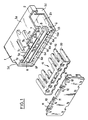
- the shunting device is of the type comprising a housing with at one end an opening for receiving a complementary element, while the other end is intended to receive a strip of connections and is characterized in that the housing has in its bottom a partition pierced by two series of channels, the strip of connections being constituted by a blank which is a good conductor of electricity cut and folded substantially in a U, and to present wings and a core, tongues parallel and perpendicular to the core of the U being cut out in said wings, a cover provided with locking means conjugated with corresponding means of the housing being provided for locking the strip of connections against the partition by bearing against the external face of the core of said strip of connections.
- the strip of connections comprises a number of tabs on one wing greater than that of the other wing.
- the core of the strip of connections comprises straddling the fold lines of the wings, openings thus facilitating the cutting of the strip of connections.
- the device shown in the figures comprises a box 1 formed of a body having a generally parallelepiped shape with four sides 1 a , 1 b , 1 c and 1 d and one face of which has an opening intended to receive a connector, not shown, and provided with a series of female organs connected to suitable circuits.
- the bottom of the housing 1 is closed by a perforated partition 5 comprising on its part adjacent to the side 1 b seven channels 6 to 6 f , while the part of said partition 5 adjacent to the side 1 a comprises six channels 7 to 7 e , three large openings 8 being provided in the intermediate part.
- the case 1 is completed by a cover 10 comprising tabs 11 pierced with a central opening 12 and intended to cooperate with lugs 13 provided in the body 1 and each provided with a ramp 13 a so that when the cover is put in place, the tabs 11 cooperate with said lugs, elastically deform by bearing against the ramps 13 a and then come to cap said lugs which engage in the openings 12 to ensure the locking of said cover on the body.
- the body 1 is intended to receive a strip of connections 15 which is cut from a sheet of sheet metal which is a good conductor of electricity and has a generally rectangular shape with two short sides 16 and 17 and two large sides 18 and 21.
- the tongues 19 and 20 form between them a central strip 30 in which are cut aligned perpendicular to the sides 16 and 17 of the openings 22 and 23.
- In the strip 30 are cut openings 24 and 25 which are aligned and extend perpendicular to the sides 16 and 17.
- the strip of connections is folded in a U along two lines 26 and 28, the first passing through the median plane of the openings 22 and the second, through the median plane of the openings 24 and 25.
- the tongues are cut in the wings of the U, while the core is formed by the band 30.
- connection strip is intended to be engaged in the housing 1, the tongues 20 to 20 f being inserted into the channels 6 to 6 f while the tongues 19 to 19 e penetrate into the channels 7 to 7 e .
- the strip of connections 15 can be cut in different ways depending on the electrical connections to be made.
- the strip 15 is cut along a line passing along the edge of the tongue 19 b through the opening 23, the opening 25 and along the tongue 20 d the part of the strip situated between the openings 25 and the part situated between the tongues 19 c and 19 b being eliminated.
- Figure 4 shows a configuration similar to that of Figure 3 but in which only the part between the opening 23 and the side between the tongues 19 c and 19 b is deleted.
- the strip is cut into three sections, the first comprising the tongues 19, 19 a , 20 and 20 a , the second the tongues 19 b , 19 c and 20 b , 20 c and 20 d and finally , the third tabs 19 e , 19 d and 20 f , 20 e .
- the strip is cut, on the one hand, along the lines 26 and 28 and, on the other hand, along the tongues 19 b and 20 b .
- the housing 1 is intended to receive a housing element engaged by the opening 2 and furnished with female contact members which engage on the tongues 19 and 20 so, from a conductor connected to a source d 'food, to make derivations without having to make splices.
Landscapes
- Connector Housings Or Holding Contact Members (AREA)
- Coupling Device And Connection With Printed Circuit (AREA)
Applications Claiming Priority (2)
| Application Number | Priority Date | Filing Date | Title |
|---|---|---|---|
| FR8910602A FR2650707B1 (fr) | 1989-08-07 | 1989-08-07 | Dispositif de shuntage pour faisceaux de conducteurs electriques |
| FR8910602 | 1989-08-07 |
Publications (1)
| Publication Number | Publication Date |
|---|---|
| EP0412874A1 true EP0412874A1 (de) | 1991-02-13 |
Family
ID=9384529
Family Applications (1)
| Application Number | Title | Priority Date | Filing Date |
|---|---|---|---|
| EP90402170A Withdrawn EP0412874A1 (de) | 1989-08-07 | 1990-07-27 | Nebenschlusseinrichtung für Bündel von elektrischen Leitern |
Country Status (3)
| Country | Link |
|---|---|
| US (1) | US5000699A (de) |
| EP (1) | EP0412874A1 (de) |
| FR (1) | FR2650707B1 (de) |
Cited By (2)
| Publication number | Priority date | Publication date | Assignee | Title |
|---|---|---|---|---|
| EP2393160A1 (de) * | 2010-06-02 | 2011-12-07 | Weidmüller Interface GmbH & Co. KG | Rangierklemme in Etagenbauform |
| EP2806507A4 (de) * | 2012-01-16 | 2015-09-09 | Sumitomo Wiring Systems | Kabelbaum und verfahren zur befestigung eines steckersatzes |
Families Citing this family (39)
| Publication number | Priority date | Publication date | Assignee | Title |
|---|---|---|---|---|
| GB2233164A (en) * | 1989-05-24 | 1991-01-02 | Cinch Connectors Ltd | Selective shorting of plug pins/socket contacts in an electrical connector |
| JPH0382584U (de) * | 1989-12-14 | 1991-08-22 | ||
| JPH0749750Y2 (ja) * | 1990-06-27 | 1995-11-13 | 矢崎総業株式会社 | 分岐回路構成体 |
| US5201667A (en) * | 1990-06-27 | 1993-04-13 | Yazaki Corporation | Branch circuit structure |
| JP2563707Y2 (ja) * | 1990-08-07 | 1998-02-25 | 矢崎総業株式会社 | コネクタ |
| US5062805A (en) * | 1990-11-27 | 1991-11-05 | Pan-International Industrial Corp. | Structure of cable connector for matching with IC mounting seat |
| FR2693318B1 (fr) * | 1992-07-03 | 1994-11-18 | Telemecanique | Barrette de connexion électrique de bornes. |
| JP2903918B2 (ja) * | 1992-12-09 | 1999-06-14 | 住友電装株式会社 | ジョイントコネクタ |
| US5609493A (en) * | 1995-03-16 | 1997-03-11 | Hon Hai Precision Ind. Co., Ltd. | Device for short-circuiting for use with connector |
| US5816851A (en) * | 1995-03-16 | 1998-10-06 | Hon Hai Precision Ind. Co., Ltd. | Device for short-circuiting for use with connector |
| US5788519A (en) * | 1995-05-02 | 1998-08-04 | Yazaki Corporation | Waterproof grounding connector and method of assembling same |
| DE19834473B4 (de) * | 1997-07-31 | 2012-09-27 | The Whitaker Corp. | Elektrischer Steckverbinder mit Kurzschluß-Codierung |
| DE19733328A1 (de) * | 1997-08-01 | 1999-02-04 | Whitaker Corp | Elektrischer Steckverbinder |
| JP3681881B2 (ja) * | 1998-01-29 | 2005-08-10 | 菱星電装株式会社 | ジョイントコネクタ |
| US6431880B1 (en) * | 1998-06-22 | 2002-08-13 | Cooper Technologies | Modular terminal fuse block |
| US6227913B1 (en) * | 1998-06-22 | 2001-05-08 | Cooper Technologies Company | Fuse bus member and connector assembly |
| US6322400B1 (en) * | 1999-03-26 | 2001-11-27 | Marconi Communications, Inc. | Battery termination panel |
| DE60026234T2 (de) * | 1999-04-13 | 2006-12-14 | Sumitomo Wiring Systems, Ltd., Yokkaichi | Verbinder |
| DE60027953T2 (de) * | 1999-04-13 | 2007-04-19 | Sumitomo Wiring Systems, Ltd., Yokkaichi | Wasserdichter Verbinder für elektrische Anschlusskontakte |
| JP2001016744A (ja) * | 1999-06-23 | 2001-01-19 | Harness Syst Tech Res Ltd | 電線の接続構造 |
| JP3854458B2 (ja) * | 2000-10-20 | 2006-12-06 | 矢崎総業株式会社 | 端子金具と端子金具の組立方法 |
| AU2002239936A1 (en) * | 2001-02-05 | 2002-08-19 | Array Connector Corporation | Subminiature electrical connector multi-pin grounding/discrete circuit bussing module and integral connector backshell |
| US6666713B1 (en) * | 2002-07-19 | 2003-12-23 | Ronald D. Norvelle | Ganged receptacle fixture apparatus |
| DE102004034396B4 (de) * | 2003-07-17 | 2011-12-22 | Autonetworks Technologies, Ltd. | Verbindungsteil und Verbindungsstecker für einen Kabelbaum |
| JP4238763B2 (ja) * | 2004-03-30 | 2009-03-18 | 住友電装株式会社 | 電気接続箱 |
| DE102004018554B4 (de) * | 2004-04-14 | 2018-09-27 | Wago Verwaltungsgesellschaft Mbh | Brücker für elektrische Klemmen |
| US20080318467A1 (en) * | 2007-06-19 | 2008-12-25 | Denomme Gary M | Relay receptacle shorting plug |
| EP2824731B1 (de) * | 2007-07-16 | 2017-10-04 | LG Chem, Ltd. | Elektrisches Verbindungselement für Sekundärbatterie |
| CN101854005B (zh) * | 2009-04-03 | 2012-05-30 | 胡连精密股份有限公司 | 回路连接器 |
| JP5612831B2 (ja) * | 2009-05-20 | 2014-10-22 | モレックス インコーポレイテドMolex Incorporated | ループコネクタ及び閉回路形成コネクタ |
| CN102834987B (zh) * | 2010-03-25 | 2015-04-15 | 矢崎总业株式会社 | 接头连接器和用于识别接头连接器中的汇流条图案的方法 |
| GB201204866D0 (en) * | 2012-03-20 | 2012-05-02 | Trw Ltd | Fork type electrical connector |
| JP6141612B2 (ja) * | 2012-09-21 | 2017-06-07 | 矢崎総業株式会社 | コネクタ |
| JP6722386B2 (ja) | 2017-01-06 | 2020-07-15 | 株式会社オートネットワーク技術研究所 | ジョイントコネクタ |
| JP6790838B2 (ja) * | 2017-01-06 | 2020-11-25 | 株式会社オートネットワーク技術研究所 | コネクタ |
| DE202017103748U1 (de) * | 2017-06-23 | 2018-09-26 | Weidmüller Interface GmbH & Co. KG | Anschlussvorrichtung mit veränderlicher elektrischer Verbindung zwischen Leiteranschlüssen |
| JP7054457B2 (ja) * | 2019-01-31 | 2022-04-14 | 住友電装株式会社 | ジョイントコネクタ及びバスバー |
| JP7088110B2 (ja) * | 2019-03-28 | 2022-06-21 | 株式会社オートネットワーク技術研究所 | ジョイントコネクタ |
| JP7753286B2 (ja) * | 2023-04-26 | 2025-10-14 | 矢崎総業株式会社 | コネクタ製造装置 |
Citations (2)
| Publication number | Priority date | Publication date | Assignee | Title |
|---|---|---|---|---|
| US3611251A (en) * | 1969-12-18 | 1971-10-05 | Robert Downhill | Electrical connector |
| US4090667A (en) * | 1977-05-13 | 1978-05-23 | Aries Electronics, Inc. | Universally programmable shorting plug for an integrated circuit socket |
Family Cites Families (8)
| Publication number | Priority date | Publication date | Assignee | Title |
|---|---|---|---|---|
| US2901526A (en) * | 1954-05-26 | 1959-08-25 | Union Carbide Corp | Battery connector |
| US4089041A (en) * | 1975-08-07 | 1978-05-09 | Amp Incorporated | Circuit programming device |
| US4019094A (en) * | 1975-12-19 | 1977-04-19 | General Electric Company | Static control shorting clip for semiconductor package |
| US4401353A (en) * | 1981-08-10 | 1983-08-30 | Augat Inc. | Programmable plug |
| BE895437A (nl) * | 1982-12-22 | 1983-06-22 | Bell Telephone Mfg | Elektrisch geleidende inrichting |
| US4552423A (en) * | 1984-03-30 | 1985-11-12 | Amp Incorporated | Shunted electrical connectors |
| US4643507A (en) * | 1985-04-25 | 1987-02-17 | Amp Incorporated | Electrical terminal with wire receiving slot |
| US4897047A (en) * | 1988-08-10 | 1990-01-30 | Amp Incorporated | Electrically and mechanically programmable electrical apparatus |
-
1989
- 1989-08-07 FR FR8910602A patent/FR2650707B1/fr not_active Expired - Lifetime
-
1990
- 1990-06-26 US US07/543,367 patent/US5000699A/en not_active Expired - Fee Related
- 1990-07-27 EP EP90402170A patent/EP0412874A1/de not_active Withdrawn
Patent Citations (2)
| Publication number | Priority date | Publication date | Assignee | Title |
|---|---|---|---|---|
| US3611251A (en) * | 1969-12-18 | 1971-10-05 | Robert Downhill | Electrical connector |
| US4090667A (en) * | 1977-05-13 | 1978-05-23 | Aries Electronics, Inc. | Universally programmable shorting plug for an integrated circuit socket |
Cited By (2)
| Publication number | Priority date | Publication date | Assignee | Title |
|---|---|---|---|---|
| EP2393160A1 (de) * | 2010-06-02 | 2011-12-07 | Weidmüller Interface GmbH & Co. KG | Rangierklemme in Etagenbauform |
| EP2806507A4 (de) * | 2012-01-16 | 2015-09-09 | Sumitomo Wiring Systems | Kabelbaum und verfahren zur befestigung eines steckersatzes |
Also Published As
| Publication number | Publication date |
|---|---|
| FR2650707B1 (fr) | 1991-10-11 |
| FR2650707A1 (fr) | 1991-02-08 |
| US5000699A (en) | 1991-03-19 |
Similar Documents
| Publication | Publication Date | Title |
|---|---|---|
| FR2650707A1 (fr) | Dispositif de shuntage pour faisceaux de conducteurs electriques | |
| EP0735629B1 (de) | Vorrichtung für die Verbindung von elektrischen Leitungsdrähten und Anschlussblock ausgerüstet mit obiger Vorrichtung | |
| EP0084338B1 (de) | Behälter für elektrochemische Batterien | |
| FR2666933A1 (fr) | Element de liaison electrique de deux conducteurs electriques et connecteur de derivation utilisant un tel element. | |
| FR2791309A1 (fr) | Garniture de pavillon de vehicule automobile | |
| EP0681345A1 (de) | Hermaphroditisches elektrisches Kontaktelement | |
| FR2750812A1 (fr) | Motoreducteur avec plaque porte-lamelles | |
| EP0427615A1 (de) | Elektrischer Kontaktstift und entsprechendes Gehäuse für elektrische Anschlüsse | |
| EP0292394A1 (de) | Elektrische Verbindung | |
| EP0342077A1 (de) | Kurzschliessungseinrichtung für elektrische Steckverbinder | |
| EP1091380B1 (de) | Anordnung von Modulen zur Bildung von Sicherungskasten | |
| EP0859432A1 (de) | Weibliches elektrisches Kontaktorgan | |
| EP0581638B1 (de) | Elektrischer Verbinder | |
| EP0207841A1 (de) | Montieren von elektrischen Verbindungselementen | |
| FR2799890A1 (fr) | Connecteur comportant des contacts shuntables et configurables | |
| EP0635902A1 (de) | Anschlusselement und elektrischer Verbindermodul | |
| EP0860901B1 (de) | Gehäuse für elektrischen Gerät und elektrische Vorrichtung mit einem solchen Gehäuse | |
| EP0643453B1 (de) | Elektrischer Verbinder für zwei Flachkontakte | |
| EP0259199B1 (de) | Elektrische Verbindungsanordnung für einen Lautsprechermotor | |
| FR2802718A1 (fr) | Boite a fusibles pour vehicules automobiles | |
| FR2650706A1 (fr) | Dispositif de raccordement d'un conducteur de derivation a un conducteur principal isole | |
| FR2618952A1 (fr) | Boitier de connexions electriques | |
| FR2729508A1 (fr) | Element de boitier d'un connecteur electrique | |
| EP0780934B1 (de) | Kurzschliesseinrichtung für elektrischen Kontakte in Reihe | |
| FR2780205A1 (fr) | Dispositif de liaison d'un conducteur electrique de derivation sur un conducteur principal |
Legal Events
| Date | Code | Title | Description |
|---|---|---|---|
| PUAI | Public reference made under article 153(3) epc to a published international application that has entered the european phase |
Free format text: ORIGINAL CODE: 0009012 |
|
| AK | Designated contracting states |
Kind code of ref document: A1 Designated state(s): DE ES GB IT SE |
|
| 17P | Request for examination filed |
Effective date: 19910102 |
|
| 17Q | First examination report despatched |
Effective date: 19920130 |
|
| STAA | Information on the status of an ep patent application or granted ep patent |
Free format text: STATUS: THE APPLICATION IS DEEMED TO BE WITHDRAWN |
|
| 18D | Application deemed to be withdrawn |
Effective date: 19920616 |