EP0413070A2 - Gemüseschneidvorrichtung - Google Patents
Gemüseschneidvorrichtung Download PDFInfo
- Publication number
- EP0413070A2 EP0413070A2 EP89312685A EP89312685A EP0413070A2 EP 0413070 A2 EP0413070 A2 EP 0413070A2 EP 89312685 A EP89312685 A EP 89312685A EP 89312685 A EP89312685 A EP 89312685A EP 0413070 A2 EP0413070 A2 EP 0413070A2
- Authority
- EP
- European Patent Office
- Prior art keywords
- impeller
- bearing
- hub
- tube
- bevel gear
- Prior art date
- Legal status (The legal status is an assumption and is not a legal conclusion. Google has not performed a legal analysis and makes no representation as to the accuracy of the status listed.)
- Withdrawn
Links
- 235000013311 vegetables Nutrition 0.000 title claims abstract description 17
- 239000000356 contaminant Substances 0.000 claims abstract description 8
- XLYOFNOQVPJJNP-UHFFFAOYSA-N water Substances O XLYOFNOQVPJJNP-UHFFFAOYSA-N 0.000 claims abstract description 7
- 125000006850 spacer group Chemical group 0.000 claims description 10
- 238000006073 displacement reaction Methods 0.000 claims 3
- 230000032258 transport Effects 0.000 abstract 1
- 235000002595 Solanum tuberosum Nutrition 0.000 description 20
- 244000061456 Solanum tuberosum Species 0.000 description 20
- 239000004519 grease Substances 0.000 description 14
- 235000012015 potatoes Nutrition 0.000 description 11
- 235000012773 waffles Nutrition 0.000 description 7
- 238000012423 maintenance Methods 0.000 description 3
- 238000012986 modification Methods 0.000 description 3
- 230000004048 modification Effects 0.000 description 3
- 235000013606 potato chips Nutrition 0.000 description 3
- 230000004888 barrier function Effects 0.000 description 2
- 230000002457 bidirectional effect Effects 0.000 description 2
- 230000015556 catabolic process Effects 0.000 description 2
- 238000011109 contamination Methods 0.000 description 2
- 238000006731 degradation reaction Methods 0.000 description 2
- 235000013305 food Nutrition 0.000 description 2
- 230000001050 lubricating effect Effects 0.000 description 2
- 239000007787 solid Substances 0.000 description 2
- 239000011343 solid material Substances 0.000 description 2
- 238000004140 cleaning Methods 0.000 description 1
- 239000000428 dust Substances 0.000 description 1
- 239000000463 material Substances 0.000 description 1
- 239000011236 particulate material Substances 0.000 description 1
- 239000013618 particulate matter Substances 0.000 description 1
- 230000001681 protective effect Effects 0.000 description 1
- 230000000717 retained effect Effects 0.000 description 1
- 238000005096 rolling process Methods 0.000 description 1
- 238000007789 sealing Methods 0.000 description 1
Images

Classifications
-
- B—PERFORMING OPERATIONS; TRANSPORTING
- B26—HAND CUTTING TOOLS; CUTTING; SEVERING
- B26D—CUTTING; DETAILS COMMON TO MACHINES FOR PERFORATING, PUNCHING, CUTTING-OUT, STAMPING-OUT OR SEVERING
- B26D7/00—Details of apparatus for cutting, cutting-out, stamping-out, punching, perforating, or severing by means other than cutting
- B26D7/06—Arrangements for feeding or delivering work of other than sheet, web, or filamentary form
-
- Y—GENERAL TAGGING OF NEW TECHNOLOGICAL DEVELOPMENTS; GENERAL TAGGING OF CROSS-SECTIONAL TECHNOLOGIES SPANNING OVER SEVERAL SECTIONS OF THE IPC; TECHNICAL SUBJECTS COVERED BY FORMER USPC CROSS-REFERENCE ART COLLECTIONS [XRACs] AND DIGESTS
- Y10—TECHNICAL SUBJECTS COVERED BY FORMER USPC
- Y10T—TECHNICAL SUBJECTS COVERED BY FORMER US CLASSIFICATION
- Y10T83/00—Cutting
- Y10T83/647—With means to convey work relative to tool station
- Y10T83/6473—Centrifugal feed to tangential tool [e.g., "Beria" type]
-
- Y—GENERAL TAGGING OF NEW TECHNOLOGICAL DEVELOPMENTS; GENERAL TAGGING OF CROSS-SECTIONAL TECHNOLOGIES SPANNING OVER SEVERAL SECTIONS OF THE IPC; TECHNICAL SUBJECTS COVERED BY FORMER USPC CROSS-REFERENCE ART COLLECTIONS [XRACs] AND DIGESTS
- Y10—TECHNICAL SUBJECTS COVERED BY FORMER USPC
- Y10T—TECHNICAL SUBJECTS COVERED BY FORMER US CLASSIFICATION
- Y10T83/00—Cutting
- Y10T83/647—With means to convey work relative to tool station
- Y10T83/6476—Including means to move work from one tool station to another
- Y10T83/6478—Tool stations angularly related
- Y10T83/6481—With static tool
-
- Y—GENERAL TAGGING OF NEW TECHNOLOGICAL DEVELOPMENTS; GENERAL TAGGING OF CROSS-SECTIONAL TECHNOLOGIES SPANNING OVER SEVERAL SECTIONS OF THE IPC; TECHNICAL SUBJECTS COVERED BY FORMER USPC CROSS-REFERENCE ART COLLECTIONS [XRACs] AND DIGESTS
- Y10—TECHNICAL SUBJECTS COVERED BY FORMER USPC
- Y10T—TECHNICAL SUBJECTS COVERED BY FORMER US CLASSIFICATION
- Y10T83/00—Cutting
- Y10T83/929—Tool or tool with support
- Y10T83/9493—Stationary cutter
Definitions
- the present invention relates generally to food processing and, in particular, to improvements in a machine used to slice vegetables and more particularly to a machine to slice potatoes to make waffle cut potato chips.
- a waffle cut potato chip characteristically has longitudinal ridges and grooves formed in both cut surfaces to give it a corrugated shape.
- the grooves on one surface are perpendicular to the ridges and grooves on the opposite surface.
- the grooves are sufficiently deep such that the grooves of one cut surface intersect those of the other cut surface to form a grid of openings in the chip.
- the only known commercially available potato slicing machine for making waffle cut potato chips is substantially like that shown in Urschel, U.S. Patent Nos. 3,139,127 and 3,139,130, manufactured by Urschel Laboratories, Inc., Valparaiso, Indiana as model "CCL”.
- whole potatoes are received by a central rotating carriage or impeller hub and fed outwardly by centrifugal force into one of several radial guides or impeller tubes which simultaneously rotate and direct the potatoes to a stationary cutting assembly surrounding the impeller hub.
- the cutting assembly includes a plurality of circumferentially spaced corrugated knives that project into the path of the orbiting potatoes to cut away thin slices of the potatoes, shunting the slices tangentially away from the cutting assembly as they are cut.
- Means are provided to cause the impeller tubes, and hence the potatoes carried therein, to rotate 90 degrees within the impeller hub in between successive cuts of the potato.
- the corrugated knives slice the potatoes into thin potato slices having ridges and grooves on one side that are perpendicular to the ridges and grooves on the other side.
- the impeller tubes rotate about the impeller hub in order to cause the potatoes to rotate 90 degrees between each successive slice.
- a bearing is located between the impeller hub and the impeller tube to ensure smooth rotation.
- This bearing is susceptible to being contaminated by water and solid materials which flow between the impeller tube and the impeller hub.
- the bearings are about six inches in diameter are very expensive to replace. The contamination of these bearings causes them to have a life of approximately 250 hours.
- the bearings currently are lubricated by a human consumable vegetable type grease. Even with proper maintenance and greasing schedules, the grease is insufficient to keep the moisture and contaminants from destroying the bearings.
- Still another object of this invention is to improve the performance and reduce the maintenance costs of waffle cut slicing apparatus having a central hub which rotates about a vertical axis and at least one rotatably connected impeller tube which rotates about a horizontal axis aligned radially with respect to the hub's vertical axis.
- a framework holds a stationary knife-supporting member about a rotating impeller assembly.
- the impeller assembly is comprised of an impeller hub having a central, vertical opening into which a product to be sliced is fed.
- the impeller hub has a plurality of tubular extensions extending radially outward from the central portion of the impeller hub.
- An impeller tube is centrally located within each tubular extension of the impeller hub.
- An impeller bevel gear is attached to each impeller tube by suitable fastening means.
- a bearing riding on each tubular extension has an inner race which contacts the tubular extension of the impeller hub. The outer race of the bearing rests against and rotatably supports the impeller bevel gear.
- a snap ring fitting in a groove of the tubular extension of the impeller hub prevents the bearing from being laterally displaced.
- a spacer of the same thickness as the snap ring entraps the outer race of the bearing between the impeller tube and the impeller bevel gear.
- a first seal is located in a recess of the impeller tube outboard of the snap ring and the spacer and effectuates a seal between the impeller tube and the tubular extension of the impeller hub.
- a second seal fits in a recess of the impeller bevel gear and seals the impeller bevel gear to the tubular extension of the impeller hub inboard of the bearing.
- a drain hole is provided in the impeller tube to sling any water which may come between the impeller tube and the impeller hub out away from the first seal.
- a grease fitting is provided in the impeller bevel gear to allow grease to be forced into a cavity located adjacent to the bearing to lubricate the bearing.
- the first seal and second seal prevent the grease from coming outside the impeller tube and impeller bevel gear assembly.
- the tubular extension of the impeller hub has a first step for receiving the bearing and a second step for receiving the second seal.
- the product to be sliced typically a potato
- the impeller hub is rotated in a circular manner by a drive means centrally located to the impeller hub.
- the potato is forced outwardly by centrifugal force into the opening in the center of one of the impeller tubes.
- Serrated toothed members inside the impeller tube prevents the potato from rolling in the tube and from working back toward the center of the impeller hub.
- the impeller bevel gears rest in tooth-to-tooth relationship with a fixed bevel gear which is attached to the frame.
- the impeller bevel gear rotates the impeller tube such that the surface of the potato being sliced is rotated ninety degrees relative to the preceding slice. In this manner waffle cut potatoes having corrugated cuts on one surface and corrugated cuts on the second surface at ninety degrees to the first surface are formed.
- FIG. 1 and FIG. 2 show the current or prior art embodiment of the Urschel apparatus used to produce waffle cut potatoes.
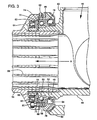
- the present invention shown in FIG. 3, is an improvement over this current machine and a detailed description will be given of the differences between the Urschel device and the present invention.
- a fixed knife support 2 is located on a frame (not shown) and holds a plurality of knives 4.
- An impeller assembly 10 is located centrally within the periphery of surrounding knife support 2.
- the impeller assembly includes an impeller hub 12 having a top opening to provide a means to receive the product to be sliced.
- This impeller hub has a plurality of tubular extensions 14 extending radially outward from the impeller hub 12. In the embodiment shown in FIG. 1 there are four tubular extensions which rotate past four knives 4.
- the impeller assembly also includes impeller tubes 16, each located such that its central-most portion is axially within one of the tubular extensions.
- the impeller tube 16 being hollow receives the product to be sliced and displaces the product outwardly under centrifugal force against the knives.
- Each impeller tube 16 is attached to an impeller bevel gear 18 by means of suitable fasteners 20. Captivated between the impeller tube 16 and the impeller bevel gear 18 is a ball bearing 22. These bearings are approximately 6 inches in diameter and typically have an average life of approximately 250 hours in a potato slicing environment.
- FIG. 2 shows the arrangements of the various components that make up the impeller assembly.
- the impeller hub 12 has a tubular extension 14 extending therefrom.
- the impeller tube 16 is attached to the impeller bevel gear 18 by means of a suitable fastener 20.
- the bearing 22 can be seen entrapped between the impeller bevel gear 18 and the tubular extension 14 of the impeller hub 14.
- the tubular extension has a step 30 upon which the inner race of the bearing bears.
- the bearing is retained in a pocket formed between the tubular extension and impeller bevel gear by a snap ring 26 which fits into a groove 32 in the tubular extension of the impeller hub.
- a boss on the impeller tube entraps the outer race of the bearing between the impeller tube and the impeller bevel gear.
- a product P to be sliced is placed into the central opening of the impeller hub 12 generally along the center line marked O in FIG. 1.
- the product P is flung radially outwardly by centrifugal force along arrow B into one of impeller tubes.
- the product eventually ends up in a position P′ (FIG. 1) whereupon it is slicingly engaged by one of the knives 4.
- the impeller hub assembly continues to rotate in the direction of the arrow A by means of a shaft through the frame (not shown). This rotation is in a first plane parallel to the plane of the frame.
- the stationary bevel gear 24 being in engagement with each of the impeller bevel gears 18 would cause the impeller tube 16 to rotate.
- This rotation would cause the product P′ to be rotated 90 degrees between successive slices of the knives 4.
- This rotation of the impeller tube is in a second plane which is perpendicular to the first plane.
- FIG. 3 a vertical cross-section of a portion of the impeller assembly of the present invention is shown.
- the cross-section is taken through one of the tubular extensions of the impeller hub assembly.
- the impeller hub 42 has a vertical opening 44 which receives the product to be sliced.
- a solid floor 46 is immediately below the opening 44 and is attached to a vertical shaft (not shown) which rotates the impeller hub 42.
- This impeller hub is a first member.
- a tubular extension 48 of the impeller hub has a first step 50 and a second step 52.
- the first step is about the circumferential periphery of the tubular extension and is smaller in diameter than the second step 52.
- a groove 54 is machined about the periphery of the first step 50 of the tubular extension of the impeller hub.
- a snap ring 55 fits into groove 54.
- An impeller tube 56 has a hollow tubular end portion that fits inside the tubular extension of the impeller hub.
- the outer diameter of the tubular end portion is slightly less than the inner diameter of the tubular extension.
- the tubular end portion has serrated teeth 58 projecting along the length of the inside thereof. These serrated teeth allow the product to be sliced to progress in the direction of arrow B but prevents the product to be sliced from falling back toward the opening 44.
- Impeller tube 56 has a recess 60 machined about its inside periphery. Recess 60 is manufactured to accommodate a first seal 62. Seal 62 is a smoothlip bidirectional seal.
- the impeller tube also has an open passageway 64 to allow any water which enters between the impeller tube 56 and the tubular extension 48 to exit without creating pressure on seal 62.
- a bearing 66 is restrained on the first step of the tubular extension of the impeller hub and held in place by the snap ring 55.
- Bearing 66 has an outer race 68 and an inner race 70.
- the snap ring 55 bears against one side of the inner race 70, with the other side of race 68 abutting a lip formed by the first step.
- the bearing 66 in the preferred embodiment, is a ball bearing.
- the spacer 72 is a flat circular member having an inside diameter larger in diameter than the outside diameter of the snap ring.
- the bearing races have a first face 74.
- the first face of the inner race of the bearing 66 bears against the snap ring 55 while the first face of the outer race bears against the spacer 72.
- the bearing has a second face 76 opposite the first face 74.
- the second face of the inner race 70 bears against the step of the tubular extension of the impeller hub.
- the second face of the outer race 68 bears against a lip portion of an impeller bevel gear 78.
- Impeller bevel gear 78 is attached to impeller tube 56 by means of suitable fasteners, such as set screws 80.
- Bevel gear 78 is in tooth-to-tooth engagement with a fixed bevel gear 82.
- the fixed bevel gear is attached to the frame (not shown).
- the combination of the impeller tube 56, the impeller bevel gear 78, the spacer 72 and the fasteners 80 constitutes
- a second seal 84 has a surface which rides on the impeller gear 78 and a second surface which contacts the tubular extension 48 of the impeller hub 42 along the second step 52.
- the second seal 84 in the preferred embodiment, is a smoothlip bidirectional seal.
- a grease fitting 86 is threaded into the impeller bevel gear.
- the grease fitting 86 allows grease to be forced into a grease channel 88.
- the grease channel communicates the grease through the bearing and against both the first seal 62 and the second seal 84.
- the grease therefore is captivated between the seals and cannot exit the bearing area to cause contamination of food products.
- a lubricating grade grease which is not rated for human consumption may thus be used to lubricate the bearing. Any moisture which would pass between the impeller tube and the tubular extension of the impeller hub is slung out through opening 64 and cannot contaminate the bearings.
- seal 62 In operation, moisture, particulate matter and contaminants entering the seam between the impeller tube and tubular extension are prevented by seal 62 from contaminating bearing 66.
- the effectiveness of seal 62 as a protective barrier is further enhanced by passageway 64 which allows such moisture and contaminants to be shunted away from the bearing area by centrifugal force and exit the impeller tube. This self-cleaning feature also reduces the tendency of moisture and contaminants to build up pressure adjacent the seal and thereby cause degradation or break down of the seal barrier.
- Seal 84 seals the other side of the bearing and prevents dust, dirt or other contaminants from entering the spacing between the impeller bevel gear and tubular extension and causing degradation of the bearing.
Landscapes
- Life Sciences & Earth Sciences (AREA)
- Forests & Forestry (AREA)
- Engineering & Computer Science (AREA)
- Mechanical Engineering (AREA)
- Preparation Of Fruits And Vegetables (AREA)
Applications Claiming Priority (2)
| Application Number | Priority Date | Filing Date | Title |
|---|---|---|---|
| US07/394,216 US4949612A (en) | 1989-08-15 | 1989-08-15 | Apparatus for slicing vegetables |
| US394216 | 1989-08-15 |
Publications (2)
| Publication Number | Publication Date |
|---|---|
| EP0413070A2 true EP0413070A2 (de) | 1991-02-20 |
| EP0413070A3 EP0413070A3 (en) | 1991-07-10 |
Family
ID=23558035
Family Applications (1)
| Application Number | Title | Priority Date | Filing Date |
|---|---|---|---|
| EP19890312685 Withdrawn EP0413070A3 (en) | 1989-08-15 | 1989-12-06 | Apparatus for slicing vegetables |
Country Status (4)
| Country | Link |
|---|---|
| US (1) | US4949612A (de) |
| EP (1) | EP0413070A3 (de) |
| AU (1) | AU4567789A (de) |
| CA (1) | CA2019595C (de) |
Cited By (1)
| Publication number | Priority date | Publication date | Assignee | Title |
|---|---|---|---|---|
| NL1014889C2 (nl) * | 2000-04-10 | 2001-10-11 | Jasca Food Proc Systems B V | Inrichting voor het snijden van gelede producten. |
Families Citing this family (6)
| Publication number | Priority date | Publication date | Assignee | Title |
|---|---|---|---|---|
| US5385074A (en) * | 1993-02-23 | 1995-01-31 | Cavendish Farms Limited | Apparatus and method for cutting helically shaped potato pieces |
| US6536691B2 (en) | 2001-02-23 | 2003-03-25 | Leprino Foods Company | Apparatus for and method of shredding a product |
| US7559275B1 (en) * | 2005-05-26 | 2009-07-14 | Dole Fresh Vegetables, Inc. | Top and tail trimming system for leafy vegetables |
| JP2011511715A (ja) * | 2008-02-08 | 2011-04-14 | コンアグラ フーヅ ラム ウェストン インコーポレイテッド | 野菜をスライスするための装置および方法 |
| US8549996B2 (en) | 2010-05-28 | 2013-10-08 | Dole Fresh Vegetables, Inc. | System for topping and tailing lettuce heads using a camera-guided servo-controlled water knife |
| EP3860817B1 (de) | 2018-10-03 | 2026-04-15 | Urschel Laboratories, Inc. | Schneidemaschinen und verfahren zum schneiden von produkten |
Family Cites Families (10)
| Publication number | Priority date | Publication date | Assignee | Title |
|---|---|---|---|---|
| US2858176A (en) * | 1956-08-20 | 1958-10-28 | Transall Inc | Bearing mounting and seals therefor |
| FR1208143A (fr) * | 1958-12-08 | 1960-02-22 | Palier étanche pour roulement à billes | |
| US3139127A (en) * | 1959-12-03 | 1964-06-30 | Joe R Urschel | Machine for slicing a food product |
| US3139130A (en) * | 1959-12-03 | 1964-06-30 | Joe R Urschel | Method of slicing food products |
| US3397020A (en) * | 1966-02-16 | 1968-08-13 | Timken Roller Bearing Co | Single row tapered roller bearing |
| US3531168A (en) * | 1968-11-14 | 1970-09-29 | Federal Mogul Corp | Shaft seal transmitting thrust to roller bearing |
| GB1391921A (en) * | 1971-03-29 | 1975-04-23 | Forsheda Ideutveckling Ab | Locking and sealing device |
| US4575265A (en) * | 1980-05-27 | 1986-03-11 | Reliance Electric Company | Seal for shaft bearings |
| US4523503A (en) * | 1983-08-22 | 1985-06-18 | Lamb-Weston, Inc. | Apparatus for making waffle-cut potato |
| SE450851B (sv) * | 1986-01-24 | 1987-08-03 | Skf Mekanprodukter Ab | Anordning for montering av ett lager innefattande tetningar |
-
1989
- 1989-08-15 US US07/394,216 patent/US4949612A/en not_active Expired - Lifetime
- 1989-11-28 AU AU45677/89A patent/AU4567789A/en not_active Abandoned
- 1989-12-06 EP EP19890312685 patent/EP0413070A3/en not_active Withdrawn
-
1990
- 1990-06-22 CA CA002019595A patent/CA2019595C/en not_active Expired - Lifetime
Cited By (1)
| Publication number | Priority date | Publication date | Assignee | Title |
|---|---|---|---|---|
| NL1014889C2 (nl) * | 2000-04-10 | 2001-10-11 | Jasca Food Proc Systems B V | Inrichting voor het snijden van gelede producten. |
Also Published As
| Publication number | Publication date |
|---|---|
| CA2019595A1 (en) | 1991-02-15 |
| CA2019595C (en) | 2001-05-08 |
| EP0413070A3 (en) | 1991-07-10 |
| US4949612A (en) | 1990-08-21 |
| AU4567789A (en) | 1991-02-21 |
Similar Documents
| Publication | Publication Date | Title |
|---|---|---|
| US4604925A (en) | Method and apparatus for slicing produce | |
| EP0759837B1 (de) | Schneidmesser für ein Rotationsgerät zum Schneiden eines Nahrungsmittels und Rotationschneidgerät | |
| US3139130A (en) | Method of slicing food products | |
| US4949612A (en) | Apparatus for slicing vegetables | |
| JP2012166337A (ja) | 食品切断装置 | |
| EP3064108B1 (de) | Modulare lebensmittelverarbeitungs- und -zubereitungsvorrichtung | |
| US20180222075A1 (en) | Water bearing and food cutting assembly | |
| US4216686A (en) | Rotary cutting mechanism | |
| EP3580028B1 (de) | Wasserlager und lebensmittelschneidanordnung | |
| US4677888A (en) | Self-contained machine for simultaneously slicing and perforating muffins prior to packaging | |
| US10363679B2 (en) | Water bearing and food cutting assembly | |
| US2138262A (en) | Cutting machine | |
| US5136908A (en) | Food slicer apparatus and knife therefor | |
| CA1251354A (en) | Cutter and ejector for use in manufacture of licorice bites | |
| CN210791178U (zh) | 一种v型皮带切菜机 | |
| KR102573053B1 (ko) | 식자재 절단장치 | |
| US2934118A (en) | Onion trimming machine | |
| ATE27969T1 (de) | Trommelwurzelschneider. | |
| WO1985000774A1 (en) | Device for slicing in particular processed meats, such as butcher's meat and bacon | |
| KR20220077306A (ko) | 감귤의 자동 슬라이싱 장치 및 시스템 | |
| CN119328840B (zh) | 一种软果皮自动切块装置 | |
| DE19844436C2 (de) | Verfahren und Vorrichtung zum Schneiden von Lebensmittelprodukten | |
| WO1985004833A1 (en) | An apparatus for cutting a block of food into slices | |
| JPS604717Y2 (ja) | パンの複列スライサ− | |
| JPS6348676B2 (de) |
Legal Events
| Date | Code | Title | Description |
|---|---|---|---|
| PUAI | Public reference made under article 153(3) epc to a published international application that has entered the european phase |
Free format text: ORIGINAL CODE: 0009012 |
|
| AK | Designated contracting states |
Kind code of ref document: A2 Designated state(s): AT BE CH DE ES FR GB GR IT LI LU NL SE |
|
| RBV | Designated contracting states (corrected) |
Designated state(s): DE FR GB NL SE |
|
| PUAL | Search report despatched |
Free format text: ORIGINAL CODE: 0009013 |
|
| AK | Designated contracting states |
Kind code of ref document: A3 Designated state(s): AT BE CH DE ES FR GB GR IT LI LU NL SE |
|
| 17P | Request for examination filed |
Effective date: 19920107 |
|
| 17Q | First examination report despatched |
Effective date: 19920907 |
|
| STAA | Information on the status of an ep patent application or granted ep patent |
Free format text: STATUS: THE APPLICATION IS DEEMED TO BE WITHDRAWN |
|
| 18D | Application deemed to be withdrawn |
Effective date: 19930318 |