EP0413083A1 - Support de caoutchouc avec amortissement hydraulique - Google Patents
Support de caoutchouc avec amortissement hydraulique Download PDFInfo
- Publication number
- EP0413083A1 EP0413083A1 EP90103873A EP90103873A EP0413083A1 EP 0413083 A1 EP0413083 A1 EP 0413083A1 EP 90103873 A EP90103873 A EP 90103873A EP 90103873 A EP90103873 A EP 90103873A EP 0413083 A1 EP0413083 A1 EP 0413083A1
- Authority
- EP
- European Patent Office
- Prior art keywords
- support
- end wall
- suspension
- stop surface
- rubber
- Prior art date
- Legal status (The legal status is an assumption and is not a legal conclusion. Google has not performed a legal analysis and makes no representation as to the accuracy of the status listed.)
- Granted
Links
- 238000013016 damping Methods 0.000 title claims abstract description 9
- 239000000725 suspension Substances 0.000 claims abstract description 20
- 238000002485 combustion reaction Methods 0.000 claims description 2
- 238000002955 isolation Methods 0.000 description 4
- 239000011324 bead Substances 0.000 description 2
- 238000006073 displacement reaction Methods 0.000 description 2
- 239000007788 liquid Substances 0.000 description 2
- 229910000831 Steel Inorganic materials 0.000 description 1
- 230000005540 biological transmission Effects 0.000 description 1
- 230000000903 blocking effect Effects 0.000 description 1
- 239000012530 fluid Substances 0.000 description 1
- 239000002184 metal Substances 0.000 description 1
- 238000000034 method Methods 0.000 description 1
- 230000007935 neutral effect Effects 0.000 description 1
- 238000005192 partition Methods 0.000 description 1
- 230000036316 preload Effects 0.000 description 1
- 230000003068 static effect Effects 0.000 description 1
- 239000010959 steel Substances 0.000 description 1
- 230000001360 synchronised effect Effects 0.000 description 1
Images
Classifications
-
- F—MECHANICAL ENGINEERING; LIGHTING; HEATING; WEAPONS; BLASTING
- F16—ENGINEERING ELEMENTS AND UNITS; GENERAL MEASURES FOR PRODUCING AND MAINTAINING EFFECTIVE FUNCTIONING OF MACHINES OR INSTALLATIONS; THERMAL INSULATION IN GENERAL
- F16F—SPRINGS; SHOCK-ABSORBERS; MEANS FOR DAMPING VIBRATION
- F16F13/00—Units comprising springs of the non-fluid type as well as vibration-dampers, shock-absorbers, or fluid springs
- F16F13/04—Units comprising springs of the non-fluid type as well as vibration-dampers, shock-absorbers, or fluid springs comprising both a plastics spring and a damper, e.g. a friction damper
- F16F13/26—Units comprising springs of the non-fluid type as well as vibration-dampers, shock-absorbers, or fluid springs comprising both a plastics spring and a damper, e.g. a friction damper characterised by adjusting or regulating devices responsive to exterior conditions
-
- F—MECHANICAL ENGINEERING; LIGHTING; HEATING; WEAPONS; BLASTING
- F16—ENGINEERING ELEMENTS AND UNITS; GENERAL MEASURES FOR PRODUCING AND MAINTAINING EFFECTIVE FUNCTIONING OF MACHINES OR INSTALLATIONS; THERMAL INSULATION IN GENERAL
- F16F—SPRINGS; SHOCK-ABSORBERS; MEANS FOR DAMPING VIBRATION
- F16F13/00—Units comprising springs of the non-fluid type as well as vibration-dampers, shock-absorbers, or fluid springs
- F16F13/04—Units comprising springs of the non-fluid type as well as vibration-dampers, shock-absorbers, or fluid springs comprising both a plastics spring and a damper, e.g. a friction damper
- F16F13/06—Units comprising springs of the non-fluid type as well as vibration-dampers, shock-absorbers, or fluid springs comprising both a plastics spring and a damper, e.g. a friction damper the damper being a fluid damper, e.g. the plastics spring not forming a part of the wall of the fluid chamber of the damper
- F16F13/08—Units comprising springs of the non-fluid type as well as vibration-dampers, shock-absorbers, or fluid springs comprising both a plastics spring and a damper, e.g. a friction damper the damper being a fluid damper, e.g. the plastics spring not forming a part of the wall of the fluid chamber of the damper the plastics spring forming at least a part of the wall of the fluid chamber of the damper
- F16F13/18—Units comprising springs of the non-fluid type as well as vibration-dampers, shock-absorbers, or fluid springs comprising both a plastics spring and a damper, e.g. a friction damper the damper being a fluid damper, e.g. the plastics spring not forming a part of the wall of the fluid chamber of the damper the plastics spring forming at least a part of the wall of the fluid chamber of the damper characterised by the location or the shape of the equilibration chamber, e.g. the equilibration chamber, surrounding the plastics spring or being annular
-
- F—MECHANICAL ENGINEERING; LIGHTING; HEATING; WEAPONS; BLASTING
- F16—ENGINEERING ELEMENTS AND UNITS; GENERAL MEASURES FOR PRODUCING AND MAINTAINING EFFECTIVE FUNCTIONING OF MACHINES OR INSTALLATIONS; THERMAL INSULATION IN GENERAL
- F16F—SPRINGS; SHOCK-ABSORBERS; MEANS FOR DAMPING VIBRATION
- F16F13/00—Units comprising springs of the non-fluid type as well as vibration-dampers, shock-absorbers, or fluid springs
- F16F13/04—Units comprising springs of the non-fluid type as well as vibration-dampers, shock-absorbers, or fluid springs comprising both a plastics spring and a damper, e.g. a friction damper
- F16F13/06—Units comprising springs of the non-fluid type as well as vibration-dampers, shock-absorbers, or fluid springs comprising both a plastics spring and a damper, e.g. a friction damper the damper being a fluid damper, e.g. the plastics spring not forming a part of the wall of the fluid chamber of the damper
- F16F13/20—Units comprising springs of the non-fluid type as well as vibration-dampers, shock-absorbers, or fluid springs comprising both a plastics spring and a damper, e.g. a friction damper the damper being a fluid damper, e.g. the plastics spring not forming a part of the wall of the fluid chamber of the damper characterised by comprising also a pneumatic spring
Definitions
- the invention relates to a rubber bearing according to the preamble of claim 1.
- Such a rubber bearing is known from DE-OS 34 47 950.
- the elastic suspension of the resilient end wall is clamped at the edge in a partition, which in turn is resiliently mounted in the direction of the working area.
- the end wall is delimited on the back by a cavity and the bottom of the cavity also forms the stop surface. With this, the back of the end wall is brought into engagement when evacuating acoustically disturbing vibrations by evacuating the cavity. The isolation of acoustically disturbing vibrations is unsatisfactory.
- the invention has for its object to further develop such a rubber bearing such that there is a substantially improved isolation of acoustically disturbing vibrations.
- Claim 2 relates to an advantageous use of the rubber bearing according to the invention.
- the suspension is connected directly to the support, it being provided that the stop surface is assigned to the support in a rigid manner and the connecting wall is freely movable when vibrations are introduced which are disturbing acoustically.
- the end wall Due to the direct mutual connection between the suspension and the support, the end wall is mounted in a position which is assigned to the work area in a substantially constant manner.
- the pressure waves induced when acoustically disturbing vibrations are introduced into the support within the working area are therefore able to reach the end wall after a largely identical running time, which favors the occurrence of synchronous evasive movements of the end wall. This significantly improves the isolation of acoustically disturbing vibrations.
- the direct mutual connection between the suspension and the support makes it possible to increase the replacement piston area of the end wall to a significant extent. This can easily reach a value that exceeds the size of the replacement piston surface of the spring element and the support.
- the resulting evasive movement of the end wall when the support is deflected is correspondingly reduced in amplitude, which makes a significant contribution to compensating well for the pressure changes generated in the work space on the introduction of acoustically disturbing vibrations.
- the end wall is freely movable when appropriate vibrations are introduced, for example with the aid of Sensors that are attached directly to the sound source that excites the vibrations.
- Appropriate means are known and are not the subject of the present invention.
- the rubber mount according to the invention is particularly well suited for use in mounting an internal combustion engine in a motor vehicle.
- the signal required to control the relative mobility of the end wall can be found in the ignition signal, which makes the use of a separate sensor unnecessary.
- the rubber mount according to the invention is provided with a hydraulic damping device with a view to suppressing resonance-induced vibrations of the mounted machine part.
- a hydraulic damping device with a view to suppressing resonance-induced vibrations of the mounted machine part.
- the known actuators can be used to control the relative mobility of the boundary wall, for example those which are actuated mechanically, hydraulically or pneumatically.
- the use of mixed forms is also possible.
- the end wall in the central area is designed to be completely non-deformable and consists, for example, of metal.
- the suspension as such which surrounds the end wall at the edge and is in turn connected to the support bearing in the region of the outer circumference, can be elastically deformed, for example via a bead accommodated in a groove adapted to the cross section.
- the extent of the stop surface is limited to the area of the suspension.
- the mutual distance between the suspension and the stop surface in the neutral, unconnected state is expediently dimensioned such that a radially inwardly increasing value results in the direction of movement.
- the achievement of a uniform movement sequence in the suspension during the intended use is hereby significantly favored.
- the suspension expediently has an increasing thickness in the direction of movement in the radial direction inwards.
- the feature is of particular importance with regard to ensuring that the suspension is subjected to even flexing stress over its entire circumference and thus for the service life.
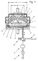
- the rubber bearing shown in Figure 1 is provided with a hydraulic damping device. It comprises a working space 1 which is delimited by a rubber-elastic spring element 2, a support 3, a support 4 and a flexible end wall 5 which is flexible in the direction of the working space 1 and which is provided with an elastic suspension and can be applied to a stop surface 6 depending on predetermined parameters is.
- the suspension 11 of the end wall 5 is directly connected to the support 4, it being provided that the stop surface 6 is assigned to the support 4 in a rigid manner and the end wall 5 is freely movable when acoustically disturbing vibrations are introduced.
- the working space 1 is connected to a compensating space 7 by a damping opening 8 in the form of a channel. Both the working space 1 and the damping opening 8 and the compensation space 7 are completely filled with a hydraulic fluid.
- the equalization chamber 7 is closed off from the outside by an easily deformable bellows 9 and is therefore suitable for holding additional liquid volumes without pressure. As a result of this, after the static preload to be carried as intended has been applied to the support 3, there is no appreciable increase in pressure in the work space 1, the damping opening 8 or the compensation space 7.
- the support 3 is connected to a displacement disk 10, which is fastened to a columnar projection and is arranged inside the working space 1.
- the end wall 5 consists of a cup-shaped Deep-drawn part made of sheet steel, which is connected at the edge to an elastic suspension 11. This is enclosed on the outside by the integrally molded bead 12, which is held in a groove-adapted profile of the support bearing.
- the replacement piston surface of the end wall 5 including the relatively movable part of the suspension 11 is designated B1, that of the support 3 and the relatively movable part of the spring element 2 with B2. It can be seen that the replacement piston surface of the end wall 5 has a greater extent than that of the support 3 including the spring element 2.
- the elastic suspension 11 of the end wall 5 is of essentially triangular profile. This ensures a uniform sequence of movements when the support 3 deflects.
- the end wall 5 is bounded on the back by a cavity 17 which is connected to the atmosphere by a line in the state shown. As a result, the end wall 5 can easily follow the resulting pressure waves and compensate for pressure changes when acoustically disturbing vibrations are introduced into the support 3. A transmission of acoustically disturbing vibrations via the rubber mount and in particular structure-borne noise is largely excluded.
- the sensor-operated switch 16 When relative movements are introduced into the support 3, which can result in excessive resonance vibrations of the machine part mounted on the rubber bearing, the sensor-operated switch 16 is opened, which causes a mutual connection of the cavity 17 with the vacuum accumulator 14 and the vacuum pump 15.
- a sudden drop in pressure in the cavity 17 is the result of this and, as a result, a mutual contact between the elastic suspension 11 of the end wall 5 and the unyielding abutment surface 6.
- the end wall 5 is hereby blocked in its relative mobility, so that the vibrations introduced lead to a and movement of liquid components in the damping opening 8 between the working space 1 and the compensation space 7. As a result, the vibrations are damped.
- the switching valve 13 can be moved back into the position shown, which connects the cavity 17 to the atmosphere 18 anew, allows relative movements of the end wall 5 and enables good vibration isolation.
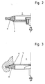
- FIGS. 2 and 3 show two alternative designs of end walls 5.
- the embodiment according to FIG. 2 is applied to the stop surface 6 with the aid of a tension stamp, and that according to FIG. 3 with the aid of a pressure stamp.
- the stop surface 6 is provided, similar to the embodiment shown in FIG. 1, on the side of the end wall 5 facing away from the working space 1.
- the stop surface 6 is in front of the end wall in the direction of the work area 1.
- the aids for blocking the mobility are actuated mechanically or electromechanically in both cases.
Landscapes
- Engineering & Computer Science (AREA)
- General Engineering & Computer Science (AREA)
- Mechanical Engineering (AREA)
- Combined Devices Of Dampers And Springs (AREA)
- Support Of The Bearing (AREA)
- Springs (AREA)
- Arrangement Or Mounting Of Propulsion Units For Vehicles (AREA)
- Fluid-Damping Devices (AREA)
Priority Applications (1)
| Application Number | Priority Date | Filing Date | Title |
|---|---|---|---|
| AT90103873T ATE93937T1 (de) | 1989-08-12 | 1990-02-28 | Gummilager mit hydraulischer daempfung. |
Applications Claiming Priority (2)
| Application Number | Priority Date | Filing Date | Title |
|---|---|---|---|
| DE3926696 | 1989-08-12 | ||
| DE3926696A DE3926696C3 (de) | 1989-08-12 | 1989-08-12 | Gummilager mit hydraulischer Dämpfung |
Publications (2)
| Publication Number | Publication Date |
|---|---|
| EP0413083A1 true EP0413083A1 (fr) | 1991-02-20 |
| EP0413083B1 EP0413083B1 (fr) | 1993-09-01 |
Family
ID=6387016
Family Applications (1)
| Application Number | Title | Priority Date | Filing Date |
|---|---|---|---|
| EP90103873A Expired - Lifetime EP0413083B1 (fr) | 1989-08-12 | 1990-02-28 | Support de caoutchouc avec amortissement hydraulique |
Country Status (10)
| Country | Link |
|---|---|
| US (1) | US5092566A (fr) |
| EP (1) | EP0413083B1 (fr) |
| JP (1) | JP2564691B2 (fr) |
| AT (1) | ATE93937T1 (fr) |
| BR (1) | BR9003812A (fr) |
| CA (1) | CA2021992C (fr) |
| DE (2) | DE3926696C3 (fr) |
| DK (1) | DK0413083T3 (fr) |
| ES (1) | ES2043143T3 (fr) |
| MX (1) | MX172724B (fr) |
Cited By (4)
| Publication number | Priority date | Publication date | Assignee | Title |
|---|---|---|---|---|
| EP0598188A1 (fr) * | 1992-11-17 | 1994-05-25 | BOGE GmbH | Support moteur à amortissement hydraulique |
| EP0622562A1 (fr) * | 1993-04-28 | 1994-11-02 | Honda Giken Kogyo Kabushiki Kaisha | Dispositif de montage pour isolation de vibrations |
| EP0724091A1 (fr) * | 1995-01-25 | 1996-07-31 | Metzeler Gimetall AG | Support de moteur de rigidité réglable |
| CN109823132A (zh) * | 2017-11-23 | 2019-05-31 | 住友理工株式会社 | 橡胶座 |
Families Citing this family (20)
| Publication number | Priority date | Publication date | Assignee | Title |
|---|---|---|---|---|
| JP2843088B2 (ja) * | 1990-02-02 | 1999-01-06 | 東海ゴム工業株式会社 | 流体封入式マウント装置 |
| JPH04302728A (ja) * | 1991-03-29 | 1992-10-26 | Toyoda Gosei Co Ltd | 液封入防振装置 |
| DE4141332C2 (de) * | 1991-12-14 | 1995-05-24 | Freudenberg Carl Fa | Umschaltbares Lager |
| DE69516459T2 (de) * | 1994-07-01 | 2000-09-21 | Bridgestone Corp., Tokio/Tokyo | Vorrichtung zur Schwingungsisolierung |
| JP3407465B2 (ja) * | 1995-03-31 | 2003-05-19 | 株式会社豊田中央研究所 | 液体封入式防振装置 |
| DE19719352B4 (de) * | 1996-05-09 | 2004-03-18 | Denso Corp., Kariya | Elektronisch geregelte Motoraufhängung |
| JP3510962B2 (ja) * | 1997-03-26 | 2004-03-29 | 東洋ゴム工業株式会社 | 液体封入式防振装置 |
| JP3123492B2 (ja) * | 1997-11-20 | 2001-01-09 | 豊田合成株式会社 | 液体封入式防振装置 |
| DE19754753A1 (de) * | 1997-12-10 | 1999-06-17 | Bayerische Motoren Werke Ag | Schaltbares Lager |
| JP2002174288A (ja) | 2000-12-05 | 2002-06-21 | Tokai Rubber Ind Ltd | 空気圧式能動型防振装置 |
| US6708793B2 (en) * | 2001-05-11 | 2004-03-23 | General Motors Corporation | Double-isolated, symmetric, high-damped mount system |
| JP2003074619A (ja) * | 2001-09-05 | 2003-03-12 | Tokai Rubber Ind Ltd | 能動型流体封入式防振装置 |
| CN100340421C (zh) * | 2002-10-22 | 2007-10-03 | 日产自动车株式会社 | 内燃机的减振固定件 |
| DE60330217D1 (de) * | 2002-10-22 | 2010-01-07 | Nissan Motor | Schwingungsdämpfendes Motorlager für Brennkraftmaschine |
| DE10316283A1 (de) * | 2003-04-09 | 2004-10-28 | Trelleborg Automotive Technical Centre Gmbh | Schaltbares Topflager |
| DE10325720B4 (de) * | 2003-06-06 | 2005-09-01 | Zf Boge Elastmetall Gmbh | Hydraulisch dämpfendes Motorlager |
| DE102004011896B8 (de) * | 2004-03-11 | 2010-04-22 | Isoloc Schwingungstechnik Gmbh | Schwingungsisolator |
| DE102004015036B4 (de) * | 2004-03-26 | 2006-01-26 | Audi Ag | Hydraulisch gedämpftes Aggregatelager für Kraftfahrzeuge |
| EP2710278A1 (fr) * | 2011-05-18 | 2014-03-26 | HYDAC Electronic GmbH | Support à amortissement hydraulique pour une unité |
| CN113447187B (zh) * | 2021-06-30 | 2022-10-04 | 重庆工商大学 | 盾构隧道管片振动与冲击预估控制方法以及控制系统 |
Citations (3)
| Publication number | Priority date | Publication date | Assignee | Title |
|---|---|---|---|---|
| DE3210731A1 (de) * | 1982-03-24 | 1983-10-06 | Continental Gummi Werke Ag | Elastisches lager mit hydraulischer daempfung |
| US4712777A (en) * | 1986-08-25 | 1987-12-15 | Lord Corporation | Fluid filled vibration isolator having precisely adjustable dynamic operating characteristics |
| DE3801108A1 (de) * | 1988-01-16 | 1989-07-27 | Audi Ag | Hydraulisches motorlager |
Family Cites Families (12)
| Publication number | Priority date | Publication date | Assignee | Title |
|---|---|---|---|---|
| DE2906282C2 (de) * | 1979-02-19 | 1982-12-09 | Boge Gmbh, 5208 Eitorf | Hydraulisch dämpfendes Einkammerlager |
| DE3436534A1 (de) * | 1984-03-01 | 1986-04-10 | Continental Gummi-Werke Ag, 3000 Hannover | Hydraulisch gedaempftes elastisches lager insbesondere fuer den antriebsmotor in kraftfahrzeugen |
| DE3417927A1 (de) * | 1984-05-15 | 1985-11-21 | Continental Gummi-Werke Ag, 3000 Hannover | Elastisches lager fuer motoren, maschinenaggregate u.dgl. |
| DE3447950A1 (de) * | 1984-06-07 | 1985-12-12 | Audi AG, 8070 Ingolstadt | Hydraulisches motorlager |
| DE3421137A1 (de) * | 1984-06-07 | 1985-12-12 | Audi AG, 8070 Ingolstadt | Lager, insbesondere zur lagerung einer brennkraftmaschine in einem kraftfahrzeug |
| DE3441592A1 (de) * | 1984-11-14 | 1986-05-15 | Continental Gummi-Werke Ag, 3000 Hannover | Hydraulisch gedaempftes elastisches lager |
| JPS62215141A (ja) * | 1986-03-14 | 1987-09-21 | Bridgestone Corp | 防振装置 |
| DE3614162A1 (de) * | 1986-04-26 | 1987-11-05 | Lemfoerder Metallwaren Ag | Zweikammerstuetzlager mit hydraulischer daempfung, insbesonder motorlager in kraftfahrzeugen |
| DE3643556A1 (de) * | 1986-12-19 | 1988-08-18 | Metzeler Gmbh | Hydraulisch daempfendes motorlager |
| US4789142A (en) * | 1987-05-15 | 1988-12-06 | General Motors Corporation | Electronic motor mount with magnetic decoupler |
| DE3805763A1 (de) * | 1988-02-24 | 1989-09-07 | Daimler Benz Ag | Hydraulisch daempfendes gummilager |
| US4901986A (en) * | 1988-03-07 | 1990-02-20 | General Motors Corporation | Air bladder controlled hydraulic engine mount |
-
1989
- 1989-08-12 DE DE3926696A patent/DE3926696C3/de not_active Expired - Lifetime
-
1990
- 1990-02-28 ES ES90103873T patent/ES2043143T3/es not_active Expired - Lifetime
- 1990-02-28 AT AT90103873T patent/ATE93937T1/de not_active IP Right Cessation
- 1990-02-28 DE DE90103873T patent/DE59002542D1/de not_active Expired - Lifetime
- 1990-02-28 DK DK90103873.7T patent/DK0413083T3/da active
- 1990-02-28 EP EP90103873A patent/EP0413083B1/fr not_active Expired - Lifetime
- 1990-03-26 MX MX020045A patent/MX172724B/es unknown
- 1990-07-04 JP JP2177197A patent/JP2564691B2/ja not_active Expired - Lifetime
- 1990-07-26 CA CA002021992A patent/CA2021992C/fr not_active Expired - Fee Related
- 1990-08-03 BR BR909003812A patent/BR9003812A/pt not_active IP Right Cessation
- 1990-08-10 US US07/565,632 patent/US5092566A/en not_active Expired - Fee Related
Patent Citations (3)
| Publication number | Priority date | Publication date | Assignee | Title |
|---|---|---|---|---|
| DE3210731A1 (de) * | 1982-03-24 | 1983-10-06 | Continental Gummi Werke Ag | Elastisches lager mit hydraulischer daempfung |
| US4712777A (en) * | 1986-08-25 | 1987-12-15 | Lord Corporation | Fluid filled vibration isolator having precisely adjustable dynamic operating characteristics |
| DE3801108A1 (de) * | 1988-01-16 | 1989-07-27 | Audi Ag | Hydraulisches motorlager |
Non-Patent Citations (1)
| Title |
|---|
| PATENT ABSTRACTS OF JAPAN vol. 6, no. 163 (M-152)(1041) 26 August 1982, & JP-A-57 77223 (AISHIN SEIKI KK) 14 Mai 1982, * |
Cited By (6)
| Publication number | Priority date | Publication date | Assignee | Title |
|---|---|---|---|---|
| EP0598188A1 (fr) * | 1992-11-17 | 1994-05-25 | BOGE GmbH | Support moteur à amortissement hydraulique |
| EP0622562A1 (fr) * | 1993-04-28 | 1994-11-02 | Honda Giken Kogyo Kabushiki Kaisha | Dispositif de montage pour isolation de vibrations |
| US5779231A (en) * | 1993-04-28 | 1998-07-14 | Honda Giken Kogyo Kabushiki Kaisha | Vibration-isolating mount device |
| EP0724091A1 (fr) * | 1995-01-25 | 1996-07-31 | Metzeler Gimetall AG | Support de moteur de rigidité réglable |
| CN109823132A (zh) * | 2017-11-23 | 2019-05-31 | 住友理工株式会社 | 橡胶座 |
| CN109823132B (zh) * | 2017-11-23 | 2022-04-29 | 住友理工株式会社 | 橡胶座 |
Also Published As
| Publication number | Publication date |
|---|---|
| JPH0384238A (ja) | 1991-04-09 |
| DE3926696C3 (de) | 1998-02-26 |
| ATE93937T1 (de) | 1993-09-15 |
| DK0413083T3 (da) | 1993-11-01 |
| ES2043143T3 (es) | 1993-12-16 |
| JP2564691B2 (ja) | 1996-12-18 |
| MX172724B (es) | 1994-01-10 |
| DE3926696C2 (fr) | 1991-06-20 |
| DE59002542D1 (de) | 1993-10-07 |
| CA2021992C (fr) | 1994-10-04 |
| CA2021992A1 (fr) | 1991-02-13 |
| EP0413083B1 (fr) | 1993-09-01 |
| US5092566A (en) | 1992-03-03 |
| DE3926696A1 (de) | 1991-02-14 |
| BR9003812A (pt) | 1991-09-03 |
Similar Documents
| Publication | Publication Date | Title |
|---|---|---|
| EP0413083B1 (fr) | Support de caoutchouc avec amortissement hydraulique | |
| EP0262296B1 (fr) | Support en caoutchouc à amortissement hydraulique | |
| EP0643238B1 (fr) | Support d'amortissement hydraulique commutable | |
| DE60013391T2 (de) | Hydraulisches, schwingungsdämpfendes Lager und dieses enthaltendes, aktives Schwingungsdämpfungssystem | |
| EP0547287B1 (fr) | Support commutable | |
| DE10134017A1 (de) | Mit einem Fluid gefüllte Schwingungsdämpfungsvorrichtung mit einer Druckaufnahmekammer, deren Federsteifigkeit steuerbar ist | |
| DE10045701C2 (de) | Fluidgefüllter aktiver elastischer Träger, bei dem ein Schwingelement durch zwei elastische Stützelemente elastisch gestützt ist | |
| DE102017007999B4 (de) | Schaltbares Hydrolager | |
| DE69824135T2 (de) | Schwingungsdämpfende Vorrichtung mit Flüssigkeitskammern auf gegenüberliegenden Seiten einer Partitionsstruktur mit bewegbarer Gummiplatte | |
| DE3246587A1 (de) | Hydraulisch daempfendes gummilager | |
| DE10019872A1 (de) | Fluidgefüllte Aktivschwingungsdämpfungsvorrichtung mit Stabilisierungselement zum Stabilisieren eines Schwingungselementes | |
| DE69714001T2 (de) | Flüssigkeitsgefüllte schwingungsdämpfende Vorrichtung mit Teil, das eine mitwirkende Flüssigkeitskammer teilweise begrenzt und pneumatisch oszilliert wird | |
| DE4212190C2 (de) | Elastische Lagerung mit einer Fluidfüllung | |
| EP0527302B1 (fr) | Support en caoutchouc à amortissement hydraulique | |
| DE3920153C2 (fr) | ||
| WO2008086777A1 (fr) | Dispositif pour supprimer les résonances propres dans un parcours hydraulique | |
| DE19915798A1 (de) | Schaltbares, hydraulisch dämpfendes Lager | |
| EP1055839B1 (fr) | Support amorti hydrauliquement | |
| DE19958011A1 (de) | Elastisches Lager mit hydraulischer Dämpfung | |
| EP0528253B1 (fr) | Palier de support à amortissement hydraulique pour parties de châssis de voiture | |
| DE19812837C2 (de) | Hydraulisch dämpfendes Motorlager | |
| DE102004060499B4 (de) | Aggregatelager | |
| DE10121399A1 (de) | Hydraulisch gedämpftes Aggregatlager | |
| EP0527295B1 (fr) | Support en caoutchouc à amortissement hydraulique | |
| EP0848183B1 (fr) | Support hydraulique à chambres multiples |
Legal Events
| Date | Code | Title | Description |
|---|---|---|---|
| PUAI | Public reference made under article 153(3) epc to a published international application that has entered the european phase |
Free format text: ORIGINAL CODE: 0009012 |
|
| AK | Designated contracting states |
Kind code of ref document: A1 Designated state(s): AT BE CH DE DK ES FR GB GR IT LI LU NL SE |
|
| 17P | Request for examination filed |
Effective date: 19910131 |
|
| 17Q | First examination report despatched |
Effective date: 19911216 |
|
| ITF | It: translation for a ep patent filed | ||
| GRAA | (expected) grant |
Free format text: ORIGINAL CODE: 0009210 |
|
| AK | Designated contracting states |
Kind code of ref document: B1 Designated state(s): AT BE CH DE DK ES FR GB GR IT LI LU NL SE |
|
| REF | Corresponds to: |
Ref document number: 93937 Country of ref document: AT Date of ref document: 19930915 Kind code of ref document: T |
|
| ET | Fr: translation filed | ||
| REF | Corresponds to: |
Ref document number: 59002542 Country of ref document: DE Date of ref document: 19931007 |
|
| GBT | Gb: translation of ep patent filed (gb section 77(6)(a)/1977) |
Effective date: 19930920 |
|
| REG | Reference to a national code |
Ref country code: DK Ref legal event code: T3 |
|
| REG | Reference to a national code |
Ref country code: ES Ref legal event code: FG2A Ref document number: 2043143 Country of ref document: ES Kind code of ref document: T3 |
|
| EPTA | Lu: last paid annual fee | ||
| PLBE | No opposition filed within time limit |
Free format text: ORIGINAL CODE: 0009261 |
|
| STAA | Information on the status of an ep patent application or granted ep patent |
Free format text: STATUS: NO OPPOSITION FILED WITHIN TIME LIMIT |
|
| RAP4 | Party data changed (patent owner data changed or rights of a patent transferred) |
Owner name: FIRMA CARL FREUDENBERG |
|
| 26N | No opposition filed | ||
| EAL | Se: european patent in force in sweden |
Ref document number: 90103873.7 |
|
| ITTA | It: last paid annual fee | ||
| PGFP | Annual fee paid to national office [announced via postgrant information from national office to epo] |
Ref country code: CH Payment date: 19960123 Year of fee payment: 7 |
|
| PGFP | Annual fee paid to national office [announced via postgrant information from national office to epo] |
Ref country code: SE Payment date: 19960129 Year of fee payment: 7 |
|
| PGFP | Annual fee paid to national office [announced via postgrant information from national office to epo] |
Ref country code: LU Payment date: 19960201 Year of fee payment: 7 |
|
| PGFP | Annual fee paid to national office [announced via postgrant information from national office to epo] |
Ref country code: AT Payment date: 19960209 Year of fee payment: 7 |
|
| PGFP | Annual fee paid to national office [announced via postgrant information from national office to epo] |
Ref country code: DK Payment date: 19960227 Year of fee payment: 7 |
|
| PGFP | Annual fee paid to national office [announced via postgrant information from national office to epo] |
Ref country code: NL Payment date: 19960229 Year of fee payment: 7 Ref country code: BE Payment date: 19960229 Year of fee payment: 7 |
|
| PG25 | Lapsed in a contracting state [announced via postgrant information from national office to epo] |
Ref country code: LU Free format text: LAPSE BECAUSE OF NON-PAYMENT OF DUE FEES Effective date: 19970228 Ref country code: LI Effective date: 19970228 Ref country code: DK Effective date: 19970228 Ref country code: CH Effective date: 19970228 Ref country code: BE Effective date: 19970228 Ref country code: AT Effective date: 19970228 |
|
| REG | Reference to a national code |
Ref country code: DK Ref legal event code: EBP |
|
| PG25 | Lapsed in a contracting state [announced via postgrant information from national office to epo] |
Ref country code: SE Effective date: 19970301 |
|
| BERE | Be: lapsed |
Owner name: FIRMA CARL FREUDENBERG Effective date: 19970228 |
|
| PG25 | Lapsed in a contracting state [announced via postgrant information from national office to epo] |
Ref country code: NL Effective date: 19970901 |
|
| REG | Reference to a national code |
Ref country code: CH Ref legal event code: PL |
|
| NLV4 | Nl: lapsed or anulled due to non-payment of the annual fee |
Effective date: 19970901 |
|
| EUG | Se: european patent has lapsed |
Ref document number: 90103873.7 |
|
| PGFP | Annual fee paid to national office [announced via postgrant information from national office to epo] |
Ref country code: GB Payment date: 19980121 Year of fee payment: 9 |
|
| PGFP | Annual fee paid to national office [announced via postgrant information from national office to epo] |
Ref country code: GR Payment date: 19980129 Year of fee payment: 9 |
|
| PGFP | Annual fee paid to national office [announced via postgrant information from national office to epo] |
Ref country code: DE Payment date: 19980203 Year of fee payment: 9 |
|
| PGFP | Annual fee paid to national office [announced via postgrant information from national office to epo] |
Ref country code: FR Payment date: 19980213 Year of fee payment: 9 |
|
| PGFP | Annual fee paid to national office [announced via postgrant information from national office to epo] |
Ref country code: ES Payment date: 19980219 Year of fee payment: 9 |
|
| PG25 | Lapsed in a contracting state [announced via postgrant information from national office to epo] |
Ref country code: DE Free format text: LAPSE BECAUSE OF THE APPLICANT RENOUNCES Effective date: 19980820 |
|
| PG25 | Lapsed in a contracting state [announced via postgrant information from national office to epo] |
Ref country code: GR Free format text: LAPSE BECAUSE OF NON-PAYMENT OF DUE FEES Effective date: 19990228 Ref country code: GB Free format text: LAPSE BECAUSE OF NON-PAYMENT OF DUE FEES Effective date: 19990228 |
|
| PG25 | Lapsed in a contracting state [announced via postgrant information from national office to epo] |
Ref country code: ES Free format text: LAPSE BECAUSE OF NON-PAYMENT OF DUE FEES Effective date: 19990301 |
|
| GBPC | Gb: european patent ceased through non-payment of renewal fee |
Effective date: 19990228 |
|
| PG25 | Lapsed in a contracting state [announced via postgrant information from national office to epo] |
Ref country code: FR Free format text: LAPSE BECAUSE OF NON-PAYMENT OF DUE FEES Effective date: 19991029 |
|
| REG | Reference to a national code |
Ref country code: FR Ref legal event code: ST |
|
| REG | Reference to a national code |
Ref country code: ES Ref legal event code: FD2A Effective date: 20010910 |
|
| PG25 | Lapsed in a contracting state [announced via postgrant information from national office to epo] |
Ref country code: IT Free format text: LAPSE BECAUSE OF NON-PAYMENT OF DUE FEES Effective date: 20050228 |