EP0413093B1 - Machine à laver avec dispositif de fixation du moteur d'entraînement - Google Patents
Machine à laver avec dispositif de fixation du moteur d'entraînement Download PDFInfo
- Publication number
- EP0413093B1 EP0413093B1 EP90109332A EP90109332A EP0413093B1 EP 0413093 B1 EP0413093 B1 EP 0413093B1 EP 90109332 A EP90109332 A EP 90109332A EP 90109332 A EP90109332 A EP 90109332A EP 0413093 B1 EP0413093 B1 EP 0413093B1
- Authority
- EP
- European Patent Office
- Prior art keywords
- arm
- motor
- washing machine
- carrier frame
- pivot
- Prior art date
- Legal status (The legal status is an assumption and is not a legal conclusion. Google has not performed a legal analysis and makes no representation as to the accuracy of the status listed.)
- Expired - Lifetime
Links
Images
Classifications
-
- D—TEXTILES; PAPER
- D06—TREATMENT OF TEXTILES OR THE LIKE; LAUNDERING; FLEXIBLE MATERIALS NOT OTHERWISE PROVIDED FOR
- D06F—LAUNDERING, DRYING, IRONING, PRESSING OR FOLDING TEXTILE ARTICLES
- D06F37/00—Details specific to washing machines covered by groups D06F21/00 - D06F25/00
-
- D—TEXTILES; PAPER
- D06—TREATMENT OF TEXTILES OR THE LIKE; LAUNDERING; FLEXIBLE MATERIALS NOT OTHERWISE PROVIDED FOR
- D06F—LAUNDERING, DRYING, IRONING, PRESSING OR FOLDING TEXTILE ARTICLES
- D06F37/00—Details specific to washing machines covered by groups D06F21/00 - D06F25/00
- D06F37/20—Mountings, e.g. resilient mountings, for the rotary receptacle, motor, tub or casing; Preventing or damping vibrations
- D06F37/206—Mounting of motor
Definitions
- the invention relates to a drum washing machine with a washing drum rotatably mounted about a horizontal axis in a star-shaped support frame, which can be driven via a gear by a motor attached to an arm of the support frame, which is connected to a swing arm connected to the drive-side motor bearing plate Swinging bearing eye of the support frame arm is mounted so that it can oscillate within limits and is fastened to the support frame arm in a curved elongated hole by means of a screw fastening on the drive-side motor end shield.
- Such a drum washing machine is known from DE-OS 31 32 211.
- this solution has advantages in terms of the transmission and propagation of noises which the drive motor necessarily causes.
- this solution is more efficient compared to other types of fastening with several auxiliary components.
- this fastening solution places high demands on the screws to be used for fastening the drive motor. Since the motor belongs to the vibrating unit of a drum washing machine and has a relatively high mass, the alternating acceleration forces put a considerable strain on the screw heads. Equally high loads also occur during transport impacts that act in the direction of the drum axis of the washing machine. Shocks acting transversely to the drum axis load the screws.
- the invention has for its object to design the mounting area in the known drum washing machine so that the aforementioned loads do not affect the screw heads, but the cast parts (support arm and motor end shield).
- this object is achieved in that the motor end shield engages with its screw fastening from one side of the support frame arm and the swing arm from the other side.
- the oscillating bearing consists of a bush inserted into the bearing eye and a pin attached to the oscillating arm, a particular simplification of assembly results from the fact that the motor with its oscillating arm pin can be hooked into the oscillating bearing and not during further assembly must be held more.
- the bearing journal consists of a screw which penetrates the swing arm and the support arm. Together with a nut screwed onto the inserted threaded pin, it can ensure the secure mounting of the motor.This is particularly important if, for any reason, the fastening of the drive motor cannot be done by a single screw alone - namely the screw mounting on the motor end shield can be.
- the support frame arm has a guide finger below its elongated hole, which supports the drive-side motor end shield in the mounted position of the motor, far from the screw fastening .
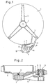
- the tub 1 of a washing machine is usually fastened in a star-shaped support frame 2, in the hub 3 of which the bearing journal of a laundry drum is rotatably mounted in a manner not shown here.
- a foot-like extension 5 is attached to one of the downward-pointing arms of the support frame 2, namely on the arm 4, which extends beyond the outer contour of the tub 1.
- the foot-like extension 5 has two fastening points, a pivot bearing eye 6 and an arcuate elongated hole 7.
- the pivot of a pivot arm 8 is suspended in the pivot bearing eye 6 and is a fixed component of the drive-side end plate 9 of the drive motor 10.
- the motor 10 can be pivoted about the pivot bearing eye 6, so that a belt (not shown) which wraps around the drive pinion 12 of the motor 10 can be tensioned.
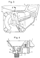
- the motor end shield 9 rests in the region of the end of the foot-like extension 5 carrying the slot 7 from behind on the support frame arm 4, while the swing arm 8 of the end shield 9 grips around the foot-like extension 5 and from the front side of the Support frame arms 4 attacks.
- the motor end shield 9 forms, with its swing arm 8, a clasp, as it were, around the foot-like extension 5.
- the swing arm 8 is integrally connected to a bearing pin 13 which is directed forward from the rear of the tub and engages in the bearing eye 6.
- the bearing eye 6 is also reinforced with a rubber-metal bushing 14, the inner metal bushing of which has a sliding fit with the pin 13.
- the swing arm 8 can have an inserted screw with a threadless sliding shaft at this point, which can be secured from the front side of the support arm 4 with a nut.
- a screw is also provided for fastening the end of the foot-like extension 5 carrying the elongated hole 7 in the screw thread 11 of the motor end shield 9.
- the end of the foot-like extension 5 containing the elongated hole 7 also carries a guide finger 15.
- This guide finger 15 extends up to the annular area of the end shield through which the motor shaft 16 with its pinion 12 attached to the front extends outwards protrudes.
- the distance of the ring surface of the end shield 9 which wraps around the motor shaft 16 to the front surface 18 of the guide finger 15 is intended to clarify that this ring surface should lie as closely as possible to the front surface 18 of the guide finger 15, but in no case a greater distance from the front contact surface of the Stubs for the thread 11 may have, as the distance between the surfaces 17 and 18 on the foot-shaped extension 5.
- both the foot-like extension 5 and the swing arm 8 are cranked so that the contact surfaces on the swing bearing eye and on the screw fastening are changed.
- this spatial arrangement can also be achieved in that either only the foot-like extension 5 or only the swing arm 8 is cranked accordingly.
- the guide finger 15 can also have a different shape and / or engage at a different location on the motor end shield 9.
- the shape of the motor mounting according to the invention prevents excessive loads on the screw heads in the event of impacts on the vibrating unit. Shocks from the front are partially absorbed by the pin attachment of the swing arm 8, while shocks from behind on the vibrating unit are absorbed by the contact surfaces between the motor end shield 9 and the foot-like extension 5.
- the rubber-metal bushing shown in FIG. 2 dampens transmissions of vibrations generated by the drive motor 10 to the unit. An additional simplification of the assembly is given by the swing arm pivot designed according to FIG. 2, because only one screw has to be tightened for fastening the motor.
Landscapes
- Engineering & Computer Science (AREA)
- Textile Engineering (AREA)
- Connection Of Motors, Electrical Generators, Mechanical Devices, And The Like (AREA)
- Motor Or Generator Frames (AREA)
- Sewing Machines And Sewing (AREA)
- Main Body Construction Of Washing Machines And Laundry Dryers (AREA)
- Treatment Of Fiber Materials (AREA)
- Accessory Of Washing/Drying Machine, Commercial Washing/Drying Machine, Other Washing/Drying Machine (AREA)
- Detail Structures Of Washing Machines And Dryers (AREA)
Claims (7)
- Lave-linge à tambour comportant un tambour à linge qui est monté tournant autour d'un axe horizontal dans un bâti (2) en forme d'étoile et, par l'intermédiaire d'un réducteur, est entraîné par un moteur (10) fixé sur une patte (4, 5) du bâti, lequel moteur, par l'intermédiaire d'un bras oscillant (8) lié au flasque de palier (9) du moteur côté entraînement, est monté avec possibilité d'oscillation limitée sur un bossage (6) formant palier oscillant de la patte du bâti et est fixé dans un trou oblong (7) de la patte du bâti par l'intermédiaire d'une fixation à vis (7, 11) sur le flasque (9) de palier du moteur côté entraînement, caractérisé par le fait que le flasque de palier (9) du moteur est monté par une fixation à vis (7, 11) d'un côté (17) de la patte (4, 5) du bâti tandis que le bras oscillant (8) est monté de l'autre côté.
- Lave-linge à tambour selon la revendication 1, caractérisé par le fait que la zone de fixation (15) de la patte (4, 5) du bâti est coudée entre le bossage (6) et le trou oblong (7).
- Lave-linge à tambour selon la revendication 1 ou 2, caractérisé par le fait que le bras oscillant (8) est coudé entre le moyen de fixation par vis (7, 11) et le palier (6, 13).
- Lave-linge à tambour selon l'une des revendications 1 à 3, caractérisé par le fait que le palier oscillant (6, 13) est formé par une douille (14) montée dans le bossage de palier (6) et un tourillon (13) prévu sur le bras oscillant (8).
- Lave-linge à tambour selon la revendication 4, caractérisé par le fait que le tourillon (13) fait partie intégrante du bras oscillant (8).
- Lave-linge à tambour selon la revendication 1 à 4, caractérisé par le fait que le tourillon (13) est constitué par une vis qui traverse le bras oscillant (8) et la patte (4, 5) du bâti.
- Lave-linge à tambour selon l'une des revendications précédentes, caractérisé par le fait que la patte (4, 5) du bâti présente, sous son trou oblong (7), un doigt de guidage (15) qui, en position de montage du moteur (10) soutient le flasque de palier (9) du moteur en un point éloigné de la fixation par vis (7, 11).
Priority Applications (1)
| Application Number | Priority Date | Filing Date | Title |
|---|---|---|---|
| AT9090109332T ATE104707T1 (de) | 1989-08-17 | 1990-05-17 | Trommelwaschmaschine mit einer befestigungsvorrichtung des antriebsmotors. |
Applications Claiming Priority (2)
| Application Number | Priority Date | Filing Date | Title |
|---|---|---|---|
| DE3927166 | 1989-08-17 | ||
| DE3927166A DE3927166A1 (de) | 1989-08-17 | 1989-08-17 | Trommelwaschmaschine |
Publications (2)
| Publication Number | Publication Date |
|---|---|
| EP0413093A1 EP0413093A1 (fr) | 1991-02-20 |
| EP0413093B1 true EP0413093B1 (fr) | 1994-04-20 |
Family
ID=6387295
Family Applications (1)
| Application Number | Title | Priority Date | Filing Date |
|---|---|---|---|
| EP90109332A Expired - Lifetime EP0413093B1 (fr) | 1989-08-17 | 1990-05-17 | Machine à laver avec dispositif de fixation du moteur d'entraînement |
Country Status (8)
| Country | Link |
|---|---|
| EP (1) | EP0413093B1 (fr) |
| KR (1) | KR910004884A (fr) |
| AT (1) | ATE104707T1 (fr) |
| DD (1) | DD297199A5 (fr) |
| DE (2) | DE3927166A1 (fr) |
| ES (1) | ES2051408T3 (fr) |
| HK (1) | HK91595A (fr) |
| TR (1) | TR24552A (fr) |
Families Citing this family (13)
| Publication number | Priority date | Publication date | Assignee | Title |
|---|---|---|---|---|
| DE4119516A1 (de) * | 1990-06-15 | 1992-01-02 | Miele & Cie | Trommelwaschmaschine |
| DE4109164C2 (de) * | 1991-03-20 | 1995-09-28 | Bosch Siemens Hausgeraete | Von vorn beschickbare Waschmaschine |
| EP0750064A1 (fr) | 1995-06-24 | 1996-12-27 | Whirlpool Europe B.V. | Méthode de fixation pour le moteur dans une machine à laver domestique et la machine en résultant |
| ES2154536B1 (es) * | 1998-02-19 | 2001-11-01 | Balay Sa | Sistema de sujecion del motor a la cuba de lavadoras. |
| ES2162530B1 (es) * | 1998-05-22 | 2002-08-01 | Balay Sa | Sistema de sujecion del motor de lavadoras a la cuba. |
| DE102004047996A1 (de) * | 2004-10-01 | 2006-04-06 | BSH Bosch und Siemens Hausgeräte GmbH | Tragstern für eine Waschmaschine |
| ITPN20070069A1 (it) * | 2007-09-27 | 2009-03-28 | Appliances Components Companie | "macchina lavabiancheria a cesto rotante o elettrodomestico simile con un sistema di fissaggio di un motore elettrico" |
| ES2378937A1 (es) * | 2009-10-01 | 2012-04-19 | Bsh Electrodomésticos España, S.A. | M�?quina lavadora. |
| EP2388365A1 (fr) * | 2010-05-19 | 2011-11-23 | Miele & Cie. KG | Lave-linge à tambour |
| ES2430948B1 (es) * | 2012-05-22 | 2014-09-10 | Bsh Electrodomésticos España, S.A. | Aparato electrodoméstico con sistema de fijación de motor |
| DE102016108805A1 (de) * | 2016-05-12 | 2017-11-16 | Miele & Cie. Kg | Aggregat für einen Waschautomaten und Waschautomat |
| CN106968082B (zh) * | 2017-03-29 | 2019-09-17 | 无锡小天鹅电器有限公司 | 用于滚筒洗衣机的三脚架及具有其的滚筒洗衣机 |
| KR102776910B1 (ko) * | 2021-04-21 | 2025-03-10 | 엘지전자 주식회사 | 의류처리장치 |
Family Cites Families (2)
| Publication number | Priority date | Publication date | Assignee | Title |
|---|---|---|---|---|
| GB956670A (en) * | 1962-04-21 | 1964-04-29 | Constructa Werke Gmbh | Improvements relating to washing and spin-drying machines |
| DE3132211A1 (de) * | 1981-08-14 | 1983-03-03 | Licentia Patent-Verwaltungs-Gmbh, 6000 Frankfurt | "trommelwaschmaschine" |
-
1989
- 1989-08-17 DE DE3927166A patent/DE3927166A1/de not_active Withdrawn
-
1990
- 1990-05-17 DE DE59005417T patent/DE59005417D1/de not_active Expired - Fee Related
- 1990-05-17 ES ES90109332T patent/ES2051408T3/es not_active Expired - Lifetime
- 1990-05-17 AT AT9090109332T patent/ATE104707T1/de not_active IP Right Cessation
- 1990-05-17 EP EP90109332A patent/EP0413093B1/fr not_active Expired - Lifetime
- 1990-08-07 KR KR1019900012086A patent/KR910004884A/ko not_active Ceased
- 1990-08-15 DD DD90343467A patent/DD297199A5/de not_active IP Right Cessation
- 1990-08-31 TR TR90/0750A patent/TR24552A/xx unknown
-
1995
- 1995-06-08 HK HK91595A patent/HK91595A/xx not_active IP Right Cessation
Also Published As
| Publication number | Publication date |
|---|---|
| ATE104707T1 (de) | 1994-05-15 |
| DD297199A5 (de) | 1992-01-02 |
| DE59005417D1 (de) | 1994-05-26 |
| HK91595A (en) | 1995-06-16 |
| ES2051408T3 (es) | 1994-06-16 |
| KR910004884A (ko) | 1991-03-29 |
| DE3927166A1 (de) | 1991-02-21 |
| EP0413093A1 (fr) | 1991-02-20 |
| TR24552A (tr) | 1991-11-01 |
Similar Documents
| Publication | Publication Date | Title |
|---|---|---|
| EP0413093B1 (fr) | Machine à laver avec dispositif de fixation du moteur d'entraînement | |
| DE102008058426B4 (de) | Zubehörmontageaufbau | |
| DE60133080T2 (de) | Wischeranlage für Fahrzeuge | |
| DE60311728T2 (de) | Motorträger | |
| DE69304730T2 (de) | Küchenmaschine mit elastischer Aufhängung des Rahmens | |
| DE2138294C3 (de) | Schwingungsdämpfende Griffaufhängung | |
| EP1293404B1 (fr) | Bras d'essuie-glace et dispositif d'essuie-glace, en particulier pour un véhicule | |
| DE2529949C3 (de) | Kraftfahrzeug-Scheibenwischer | |
| EP0446560B1 (fr) | Mécanisme de battage avec arbre du battant excentré pour métier à tisser | |
| DE2715463A1 (de) | Vorderradaufhaengung fuer ein kraftfahrzeug | |
| DE3901333C2 (de) | Schwingungsfeste Motorhalterung | |
| DE3234551A1 (de) | Naehmaschine | |
| EP0098635B1 (fr) | Outil pour travailler les produits de récolte se trouvant sur le sol | |
| DE2248016C3 (de) | Trommelwaschmaschine | |
| DE2918984A1 (de) | Vorrichtung zum antrieb einer um ihre laengsachse schwingbar angeordneten welle | |
| WO2008080826A1 (fr) | Unité d'entraînement pour un sèche-linge à usage domestique | |
| DE969859C (de) | Auf Gleiskettenantrieb umstellbares Raederfahrzeug | |
| DE3803643C2 (de) | Sicherheitseinrichtung für den Insassen eines Kraftfahrzeugs | |
| DE4026549C2 (de) | Von vorn beschickbare Waschmaschine | |
| DE3904225A1 (de) | Schlepper, insbesondere fuer landwirtschaftlichen einsatz stichwort: kippbare kabine | |
| DE3147348A1 (de) | Maehmaschine mit antriebsuebertragung | |
| AT153716B (de) | Kettenwirkmaschine. | |
| DE19815606B4 (de) | Halterung für ein Getriebegehäuse | |
| DE2006466C3 (de) | Vibrationshandschleifgerät für Kreis- und Geradschliff | |
| AT257905B (de) | Tragbare Motorkettensäge |
Legal Events
| Date | Code | Title | Description |
|---|---|---|---|
| PUAI | Public reference made under article 153(3) epc to a published international application that has entered the european phase |
Free format text: ORIGINAL CODE: 0009012 |
|
| AK | Designated contracting states |
Kind code of ref document: A1 Designated state(s): AT CH DE ES FR GB GR IT LI SE |
|
| 17P | Request for examination filed |
Effective date: 19910806 |
|
| RAP3 | Party data changed (applicant data changed or rights of an application transferred) |
Owner name: BOSCH-SIEMENS HAUSGERAETE GMBH |
|
| 17Q | First examination report despatched |
Effective date: 19930924 |
|
| GRAA | (expected) grant |
Free format text: ORIGINAL CODE: 0009210 |
|
| AK | Designated contracting states |
Kind code of ref document: B1 Designated state(s): AT CH DE ES FR GB GR IT LI SE |
|
| REF | Corresponds to: |
Ref document number: 104707 Country of ref document: AT Date of ref document: 19940515 Kind code of ref document: T |
|
| GBT | Gb: translation of ep patent filed (gb section 77(6)(a)/1977) |
Effective date: 19940420 |
|
| ET | Fr: translation filed | ||
| REF | Corresponds to: |
Ref document number: 59005417 Country of ref document: DE Date of ref document: 19940526 |
|
| REG | Reference to a national code |
Ref country code: ES Ref legal event code: FG2A Ref document number: 2051408 Country of ref document: ES Kind code of ref document: T3 |
|
| ITF | It: translation for a ep patent filed | ||
| REG | Reference to a national code |
Ref country code: GR Ref legal event code: FG4A Free format text: 3011848 |
|
| EAL | Se: european patent in force in sweden |
Ref document number: 90109332.8 |
|
| PLBE | No opposition filed within time limit |
Free format text: ORIGINAL CODE: 0009261 |
|
| STAA | Information on the status of an ep patent application or granted ep patent |
Free format text: STATUS: NO OPPOSITION FILED WITHIN TIME LIMIT |
|
| 26N | No opposition filed | ||
| PGFP | Annual fee paid to national office [announced via postgrant information from national office to epo] |
Ref country code: GR Payment date: 19950505 Year of fee payment: 6 |
|
| PG25 | Lapsed in a contracting state [announced via postgrant information from national office to epo] |
Ref country code: GR Free format text: THE PATENT HAS BEEN ANNULLED BY A DECISION OF A NATIONAL AUTHORITY Effective date: 19961130 |
|
| REG | Reference to a national code |
Ref country code: GR Ref legal event code: MM2A Free format text: 3011848 |
|
| PGFP | Annual fee paid to national office [announced via postgrant information from national office to epo] |
Ref country code: FR Payment date: 19970410 Year of fee payment: 8 |
|
| PGFP | Annual fee paid to national office [announced via postgrant information from national office to epo] |
Ref country code: SE Payment date: 19970417 Year of fee payment: 8 |
|
| PGFP | Annual fee paid to national office [announced via postgrant information from national office to epo] |
Ref country code: GB Payment date: 19970509 Year of fee payment: 8 |
|
| PGFP | Annual fee paid to national office [announced via postgrant information from national office to epo] |
Ref country code: AT Payment date: 19970513 Year of fee payment: 8 |
|
| PGFP | Annual fee paid to national office [announced via postgrant information from national office to epo] |
Ref country code: ES Payment date: 19970529 Year of fee payment: 8 |
|
| PGFP | Annual fee paid to national office [announced via postgrant information from national office to epo] |
Ref country code: CH Payment date: 19970725 Year of fee payment: 8 |
|
| PG25 | Lapsed in a contracting state [announced via postgrant information from national office to epo] |
Ref country code: GB Free format text: LAPSE BECAUSE OF NON-PAYMENT OF DUE FEES Effective date: 19980517 Ref country code: AT Free format text: LAPSE BECAUSE OF NON-PAYMENT OF DUE FEES Effective date: 19980517 |
|
| PG25 | Lapsed in a contracting state [announced via postgrant information from national office to epo] |
Ref country code: SE Free format text: LAPSE BECAUSE OF NON-PAYMENT OF DUE FEES Effective date: 19980518 Ref country code: ES Free format text: LAPSE BECAUSE OF EXPIRATION OF PROTECTION Effective date: 19980518 |
|
| PG25 | Lapsed in a contracting state [announced via postgrant information from national office to epo] |
Ref country code: LI Free format text: LAPSE BECAUSE OF NON-PAYMENT OF DUE FEES Effective date: 19980531 Ref country code: FR Free format text: LAPSE BECAUSE OF NON-PAYMENT OF DUE FEES Effective date: 19980531 Ref country code: CH Free format text: LAPSE BECAUSE OF NON-PAYMENT OF DUE FEES Effective date: 19980531 |
|
| GBPC | Gb: european patent ceased through non-payment of renewal fee |
Effective date: 19980517 |
|
| REG | Reference to a national code |
Ref country code: CH Ref legal event code: PL |
|
| EUG | Se: european patent has lapsed |
Ref document number: 90109332.8 |
|
| REG | Reference to a national code |
Ref country code: FR Ref legal event code: ST |
|
| REG | Reference to a national code |
Ref country code: ES Ref legal event code: FD2A Effective date: 20000201 |
|
| PGFP | Annual fee paid to national office [announced via postgrant information from national office to epo] |
Ref country code: DE Payment date: 20020620 Year of fee payment: 13 |
|
| PG25 | Lapsed in a contracting state [announced via postgrant information from national office to epo] |
Ref country code: DE Free format text: LAPSE BECAUSE OF NON-PAYMENT OF DUE FEES Effective date: 20031202 |
|
| PG25 | Lapsed in a contracting state [announced via postgrant information from national office to epo] |
Ref country code: IT Free format text: LAPSE BECAUSE OF NON-PAYMENT OF DUE FEES;WARNING: LAPSES OF ITALIAN PATENTS WITH EFFECTIVE DATE BEFORE 2007 MAY HAVE OCCURRED AT ANY TIME BEFORE 2007. THE CORRECT EFFECTIVE DATE MAY BE DIFFERENT FROM THE ONE RECORDED. Effective date: 20050517 |