EP0413202A1 - Feilenheft - Google Patents
Feilenheft Download PDFInfo
- Publication number
- EP0413202A1 EP0413202A1 EP90114806A EP90114806A EP0413202A1 EP 0413202 A1 EP0413202 A1 EP 0413202A1 EP 90114806 A EP90114806 A EP 90114806A EP 90114806 A EP90114806 A EP 90114806A EP 0413202 A1 EP0413202 A1 EP 0413202A1
- Authority
- EP
- European Patent Office
- Prior art keywords
- file
- booklet
- constriction
- cross
- diameter
- Prior art date
- Legal status (The legal status is an assumption and is not a legal conclusion. Google has not performed a legal analysis and makes no representation as to the accuracy of the status listed.)
- Granted
Links
Images
Classifications
-
- B—PERFORMING OPERATIONS; TRANSPORTING
- B25—HAND TOOLS; PORTABLE POWER-DRIVEN TOOLS; MANIPULATORS
- B25G—HANDLES FOR HAND IMPLEMENTS
- B25G1/00—Handle constructions
- B25G1/10—Handle constructions characterised by material or shape
- B25G1/102—Handle constructions characterised by material or shape the shape being specially adapted to facilitate handling or improve grip
Definitions
- the invention relates to a file handle with an elongated shape, which has a rounded end and a front constriction in the file-side end region of the handle.
- Files usually have a handle made of wood or plastic that has an elongated shape. A very flat constriction is present in the file-side end area, while the booklet gradually tapers in the area of the opposite free end, so that a rounded, but relatively narrow end surface is formed.
- the handle usually has a circular cross section.
- the handling of a file must meet different requirements. Files of a certain size are usually handled with both hands, with one hand on the handle. The file must be controlled with your hands, i.e. a certain orientation of the file, usually a processing area of the file, must be specified. The file must be positioned in its angular position with respect to three mutually perpendicular axes. In addition, however, the actual file processing still has to be carried out, in which a force has to be exerted during the movement of the file. This force must be applied once in the direction of movement, usually the feed direction, but also in a direction perpendicular to the machining surface. The file booklets currently used do not meet these different requirements.
- the invention has for its object to provide a file handle that is better adapted to the needs of the user of a file.
- the invention proposes to give the free end of the file handle approximately the shape of at least half a ball, the diameter of which is in a range from approximately 28 to 32 mm.
- the spherical shape creates a shape that lies well in the palm of the hand, which leads to a reduction in the surface load and thus to a better and fatigue-free action of the hand on the file. Because of the spherical shape, pressure can be exerted not only in the longitudinal direction of the file, ie when pushing, but also at an angle to this direction, so that a good filing result can be achieved.
- the free end of the file handle has the shape of more than half a ball. This means that the cross section of the file handle the end is reduced so that the end forms a larger part than a hemisphere. This creates a contact surface for the fingertip of the little and ring finger.
- a cross-sectional constriction is arranged directly in front of the partially spherical end of the booklet. This can also be used to place the little finger. This increases the grip of the booklet. This is particularly important when moving backwards, i.e. when pulling the file, since the file can then be taken along more easily.
- the cross-section of the booklet increases from the end constriction to a point of a local cross-sectional maximum at which the diameter of the booklet is approximately equal to the diameter of the part-spherical end.
- this point of the maximum diameter lies approximately in the middle of the longitudinal extent of the booklet.
- the cross section of the booklet decreases again from the point of the maximum cross section to the front constriction.
- the constriction is used to insert the thumb.
- the invention now proposes to make the constriction known per se much clearer, for example the largest diameter advantageously being approximately 40 to 50% larger than the smallest diameter of the booklet.
- the maximum diameter of the booklet is at least about a quarter of the length of the booklet.
- the invention proposes that the cross section of the booklet has a polygonal shape with rounded edges or corners from its file-side end to the end constriction in front of the ball.
- the polygonal shape makes it easier for the user to control the orientation of the file.
- one of the boundary surfaces of the polygonal booklet runs parallel to a working surface of the file.
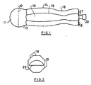
- the file handle shown in FIG. 1 begins in the region of its free end 11 with a partial spherical shape which continues over an equator 12 running perpendicular to the longitudinal axis of the handle to a constriction 13. From this constriction 13 on, the cross-sectional shape changes from a circular shape to a polygonal shape, see also FIG. 2. At the same time, the cross-section increases from the constriction 13 to approximately the middle of the longitudinal extent of the booklet, where a point 14 of maximum diameter is reached. To the This point is the diameter of the booklet practically the same size as at the equator 12 of the spherical end. Continuing to the opposite front end 15 of the booklet, the cross section of the booklet decreases again until another constriction 16 is reached at a point approximately in the front third to quarter of the booklet. From this constriction 16 on, the cross section increases again to the front end 15.
- the actual file 17 extends from the front end 15 and is only indicated in FIG. 1.
- the cross-sectional shape is formed by a regular polygon, in the example shown an octagon.
- the individual surfaces 18 of the outside of the booklet are separated from one another by edges 19 which are rounded.
- the upper and lower surfaces of the booklet in the position shown run parallel to the flat working surface 20 of the half-round file.
- the user of the file therefore has a certain feeling in his hand for where his work surface is and how it is oriented.
- the user can exert a force in both forward and downward direction on the handle by gripping the handle, in other words also a force obliquely to the longitudinal axis.
- the direction of this force can be changed within wide limits, with the advantage of uniform force distribution over a large area in the palm of the hand in all of these directions. The hand tired more slowly.
- the small and the ring fingers can be on the constriction 13 formed in the end region support, the front fingers of the hand also lying in the front constriction 16 and being able to guide the file. Because of the cross-sectional shape of the angular part of the file that deviates from the circular shape, the user can also exert good torques on the file, which can be necessary both for orienting the file and for exerting uneven pressure.
Landscapes
- Mechanical Engineering (AREA)
- Engineering & Computer Science (AREA)
- Sheet Holders (AREA)
- Measurement And Recording Of Electrical Phenomena And Electrical Characteristics Of The Living Body (AREA)
- Measuring Pulse, Heart Rate, Blood Pressure Or Blood Flow (AREA)
- Steering Devices For Bicycles And Motorcycles (AREA)
- Information Retrieval, Db Structures And Fs Structures Therefor (AREA)
- Pharmaceuticals Containing Other Organic And Inorganic Compounds (AREA)
- Stored Programmes (AREA)
- Milling, Broaching, Filing, Reaming, And Others (AREA)
- Walking Sticks, Umbrellas, And Fans (AREA)
- Fishing Rods (AREA)
- Food-Manufacturing Devices (AREA)
Abstract
Description
- Die Erfindung betrifft ein Feilenheft mit einer langgestreckten Form, die ein abgerundetes Ende und eine vordere Einschnürung im feilenseitigen Endbereich des Hefts aufweist.
- Feilen haben üblicherweise ein aus Holz oder Kunststoff bestehendes Heft, das eine langgestreckte Form aufweist. Im feilenseitigen Endbereich ist eine sehr flache Einschnürung vorhanden, während sich im Bereich des gegenüberliegenden freien Endes das Heft allmählich verjüngt, so daß eine zwar abgerundete, aber doch relativ schmale Endfläche gebildet wird. Der Griff hat üblicherweise einen kreisrunden Querschnitt.
- Bei sehr kleinen Feilen ist es auch schon bekannt, aus Kunststoff bestehende Hefte zu verwenden, die einen ovalen Griffschnitt aufweisen.
- Die Handhabung einer Feile muß unterschiedliche Anforderungen erfüllen. Feilen ab einer bestimmten Größe werden üblicherweise mit beiden Händen gehandhabt, wobei die eine Hand am Griff anfaßt. Dabei muß die Feile mit den Händen gesteuert werden, d.h. es muß eine bestimmte Orientierung der Feile, üblicherweise einer Bearbeitungsfläche der Feile, vorgegeben werden. Die Feile muß in ihrer Winkelstellung bzgl. dreier aufeinander senkrechter Achsen positioniert werden. Zusätzlich muß aber noch die eigentliche Feilbearbeitung durchgeführt werden, bei der während der Bewegung der Feile eine Kraft ausgeübt werden muß. Diese Kraft muß einmal in Bewegungsrichtung, üblicherweise der Vorschubrichtung, und aber auch in einer Richtung senkrecht zur Bearbeitungsfläche aufgebracht werden. Diesen unterschiedlichen Anforderungen werden die zur Zeit verwendeten Feilenhefte nicht gerecht.
- Der Erfindung liegt die Aufgabe zugrunde, ein Feilenheft zu schaffen, das den Bedürfnissen des Benutzers einer Feile besser angepaßt ist.
- Zur Lösung dieser Aufgabe schlägt die Erfindung vor, dem freien Ende des Feilenhefts etwa die Form mindestens einer halben Kugel zu geben, deren Durchmesser in einem Bereich von etwa 28 bis 32 mm liegt. Durch die Kugelform wird eine gut im Handteller liegende Form geschaffen, die zu einer Verringerung der Flächenbelastung und damit zu einem besseren und ermüdungsfreieren Einwirken der Hand auf die Feile führt. Aufgrund der Kugelform kann ein Druck nicht nur in Längsrichtung der Feile, also beim Schieben, sondern auch schräg zu dieser Richtung ausgeübt werden, so daß sich ein gutes Feilergebnis erzielen läßt.
- Erfindungsgemäß kann vorgesehen sein, daß das freie Ende des Feilenhefts die Form einer mehr als halben Kugel aufweist. Dies bedeutet, daß sich der Querschnitt des Feilenhefts nach dem Ende verringert, so daß das Ende einen größeren Teil als eine Halbkugel bildet. Dies schafft eine Anlagefläche für die Fingerspitze des kleinen und Ringfingers.
- In Weiterbildung kann vorgesehen sein, daß unmittelbar vor dem teilkugelförmigen Ende des Hefts eine Querschnittseinschnürung angeordnet ist. Auch diese kann zur Anlage des kleinen Fingers dienen. Die Griffigkeit des Heftes wird dadurch vergrößert. Dies ist insbesondere bei der Rückwärtsbewegung, also dem Ziehen der Feile von Wichtigkeit, da die Feile hier dann besser mitgenommen werden kann.
- In Weiterbildung der Erfindung kann vorgesehen sein, daß sich der Querschnitt des Hefts von der Endeinschnürung an bis zu einer Stelle eines lokalen Querschnittmaximums vergrößert, an der der Durchmesser des Hefts etwa dem Durchmesser des teilkugelförmigen Endes gleich ist. Diese Stelle des Durchmessermaximums liegt dabei erfindungsgemäß etwa in der Mitte der Längserstreckung des Heftes. Damit wird eine gute Lage des Griffes in der geschlossenen Hand erreicht. Diese gute Grifflage in der Hand ist für die Positionierung der Feile von Wichtigkeit.
- In Weiterbildung kann vorgesehen sein, daß der Querschnitt des Hefts von der Stelle des Querschnittmaximums bis zu der vorderen Einschnürung wieder abnimmt.
- Die Einschnürung dient zum Einlegen des Daumens. Die Erfindung schlägt nun vor, die an sich bekannte Einschnürung wesentlich deutlicher auszubilden, wobei beispielsweise mit Vorteil der größte Durchmesser um ca. 40 bis 50 % größer ist als der kleinste Durchmesser des Hefts.
- Erfindungsgemäß kann vorgesehen sein, daß der maximale Durchmesser des Hefts mindestens etwa ein Viertel der Länge des Hefts beträgt.
- Bei fast allen Arten von Feilen, allenfalls mit Ausnahme einer Rundfeile, muß während des Feilens eine bestimmte Orientierung der Feile durchgeführt werden. Um diese Möglichkeit zu verbessern, schlägt die Erfindung vor, daß der Querschnitt des Hefts von seinem feilenseitigen Ende bis zu der Endeinschnürung vor der Kugel mehreckig mit abgerundeten Kanten bzw. Ecken ausgebildet ist. Es fällt dem Benutzer aufgrund der mehrkantigen Form leichter, die Orientierung der Feile zu kontrollieren.
- In Weiterbildung kann vorgesehen sein, daß eine der Begrenzungsflächen des mehrkantigen Hefts parallel zu einer Arbeitsfläche der Feile verläuft.
- Weitere Merkmale, Einzelheiten und Vorzüge der Erfindung ergeben sich aus der folgenden Beschreibung einer bevorzugten Ausführungsform der Erfindung sowie anhand der Zeichnung. Hierbei zeigen:
- Fig. 1 eine Seitenansicht eines von der Erfindung vorgeschlagenen Feilenhefts;
- Fig. 2 schematisch eine Stirnansicht, die die gegenseitige Orientierung der Begrenzungsflächen des Hefts und der Flächen der Feile darstellt.
- Das in der Fig. 1 dargestellte Feilenheft beginnt im Bereich seines freien Endes 11 mit einer Teilkugelform, die sich über einen senkrecht zur Längsachse des Hefts verlaufenden Äquator 12 bis zu einer Einschnürung 13 fortsetzt. Von dieser Einschnürung 13 an wird die Querschnittsform von der Kreisform zu einer Mehrkantform, siehe auch Fig. 2. Gleichzeitig vergrößert sich der Querschnitt von der Einschnürung 13 bis etwa zu der Mitte der Längserstreckung des Heftes, wo eine Stelle 14 maximalen Durchmessers erreicht wird. An die ser Stelle ist der Durchmesser des Heftes praktisch gleich groß wie am Äquator 12 des kugelförmigen Endes. Weiter zum gegenüberliegenden vorderen Ende 15 des Hefts fortschreitend verringert sich der Querschnitt des Hefts wieder, bis an einer Stelle etwa im vorderen Drittel bis Viertel des Hefts eine weitere Einschnürung 16 erreicht wird. Von dieser Einschnürung 16 an vergrößert sich der Querschnitt wieder bis zum vorderen Ende 15.
- Vom vorderen Ende 15 aus erstreckt sich die eigentliche Feile 17, die in Fig. 1 nur angedeutet ist.
- Mit Ausnahme des kugelförmigen Endes ist die Querschnittsform von einem regelmäßigen Vieleck, im dargestellten Beispiel einem Achteck, gebildet. Die einzelnen Flächen 18 der Außenseite des Hefts werden durch Kanten 19 voneinander getrennt, die abgerundet verlaufen.
- Wie sich aus Fig. 2 ergibt, verläuft jeweils die obere und untere Fläche des Hefts in der dargestellten Stellung parallel zu der ebenen Arbeitsfläche 20 der Halbrundfeile. Der Benutzer der Feile hat daher in der Hand ein gewisses Gefühl dafür, wo seine Arbeitsfläche liegt und wie sie orientiert ist.
- Wenn man annimmt, daß bei der Darstellung der Fig. 1 die Arbeitsfläche 20 auf der Unterseite der Feile ist, so kann der Benutzer durch Angreifen an dem Heft eine Kraft sowohl in Vorwärtsrichtung als auch in Abwärtsrichtung auf das Heft ausüben, anders ausgedrückt auch eine Kraft schräg zur Längsachse. Die Richtung dieser Kraft ist in weiten Grenzen veränderbar, wobei in allen diesen Richtungen der Vorteil einer gleichmäßigen Kraftverteilung auf eine große Fläche im Handteller gegeben ist. Die Hand ermüdet also langsamer. Beim Zurückziehen der Feile können sich der kleine und der Ringfinger an der im Endbereich gebildeten Einschnürung 13 abstützen, wobei gleichzeitig auch die Vorderfinger der Hand in der vorderen Einschnürung 16 liegen und die Feile führen können. Aufgrund der von der Kreisform abweichenden Querschnittsform des kantigen Teils der Feile kann der Benutzer auch gut Drehmomente auf die Feile ausüben, was sowohl zur Orientierung der Feile als auch zur Ausübung von ungleichmäßigem Druck erforderlich sein kann.
Claims (11)
Applications Claiming Priority (2)
| Application Number | Priority Date | Filing Date | Title |
|---|---|---|---|
| DE3926902 | 1989-08-16 | ||
| DE3926902A DE3926902A1 (de) | 1989-08-16 | 1989-08-16 | Feilenheft |
Publications (2)
| Publication Number | Publication Date |
|---|---|
| EP0413202A1 true EP0413202A1 (de) | 1991-02-20 |
| EP0413202B1 EP0413202B1 (de) | 1994-07-06 |
Family
ID=6387142
Family Applications (1)
| Application Number | Title | Priority Date | Filing Date |
|---|---|---|---|
| EP90114806A Expired - Lifetime EP0413202B1 (de) | 1989-08-16 | 1990-08-02 | Feilenheft |
Country Status (5)
| Country | Link |
|---|---|
| EP (1) | EP0413202B1 (de) |
| AT (1) | ATE108120T1 (de) |
| DE (2) | DE3926902A1 (de) |
| DK (1) | DK0413202T3 (de) |
| ES (1) | ES2056315T3 (de) |
Cited By (2)
| Publication number | Priority date | Publication date | Assignee | Title |
|---|---|---|---|---|
| EP0510298A1 (de) * | 1991-04-17 | 1992-10-28 | MARTOR-ARGENTAX E.H. Beermann KG | Messer, insbesondere Entgratemesser für Kunststoffteile |
| WO2006097181A1 (de) | 2005-03-18 | 2006-09-21 | Carl Freudenberg Kg | Handhabungselement für ein reinigungsgerät |
Citations (12)
| Publication number | Priority date | Publication date | Assignee | Title |
|---|---|---|---|---|
| US2056054A (en) * | 1934-07-18 | 1936-09-29 | John L Osgood | Tool handle |
| US2351705A (en) * | 1942-12-09 | 1944-06-20 | Prall Gustav | Screw driver |
| US2377745A (en) * | 1944-04-18 | 1945-06-05 | Belanger Emile | Handle guide |
| FR1494869A (fr) * | 1966-08-01 | 1967-09-15 | Ciseau-burin chirurgical pour la décortication des os | |
| DE1806976A1 (de) * | 1968-11-05 | 1970-08-13 | Walter Finkeldei Werkzeugfabri | Insbesondere fuer Drillschrauber bestimmtes Werkzeugheft |
| DE1944008A1 (de) * | 1969-08-29 | 1971-03-04 | Herbert Pilat | Handgriff fuer Schraubenzieher |
| NL7117611A (de) * | 1970-12-21 | 1972-06-23 | ||
| DE2452302A1 (de) * | 1974-11-05 | 1976-05-06 | Weber Fa Gustav | Griff fuer handwerkzeuge, insbesondere schraubendreher |
| DE3004957A1 (de) * | 1980-02-09 | 1981-08-20 | Fa. W. Holland-Letz, 5608 Radevormwald | Griff fuer einhaddrehwerkzeuge |
| EP0062270A2 (de) * | 1981-04-08 | 1982-10-13 | Elora-Werkzeugfabrik GmbH | Werkzeugheft |
| FR2515561A1 (fr) * | 1981-10-29 | 1983-05-06 | Lux Gmbh & Co Kg Emil | Manche de lime |
| DE8914014U1 (de) * | 1989-11-28 | 1990-02-08 | Lauber, Manfred, 3560 Biedenkopf | Werkzeuggriff für Schraubendreher |
Family Cites Families (5)
| Publication number | Priority date | Publication date | Assignee | Title |
|---|---|---|---|---|
| AT210843B (de) * | 1959-01-27 | 1960-08-25 | Michael Ing Stiebellehner | Heft für Feilen od. dgl. |
| DE1871199U (de) * | 1963-01-23 | 1963-04-25 | Hermann Csismarics | Feilenheft. |
| DE1972899U (de) * | 1965-06-18 | 1967-11-16 | Wuro Werkzeuge Kunststoffe Wil | Schraubenzieher. |
| DE3151870A1 (de) * | 1981-12-30 | 1983-07-21 | Felo Holland-Letz GmbH & Co KG, 3577 Neustadt | Werkzeuggriff, insbesondere schraubendrehergriff |
| DE8317313U1 (de) * | 1983-06-14 | 1984-02-09 | Felo Holland-Letz GmbH & Co KG, 3577 Neustadt | Werkzeugheft aus kunststoff, insbesondere fuer schraubendreher |
-
1989
- 1989-08-16 DE DE3926902A patent/DE3926902A1/de not_active Ceased
-
1990
- 1990-08-02 ES ES90114806T patent/ES2056315T3/es not_active Expired - Lifetime
- 1990-08-02 EP EP90114806A patent/EP0413202B1/de not_active Expired - Lifetime
- 1990-08-02 DK DK90114806.4T patent/DK0413202T3/da active
- 1990-08-02 AT AT90114806T patent/ATE108120T1/de not_active IP Right Cessation
- 1990-08-02 DE DE59006347T patent/DE59006347D1/de not_active Expired - Fee Related
Patent Citations (12)
| Publication number | Priority date | Publication date | Assignee | Title |
|---|---|---|---|---|
| US2056054A (en) * | 1934-07-18 | 1936-09-29 | John L Osgood | Tool handle |
| US2351705A (en) * | 1942-12-09 | 1944-06-20 | Prall Gustav | Screw driver |
| US2377745A (en) * | 1944-04-18 | 1945-06-05 | Belanger Emile | Handle guide |
| FR1494869A (fr) * | 1966-08-01 | 1967-09-15 | Ciseau-burin chirurgical pour la décortication des os | |
| DE1806976A1 (de) * | 1968-11-05 | 1970-08-13 | Walter Finkeldei Werkzeugfabri | Insbesondere fuer Drillschrauber bestimmtes Werkzeugheft |
| DE1944008A1 (de) * | 1969-08-29 | 1971-03-04 | Herbert Pilat | Handgriff fuer Schraubenzieher |
| NL7117611A (de) * | 1970-12-21 | 1972-06-23 | ||
| DE2452302A1 (de) * | 1974-11-05 | 1976-05-06 | Weber Fa Gustav | Griff fuer handwerkzeuge, insbesondere schraubendreher |
| DE3004957A1 (de) * | 1980-02-09 | 1981-08-20 | Fa. W. Holland-Letz, 5608 Radevormwald | Griff fuer einhaddrehwerkzeuge |
| EP0062270A2 (de) * | 1981-04-08 | 1982-10-13 | Elora-Werkzeugfabrik GmbH | Werkzeugheft |
| FR2515561A1 (fr) * | 1981-10-29 | 1983-05-06 | Lux Gmbh & Co Kg Emil | Manche de lime |
| DE8914014U1 (de) * | 1989-11-28 | 1990-02-08 | Lauber, Manfred, 3560 Biedenkopf | Werkzeuggriff für Schraubendreher |
Cited By (2)
| Publication number | Priority date | Publication date | Assignee | Title |
|---|---|---|---|---|
| EP0510298A1 (de) * | 1991-04-17 | 1992-10-28 | MARTOR-ARGENTAX E.H. Beermann KG | Messer, insbesondere Entgratemesser für Kunststoffteile |
| WO2006097181A1 (de) | 2005-03-18 | 2006-09-21 | Carl Freudenberg Kg | Handhabungselement für ein reinigungsgerät |
Also Published As
| Publication number | Publication date |
|---|---|
| EP0413202B1 (de) | 1994-07-06 |
| ES2056315T3 (es) | 1994-10-01 |
| ATE108120T1 (de) | 1994-07-15 |
| DE3926902A1 (de) | 1991-02-21 |
| DE59006347D1 (de) | 1994-08-11 |
| DK0413202T3 (da) | 1994-11-07 |
Similar Documents
| Publication | Publication Date | Title |
|---|---|---|
| EP0090256B1 (de) | Werkzeuggriff für eine darin insbesondere längsverschiebliche Messerklinge | |
| WO1989010244A1 (fr) | Ciseaux, notamment ciseaux de coiffeur | |
| DE69929921T2 (de) | Zahnwurzelkanalinstrument | |
| DE2606461B2 (de) | Handhabe fuer ein motorisches schlagwerkzeug, insbesondere einen bohrhammer | |
| DE3110945C2 (de) | Glasschneider | |
| DE3023057C2 (de) | Schere | |
| DE69721543T2 (de) | Vorrichtung zum betrieb eines maus-gesteuerten programms | |
| EP0062270B1 (de) | Werkzeugheft | |
| EP0413202B1 (de) | Feilenheft | |
| DE2926556A1 (de) | Werkzeughalter, vorzugsweise fuer zahntechnische zwecke | |
| DE19909224A1 (de) | Montagezange mit verstellbarer Maulweite | |
| DE69204883T2 (de) | Werkzeuggriff, insbesondere für Präzisionsschraubendreher, und entsprechende Werkzeuge. | |
| EP0593906A2 (de) | Schraubendreher Handgriff | |
| DE2800796C3 (de) | Griff für Handgeräte | |
| DE3029910A1 (de) | Handschere mit einer einstellbaren lagerkonstruktion | |
| EP0330173A1 (de) | Zahnwurzelbearbeitungsinstrument | |
| EP4151376B9 (de) | Schere | |
| DE8716099U1 (de) | Schraubendreher | |
| EP1277550A1 (de) | Handschere | |
| DE9312957U1 (de) | Schraubendreher | |
| AT395552B (de) | Kombinations-haarschneideschere | |
| DE69406031T2 (de) | Schraubenzieher | |
| DE10001418B4 (de) | Pinzette | |
| DE8203535U1 (de) | Schraubendreher | |
| DE2904898A1 (de) | Blatt-tragendes handwerkzeug, wie kelle oder spachtel |
Legal Events
| Date | Code | Title | Description |
|---|---|---|---|
| PUAI | Public reference made under article 153(3) epc to a published international application that has entered the european phase |
Free format text: ORIGINAL CODE: 0009012 |
|
| 17P | Request for examination filed |
Effective date: 19901212 |
|
| AK | Designated contracting states |
Kind code of ref document: A1 Designated state(s): AT BE CH DE DK ES FR GB GR IT LI LU NL SE |
|
| 17Q | First examination report despatched |
Effective date: 19921208 |
|
| GRAA | (expected) grant |
Free format text: ORIGINAL CODE: 0009210 |
|
| AK | Designated contracting states |
Kind code of ref document: B1 Designated state(s): AT BE CH DE DK ES FR GB GR IT LI LU NL SE |
|
| REF | Corresponds to: |
Ref document number: 108120 Country of ref document: AT Date of ref document: 19940715 Kind code of ref document: T |
|
| REF | Corresponds to: |
Ref document number: 59006347 Country of ref document: DE Date of ref document: 19940811 |
|
| ET | Fr: translation filed | ||
| GBT | Gb: translation of ep patent filed (gb section 77(6)(a)/1977) |
Effective date: 19940810 |
|
| ITF | It: translation for a ep patent filed | ||
| REG | Reference to a national code |
Ref country code: ES Ref legal event code: FG2A Ref document number: 2056315 Country of ref document: ES Kind code of ref document: T3 |
|
| REG | Reference to a national code |
Ref country code: DK Ref legal event code: T3 |
|
| REG | Reference to a national code |
Ref country code: GR Ref legal event code: FG4A Free format text: 3013473 |
|
| EAL | Se: european patent in force in sweden |
Ref document number: 90114806.4 |
|
| PLBE | No opposition filed within time limit |
Free format text: ORIGINAL CODE: 0009261 |
|
| STAA | Information on the status of an ep patent application or granted ep patent |
Free format text: STATUS: NO OPPOSITION FILED WITHIN TIME LIMIT |
|
| 26N | No opposition filed | ||
| PGFP | Annual fee paid to national office [announced via postgrant information from national office to epo] |
Ref country code: GB Payment date: 20000727 Year of fee payment: 11 |
|
| PGFP | Annual fee paid to national office [announced via postgrant information from national office to epo] |
Ref country code: FR Payment date: 20000817 Year of fee payment: 11 |
|
| PGFP | Annual fee paid to national office [announced via postgrant information from national office to epo] |
Ref country code: ES Payment date: 20000822 Year of fee payment: 11 |
|
| PGFP | Annual fee paid to national office [announced via postgrant information from national office to epo] |
Ref country code: GR Payment date: 20000823 Year of fee payment: 11 |
|
| PGFP | Annual fee paid to national office [announced via postgrant information from national office to epo] |
Ref country code: NL Payment date: 20000824 Year of fee payment: 11 Ref country code: CH Payment date: 20000824 Year of fee payment: 11 Ref country code: BE Payment date: 20000824 Year of fee payment: 11 Ref country code: AT Payment date: 20000824 Year of fee payment: 11 |
|
| PGFP | Annual fee paid to national office [announced via postgrant information from national office to epo] |
Ref country code: SE Payment date: 20000825 Year of fee payment: 11 |
|
| PGFP | Annual fee paid to national office [announced via postgrant information from national office to epo] |
Ref country code: DK Payment date: 20000828 Year of fee payment: 11 |
|
| PGFP | Annual fee paid to national office [announced via postgrant information from national office to epo] |
Ref country code: LU Payment date: 20000830 Year of fee payment: 11 |
|
| PGFP | Annual fee paid to national office [announced via postgrant information from national office to epo] |
Ref country code: DE Payment date: 20001014 Year of fee payment: 11 |
|
| PG25 | Lapsed in a contracting state [announced via postgrant information from national office to epo] |
Ref country code: LU Free format text: LAPSE BECAUSE OF NON-PAYMENT OF DUE FEES Effective date: 20010802 Ref country code: GB Free format text: LAPSE BECAUSE OF NON-PAYMENT OF DUE FEES Effective date: 20010802 Ref country code: DK Free format text: LAPSE BECAUSE OF NON-PAYMENT OF DUE FEES Effective date: 20010802 Ref country code: AT Free format text: LAPSE BECAUSE OF NON-PAYMENT OF DUE FEES Effective date: 20010802 |
|
| PG25 | Lapsed in a contracting state [announced via postgrant information from national office to epo] |
Ref country code: SE Free format text: LAPSE BECAUSE OF NON-PAYMENT OF DUE FEES Effective date: 20010803 Ref country code: ES Free format text: LAPSE BECAUSE OF NON-PAYMENT OF DUE FEES Effective date: 20010803 |
|
| PG25 | Lapsed in a contracting state [announced via postgrant information from national office to epo] |
Ref country code: LI Free format text: LAPSE BECAUSE OF NON-PAYMENT OF DUE FEES Effective date: 20010831 Ref country code: CH Free format text: LAPSE BECAUSE OF NON-PAYMENT OF DUE FEES Effective date: 20010831 Ref country code: BE Free format text: LAPSE BECAUSE OF NON-PAYMENT OF DUE FEES Effective date: 20010831 |
|
| PG25 | Lapsed in a contracting state [announced via postgrant information from national office to epo] |
Ref country code: GR Free format text: LAPSE BECAUSE OF NON-PAYMENT OF DUE FEES Effective date: 20020209 |
|
| BERE | Be: lapsed |
Owner name: ADOLF WURTH G.M.B.H. & CO. K.G. Effective date: 20010831 |
|
| PG25 | Lapsed in a contracting state [announced via postgrant information from national office to epo] |
Ref country code: NL Free format text: LAPSE BECAUSE OF NON-PAYMENT OF DUE FEES Effective date: 20020301 |
|
| GBPC | Gb: european patent ceased through non-payment of renewal fee |
Effective date: 20010802 |
|
| EUG | Se: european patent has lapsed |
Ref document number: 90114806.4 |
|
| REG | Reference to a national code |
Ref country code: CH Ref legal event code: PL |
|
| REG | Reference to a national code |
Ref country code: DK Ref legal event code: EBP |
|
| PG25 | Lapsed in a contracting state [announced via postgrant information from national office to epo] |
Ref country code: FR Free format text: LAPSE BECAUSE OF NON-PAYMENT OF DUE FEES Effective date: 20020430 |
|
| NLV4 | Nl: lapsed or anulled due to non-payment of the annual fee |
Effective date: 20020301 |
|
| PG25 | Lapsed in a contracting state [announced via postgrant information from national office to epo] |
Ref country code: DE Free format text: LAPSE BECAUSE OF NON-PAYMENT OF DUE FEES Effective date: 20020501 |
|
| REG | Reference to a national code |
Ref country code: FR Ref legal event code: ST |
|
| REG | Reference to a national code |
Ref country code: ES Ref legal event code: FD2A Effective date: 20020911 |
|
| PG25 | Lapsed in a contracting state [announced via postgrant information from national office to epo] |
Ref country code: IT Free format text: LAPSE BECAUSE OF NON-PAYMENT OF DUE FEES;WARNING: LAPSES OF ITALIAN PATENTS WITH EFFECTIVE DATE BEFORE 2007 MAY HAVE OCCURRED AT ANY TIME BEFORE 2007. THE CORRECT EFFECTIVE DATE MAY BE DIFFERENT FROM THE ONE RECORDED. Effective date: 20050802 |