EP0413286B1 - Système de transmission synchrone de données pour interface d'échange de données à fibres distribuées - Google Patents
Système de transmission synchrone de données pour interface d'échange de données à fibres distribuées Download PDFInfo
- Publication number
- EP0413286B1 EP0413286B1 EP90115510A EP90115510A EP0413286B1 EP 0413286 B1 EP0413286 B1 EP 0413286B1 EP 90115510 A EP90115510 A EP 90115510A EP 90115510 A EP90115510 A EP 90115510A EP 0413286 B1 EP0413286 B1 EP 0413286B1
- Authority
- EP
- European Patent Office
- Prior art keywords
- transfer
- data
- time
- synchronous
- synchronization
- Prior art date
- Legal status (The legal status is an assumption and is not a legal conclusion. Google has not performed a legal analysis and makes no representation as to the accuracy of the status listed.)
- Expired - Lifetime
Links
- 230000001360 synchronised effect Effects 0.000 title claims description 95
- 239000000835 fiber Substances 0.000 title claims description 5
- 238000001514 detection method Methods 0.000 claims description 29
- 230000006870 function Effects 0.000 claims description 20
- 230000005540 biological transmission Effects 0.000 claims description 13
- 230000007274 generation of a signal involved in cell-cell signaling Effects 0.000 claims description 13
- 238000006243 chemical reaction Methods 0.000 claims description 9
- 239000013307 optical fiber Substances 0.000 claims description 8
- 238000000034 method Methods 0.000 description 19
- 125000004122 cyclic group Chemical group 0.000 description 10
- 238000010586 diagram Methods 0.000 description 7
- 230000001186 cumulative effect Effects 0.000 description 4
- 230000003287 optical effect Effects 0.000 description 4
- 238000005070 sampling Methods 0.000 description 4
- 230000002123 temporal effect Effects 0.000 description 4
- 230000002093 peripheral effect Effects 0.000 description 3
- 101100497196 Arabidopsis thaliana CPN60B1 gene Proteins 0.000 description 2
- 230000005856 abnormality Effects 0.000 description 2
- 230000001276 controlling effect Effects 0.000 description 2
- 230000003111 delayed effect Effects 0.000 description 2
- 238000004519 manufacturing process Methods 0.000 description 1
- 230000001105 regulatory effect Effects 0.000 description 1
- 239000004065 semiconductor Substances 0.000 description 1
- 238000000926 separation method Methods 0.000 description 1
Images


Classifications
-
- H—ELECTRICITY
- H04—ELECTRIC COMMUNICATION TECHNIQUE
- H04L—TRANSMISSION OF DIGITAL INFORMATION, e.g. TELEGRAPHIC COMMUNICATION
- H04L12/00—Data switching networks
- H04L12/64—Hybrid switching systems
-
- H—ELECTRICITY
- H04—ELECTRIC COMMUNICATION TECHNIQUE
- H04L—TRANSMISSION OF DIGITAL INFORMATION, e.g. TELEGRAPHIC COMMUNICATION
- H04L12/00—Data switching networks
- H04L12/28—Data switching networks characterised by path configuration, e.g. LAN [Local Area Networks] or WAN [Wide Area Networks]
- H04L12/42—Loop networks
- H04L12/427—Loop networks with decentralised control
- H04L12/433—Loop networks with decentralised control with asynchronous transmission, e.g. token ring, register insertion
Definitions
- the present invention relates to synchronous data transfer systems according to the preamble of claim 1 (EP-A-0 245 765).
- Such a system comprises nodes provided to data processing apparatus or peripheral apparatus and disposed at a plural number of points which are mutually separated by a certain distance, and optical transfer cables connecting those control apparatus, and provided with a fiber distributed data exchange interface (hereinafter termed an FDDI) that can be used for optical local area networks to transmit/receive at either high speed or low speed, various types of data between said processing apparatus and/or control apparatus, and peripheral apparatus, and relates to data synchronous transfer methods that have circuit exchange functions such as the cyclic performing of data exchange between control apparatus at a plural number of mutually remote locations, the simultaneous sampling of process data such as instantaneous values such as voltage, current and the like at a plural number of mutually remote locations, the enabling of data transfer for so that a plural number of computers and control apparatus are connected with all processing apparatus performing data processing in temporal synchronization, and that can transfer data such as the voice data necessary for cyclic transfer, and the like.
- FDDI fiber distributed data exchange interface
- LAN networks local area networks
- ANSI-FDDI fiber distributed data exchange interfaces for which standardization has been defined by the American National Standards Institute (hereinafter, termed ANSI-FDDI).
- ANSI-FDDI use optical fiber as the transfer path and are 100 Mbps ring-shaped LAN that use the token passing method as the transfer control method.
- FDDI field-definition data-definition
- MAP machine learning automation protocol
- MAP is a communications protocol for the automization of factories and is the practical standard for LAN for factory automation purposes (known as FA-LAN).
- LAN using FDDI having a plural number of nodes mutually connected in a ring shape generally have various functions such as transfer path control functions that can stop transfer requests from each node, in accordance with the transfer region that can be used by the network and acquire transfer path usage rights, transfer and receive function for the data from each node, transfer system obstruction detection functions, obstruction portion separation functions, and transfer system reconfiguration functions, etc.
- token-passing LAN used for LAN having FDDI
- transfer rights known as tokens are successively received between each of the nodes in the system to prevent a plural number of nodes from sending at the same time.
- These systems are configured so that date can be sent within a predetermined set time, by those nodes that have received tokens. Accordingly, it is possible to have definitive transfer path access and so this token passing method is used in MAP systems that require realtime control.
- a data transfer system that has the data packet exchange functions conventionally provided, and for it to additionally have circuit exchange functions such as the cyclic performing of data exchange between control apparatus at a plural number of mutually remote locations, the simultaneous sampling of process data such as instantaneous values such as voltage, current and the like at a plural number of mutually remote locations, the enabling of data transfer for so that a plural number of computers and control apparatus are connected with all processing apparatus performing data processing in temporal synchronization, and that can transfer data such as the voice data necessary for cyclic transfer, and the like.
- An object of the present invention is for when a ring-shaped high-speed LAN using a FDDI which is the powerful standard for the next generation of high-speed and wide-area LAN, is used to transfer data, to provide the data packet exchange functions conventionally provided, and for it to additionally have circuit exchange functions such as the cyclic performing of data exchange between control apparatus at a plural number of mutually remote locations, the simultaneous sampling of process data such as instantaneous values such as voltage, current and the like at a plural number of mutually remote locations, the enabling of data transfer for so that a plural number of computers and control apparatus are connected with all processing apparatus performing data processing in temporal synchronization, and that can transfer data such as the voice data necessary for cyclic transfer, and the like, all without losing the excellent reliability, self-recoverability and extendability that are the conventional characteristics of FDDI.
- FDDI which is the powerful standard for the next generation of high-speed and wide-area LAN
- the data synchronous transfer apparatus relating to the present invention is a data synchronous transfer apparatus X in which data processing apparatus having fiber distributed data interfaces provided with processing functions for synchronous services and asynchronous services are disposed at each node, and in which these nodes are connected via transfer paths into a ring shape and transmit and receive data
- the data synchronous transfer apparatus relating to the present invention is characterized in that the nodes that are the primary stations for synchronizing the time of the synchronous data frames are provided with a synchronization signal generation circuit that generates a synchronization signal for each set time an external time signal is received from either itself or externally, a token detection circuit in order to detect the receipt of a token that rotates around a transfer path connected in a ring shape, and a counter that counts down a predetermined value and that is reset for each generation of the synchronization signal, a frame length conversion circuit, that creates a dummy data frame having a time equivalent in
- the method of transfer of data synchronized with a set time and using a LAN system using FDDI special nodes in the LAN system are made primary nodes, and when these primary station nodes perform data frame transfer in agreement with a cyclically set time, the data frames of the primary stations are received at the nodes other than those special nodes, that is to say, at the nodes of the secondary stations, and it is possible to know the set time by calculating back from the time of receipt, so that it is possible to perform synchronization of the times for all nodes that are participating in the LAN system network.
- the nodes of the primary stations set a data frame that is to be transferred synchronous with the set time as synchronous data frame Ds, and the transfer start timing of the synchronous data frame Ds is made to coincide with the set time.
- the asynchronous service functions and the synchronous service function of FDDI are used so to transfer a fixed quantity of data constantly, and also to transfer a variable quantity of data in accordance with data transfer requests that generate suddenly, so that changes occur in the data frame transfer time at each node so that as a result, the token rotation time TRT changes at the nodes of the primary stations. Accordingly, it becomes necessary to have a source time adjustment means in order to transfer the synchronous data frames so that the nodes of the primary station are in agreement with the set time.
- the dummy data frame Dm is set prior to the sending of a synchronous data frame Ds when there is the receipt of a token that has made one rotation.
- the data length of the dummy data frame DM that is to be transferred is determined in that the data length of the dummy data frame Dm that is to be sent is adjusted in accordance with the set time at which the synchronous data frame is to be transferred and the time difference.
- the dummy data frame Dm for which this has been done is transferred prior to the transfer of the synchronous data frame Ds, and then the synchronous data frame Ds is transferred, the transfer start time of the synchronous data frame Ds is made in agreement with the set time, that is to say, it is synchronized and transferred cyclically.
- the data length of the dummy data frame Dm is adjusted for each time and doing this controls the transfer start time of the synchronous data frame Ds that is transferred from the node of the primary station so that it becomes the set time, and cumulative time errors are thus cancelled.
- the total amount of data that is transferred using the synchronous service and the asynchronous service within the set time cycle Th is limited to the value that can transfer the dummy data frame Dm for the adjustment of the transfer start time of the synchronous data frame Ds.
- the data synchronous transfer method of the present invention when a token that has made one rotation is received at a node, and when there is a time discrepancy with respect to the set time, of the transfer time of a synchronous data frame that is to be transferred, a dummy data frame having a length according to the time difference with the set time for the transfer of the synchronous data frame is transferred so that in addition to the data packet exchange functions conventionally provided for ring-shaped high-speed LAN using FDDI, it is possible to provide the data packet exchange functions conventionally provided, and for it to additionally have circuit exchange functions such as the cyclic performing of data exchange between control apparatus at a plural number of mutually remote locations, the simultaneous sampling of process data such as instantaneous values such as voltage, current and the like at a plural number of mutually remote locations, the enabling of data transfer for so that a plural number of computers and control apparatus are connected with all processing apparatus performing data processing in temporal synchronization, and that can transfer data such as the voice data necessary for
- LAN using FDDI have the two types of services of a synchronous service and an asynchronous service.
- the synchronous service can send the received token and a synchronous frame at any time.
- the nodes can send an asynchronous frame that is not synchronized with the receipt of the token, only when the tokens are circulating sufficiently quickly.
- TTRT target token rotation times
- the current value in the timer TRT is reset to the TOPR value and the timer TRT is restarted.
- the transfer of the asynchronous frame in the time equivalent to the above described current value set in the timer TRT it is possible for the transfer of the asynchronous frame in the time equivalent to the above described current value set in the timer TRT.
- the token is passed to the next node when this current value set in the timer TRT has elapsed, and when there is no asynchronous frame that is to be sent.
- the timer TRT is not reset irrespective of whether the rate counter is reset. In this case, the transfer of only synchronous frames is permitted and the token is passed to the next node after the transfer of the asynchronous frame has been completed.
- a number from #1 to #n of nodes N 1 through N n are mutually connected by two optical fiber cables L 1 and L 2 so that the directions of the transfer data flows oppose each other.
- Each of these #1 to #n nodes N 1 through N n are configured by a transfer control unit 10 that controls the data transfer and a host apparatus 30 that connects them.
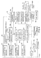
- This transfer control unit 10 is as indicated in FIG. 4.
- the transfer control unit 10 is provided with an arbitration circuit (ARBT) 11, a transferring and receiving control circuit (TRC) 12, optical transceivers (OTR1, OTR2) 13a, 13b, a synchronization discrepancy detection circuit 14, a transfer start detection circuit 15, token receipt detection circuit 16, a buffer memory circuit (BRAM) 17, a synchronization signal generation circuit 18, a Cm counter 19, a timer value hold circuit 20, a limiter circuit 21, a LENm register 22, a limit value setting register 23, a Cm counter value setting register 24, a synchronization time cycle setting register 25, a transmission circuit 26, a synchronization range setting register 27, a microprocessor 28 for the FDDI and a memory circuit 29 for the program.
- the host machine 30 is connected to the transfer control unit 10 via an interface control circuit 31.
- the data transfer and receiving control circuit 12 is a circuit that controls the transfer and receiving of data on the basis of the FDDI ratings, and this data transfer and receiving control circuit 12 is a circuit with a configuration equivalent to the Am79C81A Am79C82A, Am79C83, Am7984A and Am7985A of the American company AMD.
- the optical transceivers 13a and 13b are for the transfer and receiving of data to and from the transfer path.
- the synchronization discrepancy detection circuit 14 detects synchronization discrepancies between the transfer start signal 15a input from the transfer start detection circuit 15 and the synchronization discrepancy detection signal 18a amongst the external time signals output from the synchronization signal generation circuit 18 and sends the detection signal 14a to the microprocessor 28 for the FDDI as an interrupt signal when a discrepancy is detected.
- the transfer start detection circuit 15 is a circuit for detecting the transfer start of transfer data from the transferring and receiving control circuit (TRC) 12, to the transfer path.
- the token receipt detection circuit 16 detects the receipt of a token and therefore the buffer memory circuit (BRAM) 17 stores the transfer data that is sent and received.
- the synchronization signal generation circuit 18 is provided at each node which is a primary station and the external time signals S ext that are externally input, or the timing signals from the transmission circuit 26 are input to it, and the synchronization signals S r that become the standard are generated. These synchronization signals S r are detected when the external time signals S ext are received externally, and the external time signals S ext are detected when there is no longer the set cycle T h that has been set beforehand.
- the synchronization signal generation circuit 18 When this is detected, the synchronization signal generation circuit 18 outputs synchronization discrepancy abnormality detection signals, that is, the synchronization discrepancy detection signals 18a, and also has a function to generate synchronization signals having the set cycle T h , by itself and so these synchronization signals S r that have been internally generated are used for reference timing of the transfer start time of the synchronization data frame that the primary node is to transfer.
- the Cm counter 19 is reset for each synchronization signal S r from the synchronization signal generation circuit 18 and also counts down the set cycle T h +a that is set by the Cm counter value register to be described later, and therefore, this set cycle T h +a is controlled so that it is generated for each set cycle T h (and which changes by set cycle T h ⁇ where there is tracking of the external synchronization signal) and so is a time larger than the synchronization signal S r by the time a. This is to say that the Cm counter 19 there is no overcount for the set cycle T h . (Refer to FIG. 5.)
- the timer value hold circuit 20 holds and stores the count value that was counted down by the Cm counter 19 at the timing of the receipt of the token, and the timer value hold circuit 20 which is the frame length conversion circuit converts the time value equivalent to the count value of the Cm counter 19 and which is held and stored in the timer value hold circuit 20, into the dummy data frame and also places a limit on the conversion length of this dummy data frame.
- the LENm register 22 gives the number of words for transfer for the transfer control word indicated in FIG. 6 and corresponding to the delimited frame length from the limiter circuit 21 and so the limit value setting register 23 sets the limit value of the limiter circuit 21.
- the Cm counter value setting register 24 is for setting the count value equivalent to the previously described set cycle T h +a in the Cm counter 19, and the synchronization time cycle setting register 25 is for setting the cycle time value in the synchronization signal generation circuit 18.
- the transmission circuit 26 gives a timing signal for the set time, to the synchronization signal generation circuit 18 and so the synchronization range setting register 27 is for setting the detection range value for the synchronization discrepancy of the synchronization discrepancy detection circuit 14.
- the microprocessor 28 for the FDDI governs the transfer control of the data and therefore the memory circuit 29 for the program is for giving the program for the data transfer, to the microprocessor 28 for the FDDI, and the interface control circuit 31 is for controlling the interface between the host machine 30 connected to the nodes.
- arbitration circuit (ARBT) 11 performs the stop of access rights when there the host machine 30 and the transferring and receiving control circuit (TRC) 12, and the P-bus side connected to the microprocessor 28 for the FDDI, access to the buffer memory circuit (BRAM) 17 that stores the data for send and receive.
- a data synchronous transfer system of the present invention which is performed by LAN provided at each node with transfer control portions having the configuration described above
- the total amounts of data of the entire LAN system having an FDDI and a synchronous service for the transfer of H (high-speed) level synchronous data and an asynchronous service for the transfer of M (low-speed) level asynchronous data are made dh and dm respectively, and the time necessary for their respective transfer, that is the times taken by the data as transfer data frames on the LAN are made T dh and T dm .
- T dh and T dm the time taken on the transfer path for the tokens to be passed between nodes.
- the times T hm and T mm are respectively the times necessary for the transfer of data of the M level and the synchronous data of the H level and for which sudden transfer requests have been generated using the asynchronous service and the synchronous service, and the time T h is the set cycle time determined by a method to be described later. (Refer to FIG. 7.).
- the time T v means a vacant time when there is no data on the transfer path and is determined by the length of the cable around the ring, or by the number of time data is relayed for each node in the LAN.
- the vacant time T v on an optical fiber transfer path is determined as indicated in FIG. 8, by the transmission delay time required for a transferred data frame to make one rotation around the ring.
- T sd (i) is the data frame relay delay at the node i
- T hm T dh + T dm + T v + T hm + T mm + T n2
- T n1 > T n2
- the time T hm for the transfer of the synchronous data of the H level and for which there was sudden transfer request by the synchronous service is limited by the data lengths transferred at each node
- the time T mm for the transfer of the asynchronous data of the M level and for which there was sudden transfer request by the asynchronous service is limited by the data lengths transferred at each node
- the token rotation time specified by the asynchronous service is also the set cycle time T h or less.
- the LAN uses an FDDI and in this LAN, the controlling the transfer of the data frame at the transferring and receiving control circuit (TRC) 12 involves setting the transfer control word that specifies and controls each of the data frames that are to be sent as indicated in FIG. 6, in the buffer memory circuit (BRAM) 17 and then using this to perform transfer operation for the data.
- TRC transferring and receiving control circuit
- the dummy data frame is a data frame for initial transfer upon the receipt of the token and so the LEN 1 within the transfer control word indicated in FIG. 6 becomes LENm as the number of words to be transferred. This is to say that the memory address of the output of the frame length conversion circuit becomes memory address XPTR+1 which specifies LEN1 in FIG. 6.
- the dummy data of the data portion is a value that indicates the head address of all of the following transfer control words. Accordingly, after the completion of transfer of the dummy data frame D m , the following data frame, that is to say the synchronous data frame Ds is transferred in accordance with the set transfer control word (Refer to FIG. 5).
- the synchronous range value is set in the synchronization range setting register 27 at the primary nodes that receive the external time signal S ext from those external signals received by each node, the set cycle T h is set in the synchronization time cycle setting register 25, the Cm counter value T h +a is set in the Cm counter value setting register 24, and the limit value is set in the limit value setting register 23.
- BRAM buffer memory circuit
- the value remaining in the Cm counter 19 which has been counting down until that time is held in the timer value hold circuit 20, stored, and output to the limiter circuit 21.
- the limiter circuit 21 which is the data frame conversion means a time value equivalent to the value remaining in the Cm counter 19 is converted to the data frame length and a limit is placed on the conversion length.
- the output value of the limiter circuit 21 becomes the data length of the dummy data frame D m and is given as the synchronization number of transfer words LENm (where of course, the memory address of LENm at this time has been specified), for transfer control words in the 1st synchronous transfer service of the transferring and receiving control circuit (TRC) 12, provided with synchronous service and asynchronous service processing functions, so that the transferring and receiving control circuit (TRC) 12, sends the dummy data frame D m with the data length of LENm.
- LENm the synchronization number of transfer words LENm
- the transferring and receiving control circuit (TRC) 12 starts the transfer of the dummy data frame D m with the data length LENm when the receipt of the token is completed. This is to say that the dummy data frame having a frame length of the timing cycle from the receipt of the token until the transmission of the synchronous data frame Ds is sent and as a result, the transfer start timing of the synchronous data frame that is to be sent next is in agreement with the set time.
- the dummy data length converted by the limiter circuit 21 has a limit placed upon it and when there is an extreme discrepancy with the cycle, the dummy data frame length is limited to a constant value. Accordingly, when there is an extreme discrepancy with the cycle, the transfer start time for the synchronous data frame is compensated not by one compensation, but by making it synchronous after several set cycles T h . In addition, when token receive has been generated close to a time that has been set beforehand, the output value of the limiter circuit 21 determines the length of the optimum dummy data frame and synchronous compensation is performed immediately.
- the synchronization discrepancy detection circuit 14 detects a synchronization discrepancy and these detection results are sent as interrupt signals to the microprocessor 28 for the FDDI and an indicator that indicates a discrepancy within the synchronous data frame is set and sent to inform all nodes other than the primary station node so that the control operation of nodes other than the primary station can be regulated.
- the Cm counter that counts the time equivalent to the set time cycle is used so that when the synchronous data frame is synchronized to the set time and transferred, then as soon as the node of the primary node has received a token, that receipt time discrepancy is detected as a remaining value of the Cm counter and the time error with respect to the set time detected.
- This remaining value is directly converted by the software into a dummy data frame length so that it is possible to perform synchronization compensation without time delay.
- This table indicates an example of the format of an actual data frame that is placed on the transfer path, and relates to the data frame train of FIG. 5 that is transmitted on the transfer path by the data processing apparatus of the present invention.
- the start of the data frame is indicated by the pre-amble PA and the start delimiter SD, and then the frame control FC allows the identification of the data frame level, that is to say, whether there is a synchronous service or an asynchronous service.
- the destination node address DA and the start node address SA specified the node addresses in the multicase address format and the destination service access point DSAP and the start service access point SSAP and the command C specify the transfer data frame of the present invention.
- the number of words WN corresponds to the dummy data 1 through dummy data n indicated in FIG. 9, and the buffer memory head address is specified as the next transfer data frame, that is to say, as the head address of the synchronization data frame that is to be sent next.
- the transfer data that is to be transferred is specified from synchronization data frame DATA0 to DATAn and the frame check sequence is specified by ANSI-CR32.
- the end delimiter ED indicates the end of the frame and FS specifies the frame status for the following data frame.
- the data synchronous transfer method was described in terms of the nodes of the primary stations but in secondary stations which are not primary stations, the detection of the receipt of synchronous data frames that have been transferred from a node that is a primary station can reproduce the synchronization data frame by calculating back from that time of receipt.
- the synchronization signal reproduction circuit realizes a PLL (phase lock loop) for the nodes of the secondary stations and with the exception of the node of the primary station so that it becomes possible for a single time to be shared by the entire LAN system, and so that it is possible to execute data processing at each node and using a single reference time.
- the transmission and receiving control circuit starts the transfer of the dummy data frame and when the transfer data has been read from the buffer memory, increments the memory address one by one so that the memory address that reads the number LENm of data enables a reduction in the amount of memory to store the dummy data frame transfer data.
Landscapes
- Engineering & Computer Science (AREA)
- Computer Networks & Wireless Communication (AREA)
- Signal Processing (AREA)
- Small-Scale Networks (AREA)
- Synchronisation In Digital Transmission Systems (AREA)
Claims (5)
- Système de transfert synchrone de données dans lequel un dispositif de traitement de données ayant des interfaces de données à fibres réparties (FDDI) équipé de fonctions de traitement pour services synchrones et asynchrones est disposé à chaque noeud (Ni) et dans lequel ces noeuds sont connectés par l'intermédiaire de voies de transfert (L1, L2) pour former un anneau et des trames de transfert synchrone de données, ledit système de transfert synchrone de données étant caractérisé par des noeuds spéciaux qui sont adaptés pour servir de stations principales pour synchroniser le temps déterminé desdites trames de données synchrones, lesdites stations principales étant équipées :d'un circuit de génération de signal de synchronisation (18) qui génère un signal de synchronisation pour chaque temps déterminé, un signal de temps externe étant reçu soit en provenance de lui-même soit en provenance de l'extérieur ;d'un circuit de détection de jeton (16) destiné à détecter la réception d'un jeton qui tourne sur une voie de transfert connectée en anneau ;d'un compteur (19) qui effectue le décompte d'une valeur prédéterminée et qui est remis à zéro à chaque génération dudit signal de synchronisation ;d'un circuit de conversion de longueur de trame (20) qui crée une trame de données fantôme ayant un temps équivalent en longueur à une valeur restante dans ledit compteur à l'instant de la détection de la réception dudit jeton qui a tourné sur la voie de transfert en anneau et qui est revenu ; etde moyens de commande de transfert (10) qui synchronisent l'instant de début de transmission de ladite trame de données synchrones provenant desdits noeuds de station principale de ladite station principale avec le temps déterminé par le transfert de ladite trame de données fantôme avant ladite trame de données synchrones.
- Système de transfert synchrone de données selon la revendication 1, dans lequel :un circuit limiteur (21) fournit une valeur limite à la longueur de données de la trame fantôme convertie pour la limiter à une valeur constante, de sorte que, lorsqu'il y a un décalage important de synchronisation dans une trame de données synchrones qui doit être transférée audit temps déterminé, l'instant de début de transmission pour ladite trame de données synchrones n'est pas compensée en une fois mais en divisant la quantité de compensation sur plusieurs séries de cycles, et, lorsqu'il y a un faible décalage dans la synchronisation de la trame de données qui doit être transférée audit temps déterminé, en réalisant une compensation immédiate de la synchronisation.
- Système de transfert synchrone de données selon la revendication 1, dans lequel :lesdits moyens de conversion de longueur de trame (20) créent une trame de données fantôme équivalente à la différence de temps entre ledit signal de synchronisation généré pour chacun desdits temps déterminés et un temps de début de transfert de ladite trame de données de synchronisation.
- Système de transfert synchrone de données selon la revendication 1, dans lequel :lesdits moyens de commande de transfert (10) comprennent :une mémoire tampon (17) qui détermine un mot de commande de transfert pour spécifier et commander chaque trame de transfert de données qui doit être envoyée, etun circuit de commande de transfert et de réception (12) qui spécifie la longueur de cette trame de données et une partie de données qui doit effectivement être envoyée, spécifie la présence ou l'absence d'une trame de données à envoyer à la suite de celle-ci et, s'il y a une trame de données, spécifie une valeur de spécification pour indiquer une position sur ladite mémoire tampon à laquelle cette information existe.
- Système de transfert synchrone de données selon la revendication 1, dans lequel :chaque noeud est en outre configuré à partied'un bus interne (P BUS) auquel sont délivrés des signaux de commande pour commander le transfert de données ;un registre de détermination de cycle de temps synchrones (25) prévu entre ce bus et ledit circuit de génération de signal de synchronisation (18), destiné à fixer une valeur de temps pour un cycle de temps déterminé par rapport à ce circuit de génération ;un compteur Cm (24) prévu entre ledit bus et ledit compteur, et qui fixe une valeur de compte, à laquelle un temps constant est attaché, pour un temps de cycle de ce compteur ;un registre de détermination de valeur limite (23) prévu entre ledit bus et ledit circuit limiteur en tant que moyens de conversion de longueur de trame, et qui fixe une valeur limite pour ce circuit limiteur ;un registre de détermination de plage synchrone (27) connecté audit bus et qui détermine une plage de décalage de synchronisation de ladite trame de données de synchronisation,un circuit de détection de début de transfert (15) connecté à un circuit de commande de transfert et de réception (12) configurant lesdits moyens de commande de transfert (10) et qui détecte le début du transfert de données à partir de ce circuit de commande et par rapport à une voie de transfert de données telle qu'une fibre optique, par exemple, etun circuit de détection de décalage de synchronisation (14) qui détecte les décalages de synchronisation entre ledit signal de début de transfert et ledit signal de détection de décalage de synchronisation sur la base des signaux de début de transfert délivrés par ledit circuit de détection de début de transfert, d'une valeur de plage de détection délivrée par ledit registre de détermination de plage de détection, des signaux de détection de décalage de synchronisation délivrés par ledit circuit de génération de signal de synchronisation et des signaux de synchronisation délivrés par ce circuit de génération de signaux (18).
Applications Claiming Priority (2)
| Application Number | Priority Date | Filing Date | Title |
|---|---|---|---|
| JP1209783A JP2535615B2 (ja) | 1989-08-14 | 1989-08-14 | デ―タ同期伝送方式 |
| JP209783/89 | 1989-08-14 |
Publications (3)
| Publication Number | Publication Date |
|---|---|
| EP0413286A2 EP0413286A2 (fr) | 1991-02-20 |
| EP0413286A3 EP0413286A3 (en) | 1993-03-03 |
| EP0413286B1 true EP0413286B1 (fr) | 1996-06-12 |
Family
ID=16578530
Family Applications (1)
| Application Number | Title | Priority Date | Filing Date |
|---|---|---|---|
| EP90115510A Expired - Lifetime EP0413286B1 (fr) | 1989-08-14 | 1990-08-13 | Système de transmission synchrone de données pour interface d'échange de données à fibres distribuées |
Country Status (5)
| Country | Link |
|---|---|
| US (1) | US5065397A (fr) |
| EP (1) | EP0413286B1 (fr) |
| JP (1) | JP2535615B2 (fr) |
| AU (1) | AU630222B2 (fr) |
| DE (1) | DE69027379T2 (fr) |
Families Citing this family (36)
| Publication number | Priority date | Publication date | Assignee | Title |
|---|---|---|---|---|
| JPH06103888B2 (ja) * | 1989-10-14 | 1994-12-14 | 三菱電機株式会社 | 通信レスポンス制御方法 |
| JP2795984B2 (ja) | 1990-11-22 | 1998-09-10 | 株式会社東芝 | 同期伝送制御方式 |
| US6847611B1 (en) | 1990-12-10 | 2005-01-25 | At&T Corp. | Traffic management for frame relay switched data service |
| US5291491A (en) * | 1991-01-22 | 1994-03-01 | Digital Equipment Corporation | Avoidance of false re-initialization of a computer network |
| US5245605A (en) * | 1991-10-04 | 1993-09-14 | International Business Machines Corporation | Integration of synchronous and asynchronous traffic on rings |
| JP3251640B2 (ja) * | 1992-06-18 | 2002-01-28 | 株式会社東芝 | データ伝送方法とその装置 |
| ATE170351T1 (de) * | 1992-06-22 | 1998-09-15 | Ibm | Knotenpunkt und schnittstelle für isochronen token-ring |
| US5420986A (en) * | 1992-07-30 | 1995-05-30 | Digital Equipment Corporation | FDDI concentrator with backplane port for dual datapath systems |
| EP0621704B1 (fr) * | 1993-04-19 | 2001-06-20 | International Business Machines Corporation | Système d'allocation de bande passante pour l'intégralite d'un réseau |
| US5434850A (en) | 1993-06-17 | 1995-07-18 | Skydata Corporation | Frame relay protocol-based multiplex switching scheme for satellite |
| US6771617B1 (en) | 1993-06-17 | 2004-08-03 | Gilat Satellite Networks, Ltd. | Frame relay protocol-based multiplex switching scheme for satellite mesh network |
| EP0639909A1 (fr) * | 1993-08-17 | 1995-02-22 | ALCATEL BELL Naamloze Vennootschap | Système de remise en séquence |
| AU693844B2 (en) * | 1994-01-21 | 1998-07-09 | Koninklijke Kpn N.V. | Method and device for transforming a series of data packets by means of data compression |
| US5546378A (en) * | 1994-07-21 | 1996-08-13 | Newbridge Networks Corporation | Fault tolerant FDDI wiring hub |
| US5687316A (en) * | 1994-07-29 | 1997-11-11 | International Business Machines Corporation | Communication apparatus and methods having P-MAC, I-MAC engines and buffer bypass for simultaneously transmitting multimedia and packet data |
| US5519701A (en) * | 1995-03-29 | 1996-05-21 | International Business Machines Corporation | Architecture for high performance management of multiple circular FIFO storage means |
| DE69525531T2 (de) * | 1995-09-04 | 2002-07-04 | Hewlett-Packard Co. (N.D.Ges.D.Staates Delaware), Palo Alto | Dataverarbeitungssystem mit ringförmiger Warteschlange in einem Seitenspeicher |
| DE19536518C2 (de) * | 1995-09-29 | 1998-07-09 | Siemens Ag | Verfahren zur Aufrechterhaltung des mikrosynchronen Betriebs von gedoppelten informationsverarbeitenden Einheiten |
| DE69636099T2 (de) * | 1996-09-06 | 2006-11-23 | Samsung Electronics Co., Ltd., Suwon | Vorrichtung und Verfahren zur Umwandlung von Datentransferraten für digitale Audio- und Videodaten |
| US6081524A (en) | 1997-07-03 | 2000-06-27 | At&T Corp. | Frame relay switched data service |
| US7013305B2 (en) | 2001-10-01 | 2006-03-14 | International Business Machines Corporation | Managing the state of coupling facility structures, detecting by one or more systems coupled to the coupling facility, the suspended state of the duplexed command, detecting being independent of message exchange |
| US6519664B1 (en) * | 2000-03-30 | 2003-02-11 | Intel Corporation | Parallel terminated bus system |
| US6914914B1 (en) * | 2001-05-22 | 2005-07-05 | Rockwell Automation Technologies, Inc. | System and method for multi-chassis configurable time synchronization |
| US6813726B2 (en) | 2001-10-01 | 2004-11-02 | International Business Machines Corporation | Restarting a coupling facility command using a token from another coupling facility command |
| US7099935B2 (en) * | 2001-10-01 | 2006-08-29 | International Business Machines Corporation | Dynamically determining whether to process requests synchronously or asynchronously |
| US6944787B2 (en) * | 2001-10-01 | 2005-09-13 | International Business Machines Corporation | System-managed duplexing of coupling facility structures |
| US6910158B2 (en) * | 2001-10-01 | 2005-06-21 | International Business Machines Corporation | Test tool and methods for facilitating testing of duplexed computer functions |
| US6954817B2 (en) * | 2001-10-01 | 2005-10-11 | International Business Machines Corporation | Providing at least one peer connection between a plurality of coupling facilities to couple the plurality of coupling facilities |
| US6859866B2 (en) * | 2001-10-01 | 2005-02-22 | International Business Machines Corporation | Synchronizing processing of commands invoked against duplexed coupling facility structures |
| US7036013B2 (en) * | 2002-01-31 | 2006-04-25 | Brocade Communications Systems, Inc. | Secure distributed time service in the fabric environment |
| US7724658B1 (en) * | 2005-08-31 | 2010-05-25 | Chelsio Communications, Inc. | Protocol offload transmit traffic management |
| JP4493581B2 (ja) * | 2005-10-21 | 2010-06-30 | 株式会社京三製作所 | 中継ノードおよび伝送システム |
| US8935406B1 (en) | 2007-04-16 | 2015-01-13 | Chelsio Communications, Inc. | Network adaptor configured for connection establishment offload |
| US8589587B1 (en) | 2007-05-11 | 2013-11-19 | Chelsio Communications, Inc. | Protocol offload in intelligent network adaptor, including application level signalling |
| IN2015DN01344A (fr) | 2012-09-26 | 2015-07-03 | Hitachi Appliances Inc | |
| US11502812B1 (en) * | 2021-07-14 | 2022-11-15 | Skyworks Solutions, Inc. | Data protocol over clock line |
Family Cites Families (6)
| Publication number | Priority date | Publication date | Assignee | Title |
|---|---|---|---|---|
| US4663748A (en) * | 1984-04-12 | 1987-05-05 | Unisearch Limited | Local area network |
| DE3787494T2 (de) * | 1986-05-14 | 1994-04-28 | Mitsubishi Electric Corp | Datenübertragungssteuerungssystem. |
| US4766530A (en) * | 1986-11-24 | 1988-08-23 | Westinghouse Electric Corp. | Token passing scheme for a predetermined configuration local area network |
| US4914652A (en) * | 1988-08-01 | 1990-04-03 | Advanced Micro Devices, Inc. | Method for transfer of data between a media access controller and buffer memory in a token ring network |
| US4932023A (en) * | 1989-06-20 | 1990-06-05 | International Business Machines Corporation | Frame stripping protocol for early token release in a ring communication network |
| US4964113A (en) * | 1989-10-20 | 1990-10-16 | International Business Machines Corporation | Multi-frame transmission control for token ring networks |
-
1989
- 1989-08-14 JP JP1209783A patent/JP2535615B2/ja not_active Expired - Fee Related
-
1990
- 1990-08-13 DE DE69027379T patent/DE69027379T2/de not_active Expired - Fee Related
- 1990-08-13 EP EP90115510A patent/EP0413286B1/fr not_active Expired - Lifetime
- 1990-08-14 US US07/567,379 patent/US5065397A/en not_active Expired - Lifetime
- 1990-08-14 AU AU61007/90A patent/AU630222B2/en not_active Ceased
Also Published As
| Publication number | Publication date |
|---|---|
| AU6100790A (en) | 1991-02-14 |
| EP0413286A2 (fr) | 1991-02-20 |
| JP2535615B2 (ja) | 1996-09-18 |
| AU630222B2 (en) | 1992-10-22 |
| EP0413286A3 (en) | 1993-03-03 |
| DE69027379T2 (de) | 1997-01-23 |
| JPH0373636A (ja) | 1991-03-28 |
| US5065397A (en) | 1991-11-12 |
| DE69027379D1 (de) | 1996-07-18 |
Similar Documents
| Publication | Publication Date | Title |
|---|---|---|
| EP0413286B1 (fr) | Système de transmission synchrone de données pour interface d'échange de données à fibres distribuées | |
| US4404557A (en) | Timed token ring with multiple priorities | |
| CA2027230C (fr) | Communications en duplex entre stations d'un reseau de communication | |
| US4819229A (en) | Local area network priority control system | |
| USRE35001E (en) | Write token regeneration in a timed token ring | |
| US4445116A (en) | Method for allocating bandwidth between stations in a local area network | |
| US4726018A (en) | Method of providing priority access to a transmission communication ring | |
| US6389547B1 (en) | Method and apparatus to synchronize a bus bridge to a master clock | |
| US4459588A (en) | Timed token protocol for local area networks | |
| US4454508A (en) | Timed token ring | |
| US4538147A (en) | Bandwidth allocation in a token controlled loop communications network | |
| JP3388822B2 (ja) | ローカル動作ネットワーク用バスシステム | |
| US4627070A (en) | Asynchronous data bus system | |
| EP0407997B1 (fr) | Système de communication de données utilisant un interface de données du type FDDI | |
| US6195334B1 (en) | Apparatus and method for terminating a data transfer in a network switch in response to a detected collision | |
| KR20000023056A (ko) | 데이터전송기기, 네트워크 인터페이스 기기 및데이터전송시스템 | |
| JPH05336141A (ja) | ループネットワーク | |
| JPS63263938A (ja) | 信号同期方式 | |
| KR950001514B1 (ko) | 공유버스를 이용한 근거리 통신 장치 | |
| JP2795984B2 (ja) | 同期伝送制御方式 | |
| JPS58171150A (ja) | ル−プ対等通信システム | |
| JPH0439819B2 (fr) | ||
| JPH0435933B2 (fr) | ||
| JPS59117352A (ja) | バスを用いた通信システム | |
| JPH0435934B2 (fr) |
Legal Events
| Date | Code | Title | Description |
|---|---|---|---|
| PUAI | Public reference made under article 153(3) epc to a published international application that has entered the european phase |
Free format text: ORIGINAL CODE: 0009012 |
|
| 17P | Request for examination filed |
Effective date: 19900907 |
|
| AK | Designated contracting states |
Kind code of ref document: A2 Designated state(s): DE FR GB |
|
| PUAL | Search report despatched |
Free format text: ORIGINAL CODE: 0009013 |
|
| AK | Designated contracting states |
Kind code of ref document: A3 Designated state(s): DE FR GB |
|
| 17Q | First examination report despatched |
Effective date: 19941005 |
|
| GRAH | Despatch of communication of intention to grant a patent |
Free format text: ORIGINAL CODE: EPIDOS IGRA |
|
| GRAA | (expected) grant |
Free format text: ORIGINAL CODE: 0009210 |
|
| AK | Designated contracting states |
Kind code of ref document: B1 Designated state(s): DE FR GB |
|
| REF | Corresponds to: |
Ref document number: 69027379 Country of ref document: DE Date of ref document: 19960718 |
|
| ET | Fr: translation filed | ||
| PLBE | No opposition filed within time limit |
Free format text: ORIGINAL CODE: 0009261 |
|
| STAA | Information on the status of an ep patent application or granted ep patent |
Free format text: STATUS: NO OPPOSITION FILED WITHIN TIME LIMIT |
|
| 26N | No opposition filed | ||
| REG | Reference to a national code |
Ref country code: GB Ref legal event code: 746 Effective date: 19981023 |
|
| REG | Reference to a national code |
Ref country code: FR Ref legal event code: D6 |
|
| REG | Reference to a national code |
Ref country code: GB Ref legal event code: IF02 |
|
| PGFP | Annual fee paid to national office [announced via postgrant information from national office to epo] |
Ref country code: GB Payment date: 20020807 Year of fee payment: 13 |
|
| PGFP | Annual fee paid to national office [announced via postgrant information from national office to epo] |
Ref country code: FR Payment date: 20020808 Year of fee payment: 13 |
|
| PGFP | Annual fee paid to national office [announced via postgrant information from national office to epo] |
Ref country code: DE Payment date: 20020821 Year of fee payment: 13 |
|
| PG25 | Lapsed in a contracting state [announced via postgrant information from national office to epo] |
Ref country code: GB Free format text: LAPSE BECAUSE OF NON-PAYMENT OF DUE FEES Effective date: 20030813 |
|
| PG25 | Lapsed in a contracting state [announced via postgrant information from national office to epo] |
Ref country code: DE Free format text: LAPSE BECAUSE OF NON-PAYMENT OF DUE FEES Effective date: 20040302 |
|
| GBPC | Gb: european patent ceased through non-payment of renewal fee |
Effective date: 20030813 |
|
| PG25 | Lapsed in a contracting state [announced via postgrant information from national office to epo] |
Ref country code: FR Free format text: LAPSE BECAUSE OF NON-PAYMENT OF DUE FEES Effective date: 20040430 |
|
| REG | Reference to a national code |
Ref country code: FR Ref legal event code: ST |