EP0413306A1 - Procédé de fabrication de tôles en acier non-orientées ayant une densité de flux magnétique élevée - Google Patents
Procédé de fabrication de tôles en acier non-orientées ayant une densité de flux magnétique élevée Download PDFInfo
- Publication number
- EP0413306A1 EP0413306A1 EP90115574A EP90115574A EP0413306A1 EP 0413306 A1 EP0413306 A1 EP 0413306A1 EP 90115574 A EP90115574 A EP 90115574A EP 90115574 A EP90115574 A EP 90115574A EP 0413306 A1 EP0413306 A1 EP 0413306A1
- Authority
- EP
- European Patent Office
- Prior art keywords
- rolling
- percent
- steel
- temperature
- flux density
- Prior art date
- Legal status (The legal status is an assumption and is not a legal conclusion. Google has not performed a legal analysis and makes no representation as to the accuracy of the status listed.)
- Granted
Links
Images


Classifications
-
- C—CHEMISTRY; METALLURGY
- C21—METALLURGY OF IRON
- C21D—MODIFYING THE PHYSICAL STRUCTURE OF FERROUS METALS; GENERAL DEVICES FOR HEAT TREATMENT OF FERROUS OR NON-FERROUS METALS OR ALLOYS; MAKING METAL MALLEABLE, e.g. BY DECARBURISATION OR TEMPERING
- C21D3/00—Diffusion processes for extraction of non-metals; Furnaces therefor
- C21D3/02—Extraction of non-metals
- C21D3/06—Extraction of hydrogen
-
- C—CHEMISTRY; METALLURGY
- C21—METALLURGY OF IRON
- C21D—MODIFYING THE PHYSICAL STRUCTURE OF FERROUS METALS; GENERAL DEVICES FOR HEAT TREATMENT OF FERROUS OR NON-FERROUS METALS OR ALLOYS; MAKING METAL MALLEABLE, e.g. BY DECARBURISATION OR TEMPERING
- C21D8/00—Modifying the physical properties of ferrous metals or ferrous alloys by deformation combined with, or followed by, heat treatment
- C21D8/12—Modifying the physical properties of ferrous metals or ferrous alloys by deformation combined with, or followed by, heat treatment during manufacturing of articles with special electromagnetic properties
- C21D8/1216—Modifying the physical properties of ferrous metals or ferrous alloys by deformation combined with, or followed by, heat treatment during manufacturing of articles with special electromagnetic properties characterised by the working steps
- C21D8/1222—Hot rolling
-
- C—CHEMISTRY; METALLURGY
- C21—METALLURGY OF IRON
- C21D—MODIFYING THE PHYSICAL STRUCTURE OF FERROUS METALS; GENERAL DEVICES FOR HEAT TREATMENT OF FERROUS OR NON-FERROUS METALS OR ALLOYS; MAKING METAL MALLEABLE, e.g. BY DECARBURISATION OR TEMPERING
- C21D8/00—Modifying the physical properties of ferrous metals or ferrous alloys by deformation combined with, or followed by, heat treatment
- C21D8/12—Modifying the physical properties of ferrous metals or ferrous alloys by deformation combined with, or followed by, heat treatment during manufacturing of articles with special electromagnetic properties
- C21D8/1244—Modifying the physical properties of ferrous metals or ferrous alloys by deformation combined with, or followed by, heat treatment during manufacturing of articles with special electromagnetic properties characterised by the heat treatment
- C21D8/1261—Modifying the physical properties of ferrous metals or ferrous alloys by deformation combined with, or followed by, heat treatment during manufacturing of articles with special electromagnetic properties characterised by the heat treatment following hot rolling
Definitions
- the present invention relates to a method of producing non-oriented magnetic steel plate having high magnetic flux density.
- An object of the present invention is to provide a method of producing non-oriented magnetic heavy steel plate having a high magnetic flux density in a low magnetic field and uniform magnetic properties through the thickness direction. This object is achieved by the features of the claims.
- the process of magnetization to raise the magnetic flux density in a low magnetic field consists of placing degaussed steel in a magnetic field and changing the orientation of the magnetic domains by increasing the intensity of the magnetic field so that domains oriented substantially in the direction of the magnetic field become preponderant, encroaching on, and amalgamating with, other domains. That is to say, the domain walls are moved. When the magnetic field is further intensified and the moving of the domain walls is completed, the magnetic orientation of all the domains is changed.
- the ease with which the domain walls can be moved decides the magnetic flux density in a low magnetic field. That is, it can be stated that to obtain a high magnetic flux density in a low magnetic field requires that obstacles to the movement of the domain walls must be minimized.
- the inventors carried out detailed investigations relating to crystal grain size, the effects of elements that cause internal stresses and cavity defects.
- an effective method of carrying out the production of the steel was to select a heating temperature and finish rolling temperature to coarsen the size of the austenite grains and prevent the crystal grain size being refined by the rolling process, and to carry out annealing following the rolling.
- Figure 1 shows that as the carbon content is increased, there is a decrease in the magnetic flux density in a low magnetic field of 80 A/m.
- (1.0 Si - 0.1 Mn - 2.0 Al) steel was used.
- A (2 ⁇ R (h i - h o )) /(h i + h o )
- A: rolling shape factor h i entry-side plate thickness (mm)
- h o exit-side plate thickness (mm)
- R radius (mm) of rolling roll.
- this method according to the invention is also a highly effective means of ensuring uniformity of the magnetic properties.
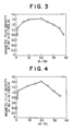
- Figures 3 and 4 indicate the relationship between silicon and aluminum content and magnetic flux density in a low magnetic field (80 A/m), in the case of (0.005 C - 0.08 Mn) steel.
- a high magnetic flux density was obtained with a silicon content in the range 0.1 - 3.5 percent, particularly in the range 0.6 - 2.5 percent, and an aluminum content in the range 0.1 - 3.0 percent, particularly in the range 0.9 - 2.5 percent.
- the present invention comprises the steps of: preparing a steel slab comprising, by weight, up to 0.01 percent carbon, 0.10 to 3.5 percent silicon, up to 0.20 percent manganese, up to 0.010 percent sulfur, up to 0.05 percent chromium, up to 0.01 percent molybdenum, up to 0.01 percent copper, 0.10 to 3.0 percent aluminum, up to 0.004 percent nitrogen, up to 0.005 percent oxygen and up to 0.0002 percent hydrogen, with the remainder being substantially iron; heating the slab to a temperature of 950 to 1300°C; hot-rolling the slab at least once at a rolling shape factor A of at least 0.6 at a finish rolling temperature of at least 800°C; dehydrogenation heat treatment at between 600 and 750°C for steel plate with a plate thickness of 50 mm or more; annealing at a temperature of 700 to 950°C, if required; annealing at a temperature of 750 to 950°C for hot-rolled steel plate with a plate thickness that is less than 50 mm;
- Carbon increases internal stresses in steel and is the element most responsible for degradation of magnetic properties, especially magnetic flux density in a low magnetic field, and as such, minimizing the carbon content helps to prevent a drop in the magnetic flux density in a low magnetic field. Also, lowering the carbon content decreases the magnetic aging of the steel, and thereby extends the length of time the steel retains its good magnetic properties. Hence, carbon is limited to a maximum of 0.010 percent. As shown in Figure 1, an even higher magnetic flux density can be obtained by reducing the carbon content to 0.005 percent or less.
- Silicon and aluminum are effective for achieving high magnetic flux density in a low magnetic field. With reference to Figure 3, therefore, 0.1 to 3.5 percent silicon is specified, more preferably 0.6 to 2.5 percent. With reference to Figure 4, 0.1 to 3.0 percent aluminum is specified, more preferably 0.9 to 2.5 percent.
- Low manganese is desirable for achieving high magnetic flux density in a low magnetic field and for reducing MnS inclusions. Therefore up to 0.20 percent is specified as the limit for manganese. To reduce MnS inclusions, a manganese content of no more than 0.10 percent is preferable.
- Chromium, molybdenum and copper each have an adverse effect on magnetic flux density in a low magnetic field, so the content amounts of these elements should be kept as low as possible. A further reason for minimizing these elements is to reduce the degree of segregation. Accordingly, an upper limit of 0.05 percent has been specified for chromium, 0.01 percent for molybdenum and 0.01 percent for copper.
- the method for producing the steel will now be described.
- the steel is heated to a temperature of at least 1150°C prior to rolling in order to coarsen the size of the austenite grains and improve the magnetic properties.
- An upper limit of 1300°C is specified to prevent scaling loss and to conserve on energy.
- finish rolling temperature is below 900°C, the rolling will refine the size of the crystal grains, adversely affecting the magnetic properties.
- a temperature of 900°C or more is specified with the aim of achieving an increase in the magnetic flux density as a result of a coarsening of the size of the crystal grains.
- the solidification process will always give rise to cavity defects, although the size of the defects may vary. Rolling has to be used to eliminate such cavity defects, so hot rolling has an important role.
- An effective means is to increase the amount of deformation per hot rolling, so that the deformation extends to the core of the steel plate.
- dehydrogenation heat treatment is employed on heavy plate with a plate thickness of 50 mm or more to coarsen the grain size and remove internal stresses. Hydrogen does not readily disperse in heavy plate having a thickness of 50 mm or more, which causes cavity defects and, in unison with the effect of the hydrogen itself, degrades magnetic flux density in a low magnetic field.
- dehydrogenation heat treatment is used.
- the temperature of the dehydrogenation heat treatment is below 600°C the dehydrogenation efficiency is lowered, while if the temperature exceeds 750°C there is a partial onset of transformation. Hence, a temperature range of 600 to 750°C is specified.
- Various studies relating to dehydrogenation time show a time of [0.6(t - 50) + 6] hours (t being plate thickness) to be suitable.
- the steel is annealed to coarsen the grain size and remove internal stresses. Annealing at a temperature below 750°C will not produce this coarsening of the crystal grains, while uniformity of the crystal grains through the thickness direction of the plate cannot be maintained if the temperature exceeds 950°C. Therefore an annealing temperature range of 750°C to 950°C has been specified.
- Normalizing is done to adjust the crystal grains in the thickness direction of the plate and to remove internal stresses. However, below 910°C, that is, an Ac3 point temperature, or over 1000°C, uniformity of the crystal grains in the thickness dimension of the plate cannot be maintained, so a range of 910 to 1000°C has been specified for the normalizing temperature.
- the dehydrogenation heat treatment employed for heavy plates having a plate thickness of 50 mm or more can also be used for the annealing or normalizing.
- Process B according to the present invention will next be described.
- the constituent components of the steel of Process B are the same as those of Process A.
- heating the plate at a relatively low temperature oriented the reheated ⁇ grains through the thickness direction, and the addition of light rolling at 800°C promoted grain growth.
- the result was that slightly coarse grains were obtained with a uniform size through the thickness direction.
- the crystalline texture introduced by the light rolling at or below 800°C orients the domains and facilitates the movement of domain walls, improving the magnetic properties.
- Figure 5 shows the relationship between the reduction ratio at up to 800°C and, respectively, magnetic flux density at 80 A/m, and variation of magnetic flux density through the thickness direction in (1.5 Si - 0.06 Mn - 1.2 Al) steel.
- a reduction ratio of 10 to 35 percent provides a high magnetic flux density that is uniform through the thickness direction.
- the steel is heated to a temperature of up to 1150°C prior to rolling. Exceeding this temperature will cause a large variation in the size of the reheated ⁇ grains through the thickness direction which will remain after completion of the rolling, producing non-uniformity of the grains.
- a heating temperature that is less than 950°C will increase the resistance to rolling deformation and the rolling load used to achieve a high rolling shape factor for eliminating cavity defects, as described below, hence the lower limit of 950°C.
- the solidification process will always gives rise to cavity defects, although the size of the defects may vary. Rolling has to be used to eliminate such cavity defects, so hot rolling has an important role.
- An effective means is to increase the amount of deformation per hot rolling at 800°C or above so that the deformation extends to the core of the steel plate.
- using high shape factor rolling which includes at least one pass at a rolling shape factor A of at least 0.6 so that the size of cavity defects is no larger than 100 micrometers is conducive to obtaining desirable magnetic properties. Eliminating cavity defects in the rolling process by using this high shape factor rolling markedly enhances dehydrogenation efficiency in the subsequent dehydrogenation heat treatment.
- the reason for using high shape factor rolling at a heating temperature of at least 800°C is that a temperature below 800°C will increase the resistance of the steel to rolling deformation and the load on the rolling mill.
- a reduction ratio of at least 10 percent at up to 800°C is required to achieve an increase in the magnetic flux density in a low magnetic field, hence a lower limit of 10 percent is specified.
- a reduction ratio of 35 percent at up to 800°C is specified as the upper limit since a reduction ratio over 35 percent will cause a large increase in the variation of the magnetic properties through the thickness direction.
- dehydrogenation heat treatment is employed on steel plate with a plate thickness of 50 mm or more to coarsen the grain size and remove internal stresses. Dehydrogenation heat treatment and normalizing, if required, are based on the procedures set out for Process A.
- component limits are used to impart uniform, high magnetic properties to heavy steel plate, enabling it to be applied to structures utilizing magnetic properties produced using DC magnetization.
- the production method uses component limits together with the adjustment of grain size after hot rolling and dehydrogenation heat treatment, making it a highly economical production method.
- Table 1 lists the production conditions, ferrite grain size and magnetic flux density in a low magnetic field.
- Steels 1 to 10 are inventive steels and steels 11 to 30 are comparative steels.
- Steels 1 to 5 which were finished to a thickness of 100 mm and had coarse, uniform grains, exhibited good magnetic properties. Compared with steel 1, steel 2, with lower carbon, steels 3 and 4, with lower manganese, and steel 5, with lower aluminum, showed better magnetic properties. Steels 6 to 8, which were finished to a thickness of 500 mm, steel 9, which was finished to a thickness of 40 mm, and steel 10, which was finished to a thickness of 20 mm, each had coarse, uniform grains and exhibited good magnetic properties.
- Table 2 lists the production conditions, ferrite grain size and magnetic flux density in a low magnetic field, and variation in magnetic flux density through the thickness direction.
- Steels 31 to 40 are inventive steels and steels 41 to 49 are comparative steels.
- Steels 31 to 35 were finished to a thickness of 100 mm and exhibited high magnetic flux density with low variation through the thickness direction. Compared with steel 31, steel 32, with lower carbon, steels 33 and 34, with lower manganese, and steel 35, with lower aluminum, showed better magnetic properties. Steels 36 to 38, which were finished to a thickness of 500 mm, steel 39, which was finished to a thickness of 40 mm, and steel 40, which was finished to a thickness of 6 mm, each exhibited high magnetic flux density with low variation through the thickness direction. Because the heating temperature used was too high, steel 41 showed a large variation in magnetic flux density through the thickness direction.
- Steel 42 showed low magnetic flux density, also with a large variation through the thickness direction, owing to a rolling finishing temperature that was too low, producing a small maximum rolling shape factor.
- Steel 43 showed low magnetic flux density as a result of a reduction ratio at up to 800°C that exceeded the lower limit, while steel 44 showed a large variation in magnetic flux density through the thickness direction as a result of a reduction ratio at up to 800°C that exceeded the upper limit.
- a low magnetic flux density and large variation in magnetic flux density through the thickness direction was produced in steel 45 because the maximum rolling shape factor was too low, in steel 46 because the dehydrogenation temperature was too low, in steel 47 because the annealing temperature was too low, in steel 48 because the normalizing temperature was too high and in steel 49 because it was not subjected to dehydrogenation heat treatment.
Landscapes
- Chemical & Material Sciences (AREA)
- Engineering & Computer Science (AREA)
- Physics & Mathematics (AREA)
- Metallurgy (AREA)
- Thermal Sciences (AREA)
- Crystallography & Structural Chemistry (AREA)
- Mechanical Engineering (AREA)
- Materials Engineering (AREA)
- Organic Chemistry (AREA)
- Manufacturing & Machinery (AREA)
- Electromagnetism (AREA)
- Manufacturing Of Steel Electrode Plates (AREA)
- Soft Magnetic Materials (AREA)
Applications Claiming Priority (4)
| Application Number | Priority Date | Filing Date | Title |
|---|---|---|---|
| JP212689/89 | 1989-08-18 | ||
| JP1212690A JPH0762175B2 (ja) | 1989-08-18 | 1989-08-18 | 板厚方向の磁気特性の均一な無方向性電磁厚板の製造方法 |
| JP1212689A JPH0762174B2 (ja) | 1989-08-18 | 1989-08-18 | 磁束密度の高い無方向性電磁厚板の製造方法 |
| JP212690/89 | 1989-08-18 |
Publications (2)
| Publication Number | Publication Date |
|---|---|
| EP0413306A1 true EP0413306A1 (fr) | 1991-02-20 |
| EP0413306B1 EP0413306B1 (fr) | 1996-04-10 |
Family
ID=26519363
Family Applications (1)
| Application Number | Title | Priority Date | Filing Date |
|---|---|---|---|
| EP90115574A Expired - Lifetime EP0413306B1 (fr) | 1989-08-18 | 1990-08-14 | Procédé de fabrication de tÔles en acier non-orientées ayant une densité de flux magnétique élevée |
Country Status (3)
| Country | Link |
|---|---|
| US (1) | US5062905A (fr) |
| EP (1) | EP0413306B1 (fr) |
| DE (1) | DE69026442T2 (fr) |
Cited By (3)
| Publication number | Priority date | Publication date | Assignee | Title |
|---|---|---|---|---|
| CN103436796A (zh) * | 2013-09-10 | 2013-12-11 | 武汉钢铁(集团)公司 | 一种变频压缩机用无取向电工钢及其生产方法 |
| CN104046760A (zh) * | 2014-06-19 | 2014-09-17 | 马钢(集团)控股有限公司 | 一种电工钢板的生产方法 |
| CN104438328A (zh) * | 2014-11-27 | 2015-03-25 | 武汉钢铁(集团)公司 | 一种提高无取向硅钢磁性能的热轧方法 |
Families Citing this family (12)
| Publication number | Priority date | Publication date | Assignee | Title |
|---|---|---|---|---|
| US5417739A (en) * | 1993-12-30 | 1995-05-23 | Ltv Steel Company, Inc. | Method of making high nitrogen content steel |
| EP0684320B1 (fr) * | 1994-04-26 | 2000-06-21 | LTV STEEL COMPANY, Inc. | Procédé pour la fabrication d'acier électrique |
| US6217673B1 (en) | 1994-04-26 | 2001-04-17 | Ltv Steel Company, Inc. | Process of making electrical steels |
| US5830259A (en) * | 1996-06-25 | 1998-11-03 | Ltv Steel Company, Inc. | Preventing skull accumulation on a steelmaking lance |
| US5885323A (en) * | 1997-04-25 | 1999-03-23 | Ltv Steel Company, Inc. | Foamy slag process using multi-circuit lance |
| US6068708A (en) * | 1998-03-10 | 2000-05-30 | Ltv Steel Company, Inc. | Process of making electrical steels having good cleanliness and magnetic properties |
| US7011139B2 (en) * | 2002-05-08 | 2006-03-14 | Schoen Jerry W | Method of continuous casting non-oriented electrical steel strip |
| EP1580289B1 (fr) * | 2002-12-05 | 2015-02-11 | JFE Steel Corporation | Tole d'acier magnetique non oriente et procede de production |
| US20050000596A1 (en) * | 2003-05-14 | 2005-01-06 | Ak Properties Inc. | Method for production of non-oriented electrical steel strip |
| JP5668767B2 (ja) | 2013-02-22 | 2015-02-12 | Jfeスチール株式会社 | 無方向性電磁鋼板製造用の熱延鋼板およびその製造方法 |
| CN103952629B (zh) * | 2014-05-13 | 2016-01-20 | 北京科技大学 | 一种中硅冷轧无取向硅钢及制造方法 |
| CN113174546B (zh) * | 2021-04-15 | 2022-06-14 | 鞍钢股份有限公司 | 一种解决取向硅钢热轧板晶粒粗大的方法 |
Citations (3)
| Publication number | Priority date | Publication date | Assignee | Title |
|---|---|---|---|---|
| AU505774B2 (en) * | 1977-09-09 | 1979-11-29 | Nippon Steel Corporation | A method for treating continuously cast steel slabs |
| EP0263413A2 (fr) * | 1986-09-29 | 1988-04-13 | Nippon Kokan Kabushiki Kaisha | Tôles magnétiques non orientées et fabrication de tôles magnétiques non orientées |
| EP0349853A2 (fr) * | 1988-06-24 | 1990-01-10 | Nippon Steel Corporation | Procédé de fabrication de tôles fortes en acier non-orientées ayant une densité de flux magnétique élevée |
-
1990
- 1990-08-14 EP EP90115574A patent/EP0413306B1/fr not_active Expired - Lifetime
- 1990-08-14 US US07/567,142 patent/US5062905A/en not_active Expired - Fee Related
- 1990-08-14 DE DE69026442T patent/DE69026442T2/de not_active Expired - Fee Related
Patent Citations (3)
| Publication number | Priority date | Publication date | Assignee | Title |
|---|---|---|---|---|
| AU505774B2 (en) * | 1977-09-09 | 1979-11-29 | Nippon Steel Corporation | A method for treating continuously cast steel slabs |
| EP0263413A2 (fr) * | 1986-09-29 | 1988-04-13 | Nippon Kokan Kabushiki Kaisha | Tôles magnétiques non orientées et fabrication de tôles magnétiques non orientées |
| EP0349853A2 (fr) * | 1988-06-24 | 1990-01-10 | Nippon Steel Corporation | Procédé de fabrication de tôles fortes en acier non-orientées ayant une densité de flux magnétique élevée |
Non-Patent Citations (5)
| Title |
|---|
| PATENT ABSTRACTS OF JAPAN, vol. 10, no. 71 (C-334)[2128], 20th March 1986; & JP-A-60 208 417 (SUMITOMO) 21-10-1985 * |
| PATENT ABSTRACTS OF JAPAN, vol. 10, no. 71 (C-334)[2128], 20th march 1986; & JP-A-60 208 418 (SUMITOMO) 21-10-1985 * |
| PATENT ABSTRACTS OF JAPAN, vol. 13, no. 399 (C-632)[3747], 5th September 1989; & JP-A-1 142 028 (KAWASAKI STEEL) 02-06-1989 * |
| PATENT ABSTRACTS OF JAPAN, vol. 2, no. 46 (C-009), 28th March 1978; & JP-A-53 2332 (SHIN NIPPON SEITETSU) 01-11-1978 * |
| PATENT ABSTRACTS OF JAPAN, vol. 9, no. 237 (C-305)[1960], 24th September 1985; & JP-A-60 96 749 (SHIN NIPPON SEITETSU) 30-05-1985 * |
Cited By (4)
| Publication number | Priority date | Publication date | Assignee | Title |
|---|---|---|---|---|
| CN103436796A (zh) * | 2013-09-10 | 2013-12-11 | 武汉钢铁(集团)公司 | 一种变频压缩机用无取向电工钢及其生产方法 |
| CN103436796B (zh) * | 2013-09-10 | 2015-10-14 | 武汉钢铁(集团)公司 | 一种变频压缩机用无取向电工钢及其生产方法 |
| CN104046760A (zh) * | 2014-06-19 | 2014-09-17 | 马钢(集团)控股有限公司 | 一种电工钢板的生产方法 |
| CN104438328A (zh) * | 2014-11-27 | 2015-03-25 | 武汉钢铁(集团)公司 | 一种提高无取向硅钢磁性能的热轧方法 |
Also Published As
| Publication number | Publication date |
|---|---|
| EP0413306B1 (fr) | 1996-04-10 |
| DE69026442T2 (de) | 1996-11-28 |
| DE69026442D1 (de) | 1996-05-15 |
| US5062905A (en) | 1991-11-05 |
Similar Documents
| Publication | Publication Date | Title |
|---|---|---|
| KR100266552B1 (ko) | 자속밀도가 높으면서 철손이 낮은 일방향성 전자강판 및 그 제조방법 | |
| EP0413306B1 (fr) | Procédé de fabrication de tÔles en acier non-orientées ayant une densité de flux magnétique élevée | |
| KR20200076831A (ko) | 무방향성 전기강판 및 그 제조방법 | |
| EP0388776B1 (fr) | Procédé de fabrication de tôles d'acier magnétique non orientées, à densité de flux magnétique élevée et ayant des propriétés magnétiques uniformes dans le sens de l'épaisseur | |
| KR930005890B1 (ko) | 판후정도 및 자기특성이 극히 균일한 무방향성 전기강판의 제조방법 | |
| KR100345706B1 (ko) | 자기적특성이우수한무방향성전기강판및그제조방법 | |
| EP0349853B1 (fr) | Procédé de fabrication de tôles fortes en acier non-orientées ayant une densité de flux magnétique élevée | |
| EP0084569A1 (fr) | Procede de fabrication de plaque d'acier electromagnetique isotrope possedant d'excellentes caracteristiques magnetiques | |
| EP0588342B1 (fr) | Tôle d'acier électrique à grains orientés et matériau à haute densité de flux magnétique et procédé pour leur fabrication | |
| EP0315948A2 (fr) | Procédé pour la fabrication de tôles minces d'acier électrique à grains orientés, à faibles pertes dans le fer et à densité de flux élevée | |
| KR930002533B1 (ko) | 자기 시일드용 전자 강판 및 그 제조방법 | |
| KR20220089076A (ko) | 무방향성 전기강판 및 그 제조방법 | |
| JP3357602B2 (ja) | 磁気特性に優れる方向性電磁鋼板の製造方法 | |
| KR20240147141A (ko) | 무방향성 전기강판 및 이의 제조방법 | |
| KR100240993B1 (ko) | 철손이 낮은 무방향성 전기강판 및 그 제조방법 | |
| JPH0814015B2 (ja) | 磁気特性および表面性状の優れた無方向性電磁鋼板およびその製造方法 | |
| JPH0797628A (ja) | 磁束密度が高く、鉄損の低い無方向性電磁鋼板の製造方法 | |
| KR930011407B1 (ko) | 자속밀도와 투자율이 높은 무방향성 전기강판 및 그 제조방법 | |
| KR20000031656A (ko) | 자기특성이 우수하고 자기이방성이 작은 무방향성 전기강판의제조방법 | |
| JPH02243719A (ja) | 切削性が良く板厚方向の磁気特性の均一な良電磁厚板の製造方法 | |
| CN1107734C (zh) | 具有高磁导率的非取向电磁钢板及其制造方法 | |
| JP2000017330A (ja) | 鉄損の低い無方向性電磁鋼板の製造方法 | |
| JP3474741B2 (ja) | 磁気特性に優れた方向性電磁鋼板の製造方法 | |
| JPH06104866B2 (ja) | 直流磁化用電磁厚板の製造方法 | |
| JP2560090B2 (ja) | 無方向性電磁鋼板の製造方法 |
Legal Events
| Date | Code | Title | Description |
|---|---|---|---|
| PUAI | Public reference made under article 153(3) epc to a published international application that has entered the european phase |
Free format text: ORIGINAL CODE: 0009012 |
|
| AK | Designated contracting states |
Kind code of ref document: A1 Designated state(s): DE FR GB |
|
| 17P | Request for examination filed |
Effective date: 19901228 |
|
| 17Q | First examination report despatched |
Effective date: 19930722 |
|
| GRAA | (expected) grant |
Free format text: ORIGINAL CODE: 0009210 |
|
| AK | Designated contracting states |
Kind code of ref document: B1 Designated state(s): DE FR GB |
|
| REF | Corresponds to: |
Ref document number: 69026442 Country of ref document: DE Date of ref document: 19960515 |
|
| ET | Fr: translation filed | ||
| GRAH | Despatch of communication of intention to grant a patent |
Free format text: ORIGINAL CODE: EPIDOS IGRA |
|
| PLBE | No opposition filed within time limit |
Free format text: ORIGINAL CODE: 0009261 |
|
| STAA | Information on the status of an ep patent application or granted ep patent |
Free format text: STATUS: NO OPPOSITION FILED WITHIN TIME LIMIT |
|
| 26N | No opposition filed | ||
| PGFP | Annual fee paid to national office [announced via postgrant information from national office to epo] |
Ref country code: GB Payment date: 19970805 Year of fee payment: 8 |
|
| PGFP | Annual fee paid to national office [announced via postgrant information from national office to epo] |
Ref country code: FR Payment date: 19970811 Year of fee payment: 8 |
|
| PGFP | Annual fee paid to national office [announced via postgrant information from national office to epo] |
Ref country code: DE Payment date: 19970822 Year of fee payment: 8 |
|
| PG25 | Lapsed in a contracting state [announced via postgrant information from national office to epo] |
Ref country code: GB Free format text: LAPSE BECAUSE OF NON-PAYMENT OF DUE FEES Effective date: 19980814 |
|
| GBPC | Gb: european patent ceased through non-payment of renewal fee |
Effective date: 19980814 |
|
| PG25 | Lapsed in a contracting state [announced via postgrant information from national office to epo] |
Ref country code: FR Free format text: LAPSE BECAUSE OF NON-PAYMENT OF DUE FEES Effective date: 19990430 |
|
| PG25 | Lapsed in a contracting state [announced via postgrant information from national office to epo] |
Ref country code: DE Free format text: LAPSE BECAUSE OF NON-PAYMENT OF DUE FEES Effective date: 19990601 |
|
| REG | Reference to a national code |
Ref country code: FR Ref legal event code: ST |