EP0413337B2 - Véhicule ferroviaire avec moteur électrique à entraínement direct - Google Patents
Véhicule ferroviaire avec moteur électrique à entraínement direct Download PDFInfo
- Publication number
- EP0413337B2 EP0413337B2 EP90115713A EP90115713A EP0413337B2 EP 0413337 B2 EP0413337 B2 EP 0413337B2 EP 90115713 A EP90115713 A EP 90115713A EP 90115713 A EP90115713 A EP 90115713A EP 0413337 B2 EP0413337 B2 EP 0413337B2
- Authority
- EP
- European Patent Office
- Prior art keywords
- wheel
- rotor
- electric motor
- drive according
- driven
- Prior art date
- Legal status (The legal status is an assumption and is not a legal conclusion. Google has not performed a legal analysis and makes no representation as to the accuracy of the status listed.)
- Expired - Lifetime
Links
- 238000013016 damping Methods 0.000 claims description 7
- 230000004907 flux Effects 0.000 claims description 7
- 230000005291 magnetic effect Effects 0.000 claims description 7
- 239000003302 ferromagnetic material Substances 0.000 claims description 5
- 239000000463 material Substances 0.000 claims description 5
- 239000010941 cobalt Substances 0.000 claims description 2
- 229910017052 cobalt Inorganic materials 0.000 claims description 2
- XEEYBQQBJWHFJM-UHFFFAOYSA-N Iron Chemical compound [Fe] XEEYBQQBJWHFJM-UHFFFAOYSA-N 0.000 claims 2
- 229910052779 Neodymium Inorganic materials 0.000 claims 1
- GUTLYIVDDKVIGB-UHFFFAOYSA-N cobalt atom Chemical compound [Co] GUTLYIVDDKVIGB-UHFFFAOYSA-N 0.000 claims 1
- 229910052742 iron Inorganic materials 0.000 claims 1
- QEFYFXOXNSNQGX-UHFFFAOYSA-N neodymium atom Chemical compound [Nd] QEFYFXOXNSNQGX-UHFFFAOYSA-N 0.000 claims 1
- 239000000725 suspension Substances 0.000 description 11
- 230000005540 biological transmission Effects 0.000 description 5
- 230000008901 benefit Effects 0.000 description 4
- 238000009434 installation Methods 0.000 description 4
- 238000001816 cooling Methods 0.000 description 3
- 230000035939 shock Effects 0.000 description 3
- 238000004804 winding Methods 0.000 description 3
- 230000000694 effects Effects 0.000 description 2
- 230000002349 favourable effect Effects 0.000 description 2
- 229910052761 rare earth metal Inorganic materials 0.000 description 2
- 229910052772 Samarium Inorganic materials 0.000 description 1
- 230000001133 acceleration Effects 0.000 description 1
- 230000037007 arousal Effects 0.000 description 1
- 230000000052 comparative effect Effects 0.000 description 1
- 230000008878 coupling Effects 0.000 description 1
- 238000010168 coupling process Methods 0.000 description 1
- 238000005859 coupling reaction Methods 0.000 description 1
- 230000005611 electricity Effects 0.000 description 1
- 230000005284 excitation Effects 0.000 description 1
- ZWKKPKNPCSTXGA-UHFFFAOYSA-N iron neodymium Chemical compound [Fe].[Fe].[Nd] ZWKKPKNPCSTXGA-UHFFFAOYSA-N 0.000 description 1
- 150000002910 rare earth metals Chemical class 0.000 description 1
- KZUNJOHGWZRPMI-UHFFFAOYSA-N samarium atom Chemical compound [Sm] KZUNJOHGWZRPMI-UHFFFAOYSA-N 0.000 description 1
Images

Classifications
-
- B—PERFORMING OPERATIONS; TRANSPORTING
- B61—RAILWAYS
- B61C—LOCOMOTIVES; MOTOR RAILCARS
- B61C9/00—Locomotives or motor railcars characterised by the type of transmission system used; Transmission systems specially adapted for locomotives or motor railcars
- B61C9/38—Transmission systems in or for locomotives or motor railcars with electric motor propulsion
- B61C9/48—Transmission systems in or for locomotives or motor railcars with electric motor propulsion with motors supported on vehicle frames and driving axles, e.g. axle or nose suspension
-
- B—PERFORMING OPERATIONS; TRANSPORTING
- B61—RAILWAYS
- B61F—RAIL VEHICLE SUSPENSIONS, e.g. UNDERFRAMES, BOGIES OR ARRANGEMENTS OF WHEEL AXLES; RAIL VEHICLES FOR USE ON TRACKS OF DIFFERENT WIDTH; PREVENTING DERAILING OF RAIL VEHICLES; WHEEL GUARDS, OBSTRUCTION REMOVERS OR THE LIKE FOR RAIL VEHICLES
- B61F3/00—Types of bogies
- B61F3/02—Types of bogies with more than one axle
- B61F3/04—Types of bogies with more than one axle with driven axles or wheels
-
- B—PERFORMING OPERATIONS; TRANSPORTING
- B61—RAILWAYS
- B61F—RAIL VEHICLE SUSPENSIONS, e.g. UNDERFRAMES, BOGIES OR ARRANGEMENTS OF WHEEL AXLES; RAIL VEHICLES FOR USE ON TRACKS OF DIFFERENT WIDTH; PREVENTING DERAILING OF RAIL VEHICLES; WHEEL GUARDS, OBSTRUCTION REMOVERS OR THE LIKE FOR RAIL VEHICLES
- B61F3/00—Types of bogies
- B61F3/16—Types of bogies with a separate axle for each wheel
Definitions
- the invention relates to an electric motor direct drive for Vehicle wheels the preamble of claim 1.
- a direct drive is known from DE-A-38 17 537.
- Direct drive is usually understood and in the present application such drives in which the electric motor a wheel to be driven without the interposition of a transmission is spatially closely assigned.
- the torque transmission connection of the Rotor of the electric motor to the wheel to be driven is in the invention either on the wheel to be driven itself or on an axle shaft made on which the wheel to be driven rotates.
- Electromotive direct drives are sometimes also used as axis motors designated.
- the invention is based, a comparative task light and space-saving direct drive available however - measured by the required installation volume and weight provides comparatively high torque.
- the magnetic flux density at the air gap-side pole faces of the rotor is larger than at the end faces the permanent magnet.
- Electronically commutated electric motors are known per se, so that no further details are described in this regard have to.
- Electronically commutated electric motors can be used by the Compare the design system most closely with DC motors.
- a rotation position sensor often one Hall sensor, which detects the current rotational position of the rotor and is based on signals from the rotation position sensor Stator windings or stator coils with correct timing and correct sign electrical voltage applied.
- the direct drive according to the invention is particularly preferred for High-speed rail vehicles because these are high Wheel speeds occur, that is, given the torque of the Drive motor high drive powers become available, and because at this is the aspect of a large acceleration ability is not in the foreground.
- high-speed rail vehicles are considered those that Top speed in the range of 200 to 300 km / h, or too about that.
- the rotor weight is low, as measured by the torque of the engine according to the invention is achievable, advantageous because the rotor of the motor in many cases belongs to the unsprung vehicle masses.
- the rotor is preferably equipped with highly coercive permanent magnets or Permanent magnets built with a high energy product.
- Permanent magnets are known, especially from rare earth-cobalt material or iron neodymium material.
- the rare earth material part can consist of one or more rare earth elements, in particular Samarium.
- Highly coercive permanent magnets or permanent magnets with high energy product deliver high permanent magnet excitation, allow a high motor EMF with comparatively low Inductance, allow a particularly compact structure of the rotor, and allow the engine to be constructed with a comparatively large, radial air gap width, which is mentioned from below Reasons is favorable.
- connection device it is possible and preferred to use a rotor Connection device to connect to the wheel, the small one Allows relative movements between the wheel and the rotor, especially in the direction perpendicular to the axis of rotation of the wheel or the rotor, especially in the vertical direction.
- the Connection device can be a type of flexible coupling.
- the connecting device is preferably resilient and / or dampening. The main advantage of the connection device mentioned is that Keep the shock maxima of the wheel away from the rotor. This applies itself then when the rotor by means of the bearing of the wheel or the Axle shaft of the wheel is mounted.
- the rotor is supported by its own bearing, whereby a wheel primary suspension without rotor primary suspension and a stronger one Decoupling the wheel joints from the rotor are possible. Furthermore, the Variant possible that the entire electric motor, i.e. stator and rotor, is supported and / or damped supported on the vehicle, wherein for example the wheels, their axles or axle shafts and their Electric motors the unsprung vehicle masses turn off.
- the wheel to be driven with the interposition of a Arranged as early as possible in the shock transmission chain Primary suspension is connected to the vehicle.
- the "earliest" or closest to the bike The location of the primary suspension is a primary suspension between the actual wheel and its stationary wheel axis or its co-rotating axle shaft.
- the "two earliest” or the second closest location of the primary suspension to the wheel is between the stationary wheel axle or the rotating axle shaft and the vehicle. It it is pointed out that in both cases the rotor of the electric motor either to that through the primary suspension unsprung mass (wheel or wheel axle or Axle shaft) may belong to or through the primary suspension sprung mass in the shock transmission chain behind the primary suspension.
- the wheel to be driven can at least on one axial side a brake disc can be rigidly assigned.
- On the axial side opposite the electric motor is normally sufficient for such a brake disc Place.
- this brake disc can between the electric motor and the wheel to be driven a brake disk rigidly assigned to the wheel is provided his.
- the rotor of the electric motor has a brake disc rigidly assignable. This often offers spatial Benefits.
- the brake disc the sprung mass downstream of the primary suspension be assigned.
- the electric motor provided according to the invention is measured on its torque - so small that it often arranged on the outside of the wheel to be driven can be, especially still within that for railway vehicles prescribed vehicle limit.
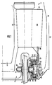
- a rail vehicle 2 for example a motor car for passenger transport, whereby a rail wheel 4 to be driven on one side of the vehicle, whose axle motor 6, part of the wheel 4 and the motor 6 supporting chassis 8 of the vehicle 2, and a lower part of the vehicle body or the vehicle body 10 for receiving the payload or the people to be transported.
- the chassis For example, 8 can be one of two bogies be on which the vehicle body 10 rests. It can but also act as a chassis 8, which is non-rotatable is connected to the vehicle body 10. Between the wheel 4 and the chassis 8 and / or between the Chassis 8 and the vehicle body 10 can not Drawn in suspension and possibly damping be provided.
- the wheel 4 is rigidly attached to an axle shaft 12. Axial left and right of the wheel is one Brake disc 14 rigidly attached to the axle shaft 12. The axle shaft 12 is rotatable in the bearing 16 Chassis 8 stored.
- the axle shaft 12 is on the right side in FIG. 1 extended and with a flange-like end region 18 larger diameter.
- end region 18 1 is essentially open to the right in FIG cup-shaped outer rotor 20 of the axis motor 8 connected, with the interposition of a springy one compliant, damping connecting ring 22, for example made of suitable rubber or plastic.
- the connecting ring 22 sits on the axial side facing the wheel of the end region 18, and the end wall of the rotor 20 there projects radially inwards to the connecting ring 22.
- the axle motor 6 is seated to the right of the wheel in FIG. 1, So outside of the vehicle from the wheel 4.
- the chassis 8 points to the right of the rotor in FIG. 1 20 an extension 24 projecting downwards.
- the inside of this extension 24 is circular Mounting flange 26 attached.
- the mounting flange 26 wears an inwardly projecting, strong, tubular support 28.
- On the outer circumference of support 28 are annularly distributed stator poles 30 made of ferromagnetic Material with windings 32 attached.
- the Rotor 20 has permanent magnets distributed in a ring, 1 in order to increase clarity are drawn.
- the pole pitch of the permanent magnets is matched to the pole pitch of the stator poles 30, so that through the stator constructed with the stator poles 30 and those attached to the rotor 20 Permanent magnets an electric motor with permanent magnetic Arousal is formed.
- the permanent magnets are along of the rotor circumference alternating polarity.
- a support column 34 can be seen above the wheel 4 1 is the right side of the support column 34 an installation space for the actuator of the motor 6, the Control electronics of engine 6 and for engine 6 assigned cooling unit.
- the actuators of the engine 6 are by means of a rotational position sensor, not shown of the motor 6 controlled so that it the individual windings 32 of the stator poles 30 electrical Supply electricity in the correct time and with the correct sign.
- From the installation space 36 to the extension 24 and through the Extension 24 leads into the interior of the support 28 a channel 38 in which power cables and cooling lines run.
- Line 39 indicates the outer contour of the vehicle, for example with the German Federal Railways Is 2950 mm wide.
- Line 40 is the narrowest permitted Route limitation indicated, that is Limit up to the outer parts of the track, such as tunnel walls, Masts and the like, as close as possible to the rails of the driveway may be arranged. It deals the so-called vehicle limitation, for example II of the railway operating regulations of the Deutsche Bundesbahn. It can be seen that the axis motor 6 within the vehicle contour 39 and within the boundary 40 located.
- At 42 is the so-called lemniscate handlebar indicated for drive setting.
- the drawing has to be added in mirror image on the left, supplemented by a middle part of the vehicle and one introduce the upper vehicle area to the whole Cross-section of vehicle 2 in front of you.
- a cooling air outlet At the upper end of the installation space 36 is a cooling air outlet at 44 indicated.
- the vehicle body 10 is sufficient as a low-floor vehicle deeper than the top of the perimeter of the Rads 4 corresponds.
- the corresponding wheel 4 on the other side of the vehicle is also with an axle motor 6 provided.
- Axle shaft 12 to the opposite wheel 4 to perform and both wheels 4 by a common axle motor 6 to drive is also possible.
- the rotor 20 could also be connected, for example, by bolts directly with the wheel 4 or the right brake disc 14 be connected.
- the wheel 4 on the Axis 12 can be rotatably mounted.
- the right support of the Axis 12 would then, for example, on the extension 24 of the Chassis 8 take place.
- the springy, flexible and damping connecting ring 22 leads to impacts, in particular impact maxima, be passed on reduced to the rotor 20.
- FIG. 3 shows a variant in which the rotor 20 is supported in the support 28. Between the rotor 20 and the end region 18 of the axle shaft 12 is in turn one resilient and damping connecting ring 22 arranged. In this version, impacts of wheel 4 still occur much reduced to the rotor 20. Also in this case the freedom, the wheel 4 or the Axle shaft 12 with a larger yield path and / or damped support because the connecting ring 22 the Yield path. If the rotor 20 has its own Storage 17, for example according to FIG. 3, can for example in a manner not shown suitable fasteners, the small relative movements allow and if necessary springy and / or have a dampening effect, directly with bike 4 or the right one Brake disc 14 may be connected. Alternatively, the rotor 20 be rotatably mounted on the right on the extension 24.
- the end wall 48 of the rotor 20 can not be shown in FIG Way radially enlarged to be there Train the braking area.
- Fig. 2 is a preferred embodiment of the rotor 20 shown in magnetic terms.
- the permanent magnets 50 shown have end faces 52 on which the magnetic flux in subsequent ferromagnetic material 54 passes and the - rough spoken - point in the circumferential direction of the rotor 20.
- the ferromagnetic material areas 54 each arranged between two with opposite polarity Permanent magnets 50 form radially inwards Pole faces 56.
- Each pole face 56 has a smaller one Magnetic flux exit area than it is the sum of the Magnetic flux transfer surfaces 52 of the two subsequent ones Permanent magnets 50, each measured in a radial plane, corresponds, so that there is a flux concentration effect results.
Landscapes
- Engineering & Computer Science (AREA)
- Mechanical Engineering (AREA)
- Chemical & Material Sciences (AREA)
- Combustion & Propulsion (AREA)
- Transportation (AREA)
- Arrangement Or Mounting Of Propulsion Units For Vehicles (AREA)
- Connection Of Motors, Electrical Generators, Mechanical Devices, And The Like (AREA)
- Electric Propulsion And Braking For Vehicles (AREA)
- Power Steering Mechanism (AREA)
- Automatic Cycles, And Cycles In General (AREA)
Claims (11)
- Moteur électrique à entraínement direct pour roues de véhicules, notamment roues de véhicules ferroviaire, présentant les caractéristiques suivantes :a) un moteur électrique (6) est monté axialement contre la roue à entraíner (4) pour la transmission du moment de rotation, les axes de rotation du rotor (20) et de la roue à entraíner (4) étant au moins sensiblement en alignement mutuel;b) le rotor (20) est constitué sous forme d'un rotor externe du moteur électrique sans boítier (6); etc) le stator (30) du moteur électrique (6) est monté de façon fixe en rotation sur le côté qui est à l'opposé de la roue entraínée (4);
caractérisé en ce que
le rotor du moteur électrique (6) à commutation électronique comprend, répartis en alternance, des aimants permanents (50) ainsi que des régions de matière ferromagnétique (54), et est constitué, du point de vue de la concentration du flux, avec une densité de flux magnétique sur les surfaces polaires (56) du rotor (20) situées côté entrefer plus élevée que sur les surfaces d'extrémité (52) des aimants permanents (50), les aimants permanents (50) étant, en section droite, de plus en plus étroits de l'extérieur vers l'intérieur et les régions (54) de matériau ferromagnétique de plus en plus larges de l'extérieur vers l'intérieur. - Etraínement selon la revendication 1, caractérisé en ce que le rotor (20) est monté au moyen du palier (16) de la roue (4).
- Etraínement selon la revendication 1 ou 2, caractérisé en ce que sont prévus des aimants permanents fortement coercitifs (50), de préférence constitués en terre rare-cobalt ou en fer néodyme.
- Entraínement selon l'une quelconque des revendications 1 à 3, caractérisé en ce que le rotor (20) est raccordé par un dispositif de liaison (22) à la roue (4), qui admet de petits mouvements relatifs entre la roue (4) et le rotor (20).
- Entraínement selon la revendication 4, caractérisé en ce que le dispositif de liaison (22) est élastiquement flexible.
- Entraínement selon la revendication 4 ou 5, caractérisé en ce que le dispositif de liaison (22) est à effet amortisseur.
- Entraínement selon l'une quelconque des revendications 1 à 6, caractérisé en ce que l'arbre d'essieu (12) est supporté élastiquement sur le véhicule (4)
- Entraínement selon l'une quelconque des revendications 1 à 7, caractérisé en ce que la roue est supportée élastiquement sur l'essieu de roue (12).
- Entraínement selon l'une quelconque des revendications 1 à 8, caractérisé en ce qu'un disque de frein (14) est associé rigidement au moteur (20).
- Entraínement selon l'une quelconque des revendications 1 à 9, caractérisé en ce que le moteur électrique (6) est monté sur le côté externe de la roue (4).
- Entraínement selon la revendication 10, caractérisé en ce que l'entraínement est monté à l'intérieur des limites (28) prescrites pour les véhicules ferroviaires.
Applications Claiming Priority (2)
| Application Number | Priority Date | Filing Date | Title |
|---|---|---|---|
| DE3927311A DE3927311A1 (de) | 1989-08-18 | 1989-08-18 | Elektromotorischer schienenfahrzeug-direktantrieb |
| DE3927311 | 1989-08-18 |
Publications (3)
| Publication Number | Publication Date |
|---|---|
| EP0413337A1 EP0413337A1 (fr) | 1991-02-20 |
| EP0413337B1 EP0413337B1 (fr) | 1994-06-08 |
| EP0413337B2 true EP0413337B2 (fr) | 2000-02-09 |
Family
ID=6387376
Family Applications (1)
| Application Number | Title | Priority Date | Filing Date |
|---|---|---|---|
| EP90115713A Expired - Lifetime EP0413337B2 (fr) | 1989-08-18 | 1990-08-16 | Véhicule ferroviaire avec moteur électrique à entraínement direct |
Country Status (3)
| Country | Link |
|---|---|
| EP (1) | EP0413337B2 (fr) |
| AT (1) | ATE106807T1 (fr) |
| DE (2) | DE3927311A1 (fr) |
Cited By (1)
| Publication number | Priority date | Publication date | Assignee | Title |
|---|---|---|---|---|
| CN105083297A (zh) * | 2015-09-14 | 2015-11-25 | 南车资阳机车有限公司 | 采用直接驱动电机的超窄轨铁路机车车辆轮对 |
Families Citing this family (26)
| Publication number | Priority date | Publication date | Assignee | Title |
|---|---|---|---|---|
| IT219394Z2 (it) * | 1990-03-13 | 1993-02-26 | Carrello motorizzato a ruote indipendenti per veicoli a pianale ribassato | |
| DE4234831C1 (de) * | 1992-10-15 | 1994-01-05 | Siemens Ag | Antrieb für ein Fahrzeugrad |
| EP0567445B1 (fr) * | 1992-04-22 | 1996-01-10 | SGP Verkehrstechnik Gesellschaft m.b.H. | Train de roulement pour véhicules ferroviaires, notamment pour véhicules ferroviaires à plate-forme surbaissée |
| DE4223633A1 (de) * | 1992-07-17 | 1994-01-20 | Siemens Ag | Antriebsmotor |
| AT401761B (de) * | 1992-08-05 | 1996-11-25 | Abb Daimler Benz Transp | Getriebeloser radnabenmotor für ein rad eines schienenfahrzeuges |
| DE4302042C2 (de) * | 1993-01-26 | 2000-06-08 | Hs Tech & Design | Elektromotor |
| DE4303069C1 (de) * | 1993-02-03 | 1994-03-17 | Siemens Ag | Elektromotorischer Direktantrieb |
| DE19522382C1 (de) * | 1995-06-23 | 1996-12-19 | Voith Gmbh J M | Transversalflußmaschine zum Einsatz in einem Direktantrieb für Fahrzeuge, insbesondere Bahnantrieb |
| DE19600420C1 (de) * | 1996-01-08 | 1997-02-27 | Siemens Ag | Einzelradantrieb für ein elektrisch angetriebenes Fahrzeug |
| DE29601339U1 (de) * | 1996-01-26 | 1996-04-11 | Böttcher, Manfred, 22397 Hamburg | Laufradblock |
| DE19653251A1 (de) * | 1996-12-20 | 1998-06-25 | Juergen Dr Wolf | Luftgummireifen-gefedertes Schienenrad |
| DE19704392A1 (de) * | 1997-02-06 | 1998-08-13 | Voith Turbo Kg | Verwendung einer Transversalflußmaschine zum Einsatz in einem Einzelradantrieb für Fahrzeuge und Einzelradantrieb für Fahrzeuge |
| AT405390B (de) | 1997-03-19 | 1999-07-26 | Abb Daimler Benz Transp | Elektromotorischer radnabenantrieb für ein fahrzeugrad |
| DE19714789B4 (de) * | 1997-04-10 | 2010-08-12 | Dwa Deutsche Waggonbau Gmbh | Antriebsgestaltung in Triebfahrzeugen für Niederflurfahrzeuge, insbesondere für Straßenbahnen im innerstädtischen Nahverkehr |
| DE19723781A1 (de) * | 1997-06-06 | 1998-12-10 | Abb Daimler Benz Transp | Stromrichtergespeistes Antriebssystem |
| DE10047911A1 (de) | 2000-09-27 | 2002-04-18 | Siemens Ag | Antrieb eines Radsatzes |
| JP3879413B2 (ja) | 2001-02-28 | 2007-02-14 | 株式会社日立製作所 | 搬送システム及び回転電機 |
| JP4311139B2 (ja) * | 2003-09-12 | 2009-08-12 | トヨタ自動車株式会社 | 車輪構造 |
| EP1884433A1 (fr) * | 2006-08-03 | 2008-02-06 | ANSALDOBREDA S.p.A. | Bogie motorisé à roues indépendantes pour un tramway à plancher surbaissé |
| CZ2007371A3 (cs) * | 2007-05-29 | 2009-02-18 | ŠKODA TRANSPORTATION s. r. o. | Pohon kola vozidla, zejména kolejového |
| DE102009051773B4 (de) * | 2009-11-04 | 2015-09-03 | Michael Reutter | Neugestaltung einer Eisenbahnachse ohne Antrieb |
| HUP1100344A2 (en) | 2011-06-28 | 2012-12-28 | Gyula Istvan Gyoeker | Wheel body motor for railway |
| DE102013000852B4 (de) * | 2013-01-21 | 2023-02-23 | Sew-Eurodrive Gmbh & Co Kg | Schienentransportsystem und Verfahren zum Betreiben eines Schienentransportsystems |
| DE102013014781A1 (de) | 2013-09-09 | 2015-03-12 | PINTSCH TIEFENBACH GmbH | Schienengebundener Förderwagen |
| CZ2015583A3 (cs) * | 2015-08-28 | 2017-06-28 | Ĺ KODA TRANSPORTATION a.s. | Pohon otočného podvozku, zejména pro nízkopodlažní kolejové vozidlo |
| AT525479A1 (de) | 2021-09-30 | 2023-04-15 | Siemens Mobility Austria Gmbh | Fahrwerk für ein Schienenfahrzeug und Schienenfahrzeug |
Family Cites Families (15)
| Publication number | Priority date | Publication date | Assignee | Title |
|---|---|---|---|---|
| DE213482C (fr) * | ||||
| DE130694C (fr) * | ||||
| DE319658C (de) * | 1920-03-27 | Reinhold Preuss | In einem Fahrzeugrade eingebauter Elektromotor | |
| DE189934C (fr) * | 1906-10-25 | |||
| GB1135764A (en) * | 1965-02-25 | 1968-12-04 | Westinghouse Brake & Signal | A dynamo electric machine for drive and/or braking purposes |
| GB1231782A (fr) * | 1967-05-08 | 1971-05-12 | ||
| US3479967A (en) * | 1967-08-25 | 1969-11-25 | George Crompton | Electric locomotive |
| FR2068109A5 (fr) * | 1969-11-28 | 1971-08-20 | Guimbal Jean | |
| DE2316932A1 (de) * | 1973-04-04 | 1974-10-17 | Hurth Masch Zahnrad Carl | Einrichtung fuer ein antriebsrad von kraftfahrzeugen |
| DE2357451C2 (de) * | 1973-11-17 | 1981-09-24 | Carl Hurth Maschinen- und Zahnradfabrik GmbH & Co, 8000 München | Radnabenantrieb mit Bremse |
| BE809690A (fr) * | 1974-01-14 | 1974-07-15 | Acec | Bogie a roues elastiques a grande vitesse. |
| ZA754983B (en) * | 1974-08-12 | 1976-07-28 | British Railways Board | Improvements relating to vehicle drive arrangenents using electric motors |
| DE3245033C2 (de) * | 1981-12-05 | 2003-05-28 | Papst Licensing Gmbh & Co Kg | Kollektorloser Gleichstrommotor |
| DE3345260C2 (de) * | 1983-12-14 | 1996-04-11 | Magnet Motor Gmbh | Elektrisches Schienenfahrzeug |
| DE3817537A1 (de) * | 1988-05-24 | 1988-12-22 | Josef Klaus | Antrieb fuer ein fahrzeug |
-
1989
- 1989-08-18 DE DE3927311A patent/DE3927311A1/de not_active Withdrawn
-
1990
- 1990-08-16 EP EP90115713A patent/EP0413337B2/fr not_active Expired - Lifetime
- 1990-08-16 AT AT90115713T patent/ATE106807T1/de not_active IP Right Cessation
- 1990-08-16 DE DE59006009T patent/DE59006009D1/de not_active Expired - Fee Related
Cited By (1)
| Publication number | Priority date | Publication date | Assignee | Title |
|---|---|---|---|---|
| CN105083297A (zh) * | 2015-09-14 | 2015-11-25 | 南车资阳机车有限公司 | 采用直接驱动电机的超窄轨铁路机车车辆轮对 |
Also Published As
| Publication number | Publication date |
|---|---|
| EP0413337B1 (fr) | 1994-06-08 |
| DE59006009D1 (de) | 1994-07-14 |
| EP0413337A1 (fr) | 1991-02-20 |
| ATE106807T1 (de) | 1994-06-15 |
| DE3927311A1 (de) | 1991-02-21 |
Similar Documents
| Publication | Publication Date | Title |
|---|---|---|
| EP0413337B2 (fr) | Véhicule ferroviaire avec moteur électrique à entraínement direct | |
| EP0706461B1 (fr) | Unite d'entrainement | |
| DE4421425C1 (de) | Elektrisches Antriebsaggregat für ein Fahrzeug | |
| EP2199137B1 (fr) | Agencement de moteur latéral à la roue | |
| DE60127462T2 (de) | Federbein, versehen mit Antriebsmitteln | |
| DE69116160T2 (de) | Ein elektrischer leistungsantrieb für fahrzeuge | |
| EP2150434B1 (fr) | Véhicule équipé d'un frein à courants de foucault pour un système de transport guidé et système de transport, en particulier train à sustentation magnétique, fonctionnant avec ledit véhicule | |
| DE68912204T2 (de) | Kraftfahrzeug mit elektrischem Antrieb. | |
| DE102004013994A1 (de) | Magnetschwebebahn mit einer Wirbelstrombremse | |
| EP2485916A2 (fr) | Système convoyeur à frein électromagnétique | |
| DE10336402A1 (de) | Regeneratives Energie-Management-System auf der Basis eines Schwungrads | |
| EP1804363A1 (fr) | Génératrice de l'essieu pour wagon de train et analogue | |
| EP0579084B1 (fr) | Moteur de propulsion | |
| DE69107255T2 (de) | Eine im Rad angeordnete, elektrische Antriebseinrichtung für Radgestelle von Eisenbahn- und Strassenbahnfahrzeugen. | |
| EP0582563B1 (fr) | Propulsion directe pour une voue de véhicule de chemin de fer | |
| DE10120742B4 (de) | Radantrieb | |
| DE2606807A1 (de) | Elektromotor zum beidseitigen abtrieb | |
| DE69916517T2 (de) | Radvorrichtung | |
| DE19844024A1 (de) | Zweiwegefahrzeug zur Beförderung von Personen oder Frachten | |
| DE19860618C1 (de) | Elektrische Antriebsmaschinenbaueinheit | |
| WO2009012743A1 (fr) | Véhicule équipé d'un frein à courants de foucault pour un système de transport guidé et système de transport, en particulier train à sustentation magnétique, fonctionnant avec ledit véhicule | |
| EP1477380B1 (fr) | Moteur d'entraînement électique à arbre creux | |
| EP0609705B1 (fr) | Entraînement direct par moteur électrique | |
| EP0814993A1 (fr) | Vehicule electrique, notamment vehicule sur rails a entrainement electrique, par exemple tramway a plate-forme basse | |
| DE9203251U1 (de) | Fliehkraft-Antrieb |
Legal Events
| Date | Code | Title | Description |
|---|---|---|---|
| PUAI | Public reference made under article 153(3) epc to a published international application that has entered the european phase |
Free format text: ORIGINAL CODE: 0009012 |
|
| AK | Designated contracting states |
Kind code of ref document: A1 Designated state(s): AT BE CH DE DK ES FR GB GR IT LI LU NL SE |
|
| 17P | Request for examination filed |
Effective date: 19910819 |
|
| 17Q | First examination report despatched |
Effective date: 19930429 |
|
| GRAA | (expected) grant |
Free format text: ORIGINAL CODE: 0009210 |
|
| AK | Designated contracting states |
Kind code of ref document: B1 Designated state(s): AT BE CH DE DK ES FR GB GR IT LI LU NL SE |
|
| PG25 | Lapsed in a contracting state [announced via postgrant information from national office to epo] |
Ref country code: IT Free format text: LAPSE BECAUSE OF FAILURE TO SUBMIT A TRANSLATION OF THE DESCRIPTION OR TO PAY THE FEE WITHIN THE PRESCRIBED TIME-LIMIT;WARNING: LAPSES OF ITALIAN PATENTS WITH EFFECTIVE DATE BEFORE 2007 MAY HAVE OCCURRED AT ANY TIME BEFORE 2007. THE CORRECT EFFECTIVE DATE MAY BE DIFFERENT FROM THE ONE RECORDED. Effective date: 19940608 Ref country code: ES Free format text: THE PATENT HAS BEEN ANNULLED BY A DECISION OF A NATIONAL AUTHORITY Effective date: 19940608 Ref country code: GR Free format text: LAPSE BECAUSE OF FAILURE TO SUBMIT A TRANSLATION OF THE DESCRIPTION OR TO PAY THE FEE WITHIN THE PRESCRIBED TIME-LIMIT Effective date: 19940608 Ref country code: BE Effective date: 19940608 Ref country code: DK Effective date: 19940608 Ref country code: NL Effective date: 19940608 |
|
| REF | Corresponds to: |
Ref document number: 106807 Country of ref document: AT Date of ref document: 19940615 Kind code of ref document: T |
|
| REF | Corresponds to: |
Ref document number: 59006009 Country of ref document: DE Date of ref document: 19940714 |
|
| PG25 | Lapsed in a contracting state [announced via postgrant information from national office to epo] |
Ref country code: AT Effective date: 19940816 |
|
| GBT | Gb: translation of ep patent filed (gb section 77(6)(a)/1977) |
Effective date: 19940802 |
|
| PG25 | Lapsed in a contracting state [announced via postgrant information from national office to epo] |
Ref country code: LU Free format text: LAPSE BECAUSE OF NON-PAYMENT OF DUE FEES Effective date: 19940831 Ref country code: CH Effective date: 19940831 Ref country code: LI Effective date: 19940831 |
|
| PG25 | Lapsed in a contracting state [announced via postgrant information from national office to epo] |
Ref country code: SE Effective date: 19940908 |
|
| ET | Fr: translation filed | ||
| NLV1 | Nl: lapsed or annulled due to failure to fulfill the requirements of art. 29p and 29m of the patents act | ||
| PLBI | Opposition filed |
Free format text: ORIGINAL CODE: 0009260 |
|
| 26 | Opposition filed |
Opponent name: SIEMENS AG Effective date: 19950303 |
|
| REG | Reference to a national code |
Ref country code: CH Ref legal event code: PL |
|
| PLBF | Reply of patent proprietor to notice(s) of opposition |
Free format text: ORIGINAL CODE: EPIDOS OBSO |
|
| PLBF | Reply of patent proprietor to notice(s) of opposition |
Free format text: ORIGINAL CODE: EPIDOS OBSO |
|
| PLAW | Interlocutory decision in opposition |
Free format text: ORIGINAL CODE: EPIDOS IDOP |
|
| PLAW | Interlocutory decision in opposition |
Free format text: ORIGINAL CODE: EPIDOS IDOP |
|
| PUAH | Patent maintained in amended form |
Free format text: ORIGINAL CODE: 0009272 |
|
| STAA | Information on the status of an ep patent application or granted ep patent |
Free format text: STATUS: PATENT MAINTAINED AS AMENDED |
|
| 27A | Patent maintained in amended form |
Effective date: 20000209 |
|
| AK | Designated contracting states |
Kind code of ref document: B2 Designated state(s): AT BE CH DE DK ES FR GB GR IT LI LU NL SE |
|
| REG | Reference to a national code |
Ref country code: CH Ref legal event code: AEN Free format text: AUFRECHTERHALTUNG DES PATENTES IN GEAENDERTER FORM |
|
| GBTA | Gb: translation of amended ep patent filed (gb section 77(6)(b)/1977) | ||
| ET3 | Fr: translation filed ** decision concerning opposition | ||
| REG | Reference to a national code |
Ref country code: GB Ref legal event code: IF02 |
|
| PGFP | Annual fee paid to national office [announced via postgrant information from national office to epo] |
Ref country code: GB Payment date: 20020724 Year of fee payment: 13 |
|
| PGFP | Annual fee paid to national office [announced via postgrant information from national office to epo] |
Ref country code: FR Payment date: 20020819 Year of fee payment: 13 |
|
| PG25 | Lapsed in a contracting state [announced via postgrant information from national office to epo] |
Ref country code: GB Free format text: LAPSE BECAUSE OF NON-PAYMENT OF DUE FEES Effective date: 20030816 |
|
| GBPC | Gb: european patent ceased through non-payment of renewal fee |
Effective date: 20030816 |
|
| PG25 | Lapsed in a contracting state [announced via postgrant information from national office to epo] |
Ref country code: FR Free format text: LAPSE BECAUSE OF NON-PAYMENT OF DUE FEES Effective date: 20040430 |
|
| REG | Reference to a national code |
Ref country code: FR Ref legal event code: ST |
|
| PGFP | Annual fee paid to national office [announced via postgrant information from national office to epo] |
Ref country code: DE Payment date: 20051025 Year of fee payment: 16 |
|
| PG25 | Lapsed in a contracting state [announced via postgrant information from national office to epo] |
Ref country code: DE Free format text: LAPSE BECAUSE OF NON-PAYMENT OF DUE FEES Effective date: 20070301 |