EP0413404A2 - Oscillateur accordable - Google Patents
Oscillateur accordable Download PDFInfo
- Publication number
- EP0413404A2 EP0413404A2 EP90250205A EP90250205A EP0413404A2 EP 0413404 A2 EP0413404 A2 EP 0413404A2 EP 90250205 A EP90250205 A EP 90250205A EP 90250205 A EP90250205 A EP 90250205A EP 0413404 A2 EP0413404 A2 EP 0413404A2
- Authority
- EP
- European Patent Office
- Prior art keywords
- counter
- memory
- divider
- clock
- time
- Prior art date
- Legal status (The legal status is an assumption and is not a legal conclusion. Google has not performed a legal analysis and makes no representation as to the accuracy of the status listed.)
- Withdrawn
Links
Images
Classifications
-
- H—ELECTRICITY
- H03—ELECTRONIC CIRCUITRY
- H03B—GENERATION OF OSCILLATIONS, DIRECTLY OR BY FREQUENCY-CHANGING, BY CIRCUITS EMPLOYING ACTIVE ELEMENTS WHICH OPERATE IN A NON-SWITCHING MANNER; GENERATION OF NOISE BY SUCH CIRCUITS
- H03B23/00—Generation of oscillations periodically swept over a predetermined frequency range
-
- H—ELECTRICITY
- H03—ELECTRONIC CIRCUITRY
- H03B—GENERATION OF OSCILLATIONS, DIRECTLY OR BY FREQUENCY-CHANGING, BY CIRCUITS EMPLOYING ACTIVE ELEMENTS WHICH OPERATE IN A NON-SWITCHING MANNER; GENERATION OF NOISE BY SUCH CIRCUITS
- H03B2200/00—Indexing scheme relating to details of oscillators covered by H03B
- H03B2200/006—Functional aspects of oscillators
- H03B2200/0092—Measures to linearise or reduce distortion of oscillator characteristics
Definitions
- the tunable oscillator can be used with oscillators that can be tuned over several decades of frequency and in which the phase position can be exactly determined at any time. They are preferably used in acoustic measuring devices that work according to the Time Delay Spectrometry (TDS) method.
- TDS Time Delay Spectrometry
- Devices for measuring acoustic quantities using the TDS method use two oscillators, the first of which is used to generate a tone to be emitted and the second to filter out all signal elements of the signal sensor (measuring microphone) which have the same frequency and phase position as that of the second oscillator generated.
- the frequency and phase of both oscillators must match up to a time offset that corresponds to the acoustic transit time of the signal.
- a disadvantage of analog-controlled tunable oscillators is the low achievable accuracy of the phase position of two oscillators, since this depends on the linearity in time of the frequency change of the respective tunable oscillator.
- the accuracy can only be increased by an enormous amount of components.
- Precision components are essential in the oscillators, mixers and the necessary filters.
- Another disadvantage is that the tuning rate can only be linked linearly with time.
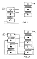
- FIG. 1 It is generally known to store a sequence of time differences between the individual samples in memories, as is shown in FIG. 1.
- the prior art Fig.1 contains the fixed frequency generator f0, which generates a clock, the programmable Taktteilver CT1, the table address counter CT2, which generates the addresses for the sine table TAB, the digital-to-analog converter DAC, which corresponds to the sine table generates analog output voltage U a , the memory address counter CT5 and the memory MEM, which contains the sequence of all divider ratios.
- sequence of time differences can also be calculated in real time by a fast processor, as is known from DE-OS 28 31 739, DE-OS 31 24 924 and others. Furthermore, this sequence of time differences can be generated by a circuit arrangement consisting of multipliers and flip-flops, as described in US Pat. No. 4,217,655, especially for a linearly tunable oscillator.
- the achievable resolution in the frequency range increases with a reduction in the tuning rate of the oscillator.
- a reduced tuning rate of the oscillator increases the required measuring time and requires a larger number of time differences to be generated.
- a disadvantage of digitally tunable oscillators is the enormously large memory requirement, which is already more than 100 megabits with a few minutes of operating time of the oscillator if there is no restriction to a linear tuning rate of the oscillator.
- arithmetic processors there is insufficient speed and accuracy in determining the time differences, as a result of which the entire low-frequency range cannot be tuned by such oscillators and only short-term measurements with low frequency resolution can take place.
- the aim of the invention is to avoid the disadvantages of the analog oscillator, such as poor reproducibility of the setting parameters without using precision components and the restriction to a linear tuning rate.
- the goal is to avoid the problems of digital oscillators such as high costs, low accuracy or lack of versatility in use.
- the object of the invention is to generate the sequence of the time differences between the individual samples in such a way that the tunable oscillator has a low memory requirement, does not require special processors, covers the entire low-frequency range, generates long signals and a freely selectable dependency of the tuning rate allowed by time.
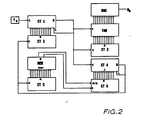
- the problem is solved, starting from the sequential circuit of a clock generator, a programmable clock divider, a table address counter, a sine table and a digital-to-analog converter and the connection of the outputs of a memory address counter to the address inputs of a memory, in that a divider control counter, a down counter and a pre-down counter is arranged such that the clock input of the down counter is connected to the output of the clock divider, the carry output of the down counter is connected to its parallel loading input, to the clock input of the memory address counter and to the clock input of the divider control counter, that the data outputs of the memory are connected to the clock and direction inputs of the up-down counter are connected, that the outputs of the up-down counter are connected to the parallel inputs of the down-counter and that the outputs of the divider are first Your meter are connected to the inputs of the clock divider.
- the function of the circuit is based on the following principle:
- the down counter counts the number of identical successive divisors.
- the up-down counter shows the maximum number of identical successive divisors.
- the divider control counter is used to set the divider ratio of the clock divider.
- the up-down counter When tuning the oscillator slowly, several time differences are of equal size in some frequency ranges due to the time resolution provided by the clock generator.
- the number of the same time differences is stored in the up-down counter. With each newly set time difference of the clock divider, the number is transferred to the down counter. With each completed frequency division of the clock divider, the number of times this division ratio is to be divided is reduced by one and the division ratio that has remained constant is taken over from the divider control counter into the clock divider. If the down counter goes through zero, the divider control counter is changed by one, causing the time difference to change by one the next time the clock divider is loaded. In addition, the memory address counter is incremented, whereby the next memory cell in the memory is addressed.
- the memory cell in turn only contains the information as to whether the newly set time difference is to be used as often as the old time difference as the divider ratio of the clock divider. Accordingly, the up-down counter is not changed, incremented or decremented.
- the memory therefore only contains two bits per possible divider factor. Since the number of different divider factors is only determined by the frequency range and the temporal resolution by the frequency of the clock generator, but not by the frequency of how often this divider factor is used, the memory size is independent of the length of time with which the tunable oscillator should work .
- the clock generator f0 works at 100 MHz.
- the clock divider CT1 consists of three circuits 74 AS 161, which form a programmable 12 bit divider.
- the clock divider CT1 is set by the divider control counter CT3.
- the table address counter CT2, consisting of a synchronous divider chain with six circuits 74 LS 112 and clocked by the sampling clock generated by the clock divider CT1, provides the addresses for the sine table TAB.
- the sine table TAB contains two EPROMS U 2732, at the data outputs of which two D registers 74 AS 374 are connected for synchronization, which are also clocked by the sampling clock.
- the outputs of the D registers are connected to the inputs of the digital-to-analog converter DAC AD 565, which generates the output voltage U a .
- the divider control counter CT3, the down counter CT4, the memory address counter CT5 and the up / down counter CT6 each consist of three circuits CD 4029.
- the down counter CT4 is controlled by the sampling clock and in turn controls the memory address counter CT5 and the divider control counter CT3.
- the memory MEM whose address inputs ADR are addressed by the memory address counter CT5, consists of three CMOS RAMs U 224 and a multiplexer CD 4019, which multiplexes the 4-bit data lines to two bits. In this way, an organization 6k x 2 memory is created.
- the two bit wide data line consisting of the signals V / R and C is evaluated by the up-down counter CT6.
- the initial values of the counters and the content of the RAMs are calculated and preset by a 16-bit PC.
- the circuit is equally suitable for linear and logarithmic tuning characteristics of the oscillator.
- the oscillator can be tuned in the frequency range from 20 Hz to 25 kHz and can generate a signal with a length of up to several hours.
Landscapes
- Stabilization Of Oscillater, Synchronisation, Frequency Synthesizers (AREA)
Applications Claiming Priority (2)
| Application Number | Priority Date | Filing Date | Title |
|---|---|---|---|
| DD331882 | 1989-08-17 | ||
| DD33188289A DD287364A5 (de) | 1989-08-17 | 1989-08-17 | Durchstimmbarer oszillator |
Publications (2)
| Publication Number | Publication Date |
|---|---|
| EP0413404A2 true EP0413404A2 (fr) | 1991-02-20 |
| EP0413404A3 EP0413404A3 (en) | 1991-11-13 |
Family
ID=5611701
Family Applications (1)
| Application Number | Title | Priority Date | Filing Date |
|---|---|---|---|
| EP19900250205 Withdrawn EP0413404A3 (en) | 1989-08-17 | 1990-08-09 | Tunable oscillator |
Country Status (3)
| Country | Link |
|---|---|
| EP (1) | EP0413404A3 (fr) |
| DD (1) | DD287364A5 (fr) |
| HU (1) | HUT54840A (fr) |
Family Cites Families (6)
| Publication number | Priority date | Publication date | Assignee | Title |
|---|---|---|---|---|
| US4144572A (en) * | 1977-08-15 | 1979-03-13 | Rca Corporation | Accurate phase-measuring system using arithmetic synthesis |
| US4217655A (en) * | 1978-08-17 | 1980-08-12 | Owens-Illinois, Inc. | Clock circuit having a swept output frequency |
| US4417218A (en) * | 1981-06-19 | 1983-11-22 | The United States Of America As Represented By The Secretary Of The Navy | Linearizing circuit for a high frequency voltage controlled oscillator |
| US4454486A (en) * | 1981-11-02 | 1984-06-12 | Hewlett-Packard Company | Waveform synthesis using multiplexed parallel synthesizers |
| US4499435A (en) * | 1982-09-30 | 1985-02-12 | Harris Corporation | System for linearizing sweep of voltage controlled oscillator |
| US4829301A (en) * | 1987-11-13 | 1989-05-09 | Ford Aerospace & Communications Corporation | Digital first order hold circuit |
-
1989
- 1989-08-17 DD DD33188289A patent/DD287364A5/de not_active IP Right Cessation
-
1990
- 1990-07-31 HU HU469090A patent/HUT54840A/hu unknown
- 1990-08-09 EP EP19900250205 patent/EP0413404A3/de not_active Withdrawn
Also Published As
| Publication number | Publication date |
|---|---|
| EP0413404A3 (en) | 1991-11-13 |
| DD287364A5 (de) | 1991-02-21 |
| HUT54840A (en) | 1991-03-28 |
| HU904690D0 (en) | 1991-01-28 |
Similar Documents
| Publication | Publication Date | Title |
|---|---|---|
| EP0052847B1 (fr) | Procédé et circuit pour la conversion de la fréquence d'échantillonnage d'une suite d'échantillons en évitant la conversion en un signal continu | |
| DE3500316C2 (fr) | ||
| EP0401562B1 (fr) | Dispositif de conversion d'un signal ayant une première fréquence d'échantillonnage en un signal ayant une deuxième fréquence d'échantillonnage | |
| DE2644885C2 (fr) | ||
| EP0269827A1 (fr) | Appareil de mesure numérique | |
| DE4328269A1 (de) | Vorrichtung und Verfahren zur Analyse von ILS-Signalen | |
| WO1980001206A1 (fr) | Procede de mesure de puissance electrique | |
| EP0215810B1 (fr) | Circuit d'obtention d'une valeur moyenne | |
| DE3586366T2 (de) | Verfahren und schaltung zur erzeugung eines zeitvariablen signals. | |
| DE3917020C2 (fr) | ||
| DE3785654T2 (de) | Tonsignalerzeugungsvorrichtung mit einem digitalen Filter. | |
| WO1997025773A1 (fr) | Procede et dispositif pour la modulation de frequence d'un signal haute frequence | |
| DE19750349C2 (de) | Netzwerk-Analysator | |
| EP0036074A1 (fr) | Synthétiseur de signaux périodiques, en particulier pour instrument de musique | |
| DE2612238C3 (de) | Verfahren zur Ermittlung der Vektor-Komponenten einer Schwingung und Schaltungsanordnung zur Durchführung des Verfahrens | |
| DE3124964C2 (fr) | ||
| DE1952235C2 (de) | Frequenzmesser zur Messung der Differenz zweier unbekannter Eingangsfrequenzen | |
| DE2453873A1 (de) | Fourier-analysator | |
| DE19544642C1 (de) | Digitaler Phasenschieber | |
| DE4343986C2 (de) | Digitaler Sinuswellengenerator | |
| DD287364A5 (de) | Durchstimmbarer oszillator | |
| EP0367860B1 (fr) | Procédé de mesure de l'amplitude d'un signal électrique périodique G(t) dans une plage de signaux U(t) | |
| DE2429744C3 (de) | Schaltung zur Synthese von Signalen bestimmter, vorgegebener Bandbreite | |
| EP0015424A1 (fr) | Circuit pour produire successivement les valeurs de fonction de plusieurs oscillations dont les fréquences de répétition correspondent à N fois la valeur d'une fréquence fondamentale | |
| DE3907781A1 (de) | Verfahren und vorrichtung zur digitalen phasenmessung |
Legal Events
| Date | Code | Title | Description |
|---|---|---|---|
| PUAI | Public reference made under article 153(3) epc to a published international application that has entered the european phase |
Free format text: ORIGINAL CODE: 0009012 |
|
| AK | Designated contracting states |
Kind code of ref document: A2 Designated state(s): AT CH DE DK FR GB LI |
|
| PUAL | Search report despatched |
Free format text: ORIGINAL CODE: 0009013 |
|
| AK | Designated contracting states |
Kind code of ref document: A3 Designated state(s): AT CH DE DK FR GB LI |
|
| STAA | Information on the status of an ep patent application or granted ep patent |
Free format text: STATUS: THE APPLICATION IS DEEMED TO BE WITHDRAWN |
|
| 18D | Application deemed to be withdrawn |
Effective date: 19920514 |