EP0413557A2 - Appareil de traitement d'image - Google Patents
Appareil de traitement d'image Download PDFInfo
- Publication number
- EP0413557A2 EP0413557A2 EP90308930A EP90308930A EP0413557A2 EP 0413557 A2 EP0413557 A2 EP 0413557A2 EP 90308930 A EP90308930 A EP 90308930A EP 90308930 A EP90308930 A EP 90308930A EP 0413557 A2 EP0413557 A2 EP 0413557A2
- Authority
- EP
- European Patent Office
- Prior art keywords
- colour
- coefficient
- image
- value
- difference signals
- Prior art date
- Legal status (The legal status is an assumption and is not a legal conclusion. Google has not performed a legal analysis and makes no representation as to the accuracy of the status listed.)
- Granted
Links
Images




Classifications
-
- H—ELECTRICITY
- H04—ELECTRIC COMMUNICATION TECHNIQUE
- H04N—PICTORIAL COMMUNICATION, e.g. TELEVISION
- H04N9/00—Details of colour television systems
- H04N9/64—Circuits for processing colour signals
- H04N9/68—Circuits for processing colour signals for controlling the amplitude of colour signals, e.g. automatic chroma control circuits
Definitions
- This invention relates to image processing apparatus that processes an input image signal to generate a print signal.
- a video signal (still image signal) of one frame obtained from a video source such as a television camera, video disc electronic still camera or the like is supplied to an image processor, which then processes the input image signal to generate a desired print signal.
- the print signal is supplied to a printing device to control the printing of the image.
- FIG. 9 is a block diagram of an example of an image processing system, comprising an image signal output unit 1 for generating a video signal (still image) of one frame.
- the image signal output unit 1 may comprise or respond to a television camera or the like.
- the still image signal derived therefrom is fed to an image processor 2, and is processed in compliance with the signals generated by a processing control console 2A.
- the image processing executed with respect to the supplied original still image signal includes noise reduction, luminance control, colour saturation control, image conversion (enlargement, reduction, rotation, image size change) and so forth.
- image processing is known per se and thus is not described in detail herein.
- the processing control console 2A comprises input means such as a keyboard and a mouse and display means including a processing operation monitor, an image monitor and so forth.
- a printer 3 is supplied with the output signal of the image processor 2 suitably converted to print signals of, for example, four colours C, M, Y and K (cyan, magenta, yellow and black) after completion of the image processing, whereby the operation of printing the colour image is executed by the printer 3.
- C, M, Y and K cyan, magenta, yellow and black
- the colour saturation can be improved by individually controlling the three primary colour signals R, G, B (red, green, blue) or C, M, Y (cyan, magenta, yellow) in the printer 3.
- R, G, B red, green, blue
- image processing apparatus having a colour saturation controller for processing a colour image signal to be printed, said apparatus comprising: input means for providing an incoming colour image signal; colour difference means responsive to said input means for deriving colour difference signals from said incoming colour image signal; detecting means responsive to said colour difference means for detecting a minimum difference value between an allowable dynamic range of colour difference signals and said derived colour difference signals; coefficient setting means responsive to said detecting means for generating a coefficient value based on said detected minimum difference value; and multiplying means response to said coefficient setting means for correcting the levels of said derived colour difference signals by multiplying said generated coefficient value and said colour difference signals.
- colour difference digital data are detected from a still image signal of one frame.
- the still image signal is composed of a luminance signal and two colour difference signals, and a coefficient is set to a proper value which is selected so as not to cause any overflow of the colour difference data beyond an allowable dynamic range (00000000 to 11111111 in an 8-bit arrangement) when the coefficient is employed to multiply the colour difference data.
- the colour difference data relative to each pixel of one frame are multiplied by a real number corresponding to such coefficient value, whereby the dynamic range of the input colour difference signals is extended.
- the colour saturation can be easily, automatically and directly corrected without changing the colour phase of the image signal.
- the image processing apparatus further comprises means for limiting the coefficient value obtained from the coefficient value generating means.
- Setting the coefficient to a value that does not cause any overflow can be accomplished by the provision of a coefficient-calculating data detection means for detecting a minimum difference value (difference data) between the colour difference data in each pixel and the upper limit value (for example, 11111111) or the lower limit value (for example, 00000000) of the dynamic range; and a coefficient setting means for calculating, on the basis of the detected minimum difference value, a proper coefficient value which is capable of reducing the minimum value (difference data) to zero by multiplying the colour difference data.
- a coefficient-calculating data detection means for detecting a minimum difference value (difference data) between the colour difference data in each pixel and the upper limit value (for example, 11111111) or the lower limit value (for example, 00000000) of the dynamic range
- a coefficient setting means for calculating, on the basis of the detected minimum difference value, a proper coefficient value which is capable of reducing the minimum value (difference data) to zero by multiplying the colour difference data.
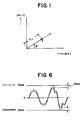
- the colour phase or hue is represented, as graphically shown in Figure 1, by an angle ⁇ which is formed by the B-Y axis and a vector C of the relevant colour in plane coordinates with R-Y and B-Y plotted as mutually orthogonal axes.
- the colour saturation is represented by
- the colour saturation of the image signal can be improved by multiplying the colour difference signals R-Y and B-Y and the real number (coefficient value) in the processing means.
- the exemplary system of Figure 2 is constructed so that an image signal transmitted in a suitable way can be processed and printed, for example, as a photograph in a newspaper. First a description will be given with regard to such image processing system.
- Figure 2 shows an imaging device 10 such as a television camera; a video reproducer 11 (TV monitor) for reproducing the video image picked up by the imaging device 10; and a still picture transmitter 12 capable of transmitting, via a telephone line, a communications satellite link or the like, a desired picture (colour video signal of one frame) out of the entire picked-up video image.
- an imaging device 10 such as a television camera
- a video reproducer 11 TV monitor
- a still picture transmitter 12 capable of transmitting, via a telephone line, a communications satellite link or the like, a desired picture (colour video signal of one frame) out of the entire picked-up video image.
- a still picture receiver 20 receives the picture derived from the still picture transmitter 12, and a receiving monitor 21 displays the received picture.
- the still image signal received by the picture receiver 20 comprises a luminance signal (Y signal) and two colour difference signals (R-Y and B-Y signals) of one frame, and is supplied sequentially to an image processor 30.
- a still image signal source such as a video disc unit, videotape recorder, television receiver or the like is provided as an alternative source of a still image signal input to the image processor 30.
- the image processor 30 is such as to perform various operations on the image signal supplied thereto, such as storing the image signal, processing the image, and generating a suitable print signal.
- a console 40 comprises a control display 41, a keyboard 42, a mouse 43 and a processed image monitor 44. This console 40 is manipulated by an operator to execute various operations of the image processor 30.
- a printer 50 is supplied with the print image data that are processed by the image processor 30 and converted to print colour signals of, for example, C, M, Y and K (cyan, magenta, yellow and black) and then prints the desired image.
- C, M, Y and K cyan, magenta, yellow and black
- an image obtained by picking up, for example, a news scene and phototelegraphed by the still picture transmitter 12 is immediately processed so that is then supplied directly to the printer 50.
- the apparatus is effectively utilizable under on-line control for an editing system or the like employed, for example, by a newspaper publishing company.
- the image processor 30 embodying the present invention is constructed as illustrated in Figure 3 and serves as a host computer to the entire system. That is, the image processor 30 comprises a program ROM 31 wherein various control programs are stored; an input image memory (hard disc) 32 wherein image data supplied from an image source such as the still picture receiver 20 is sequentially stored; a central processing unit (CPU) 33 serving as a controller; an output image memory 34 for storing an output image signal converted to individual colour signals C, M, Y and K (cyan, magenta, yellow and black) after being processed for printing; and an input-output interface 35 for transferring the image data to or from the console 40.
- the CPU 33 comprises a system controller 33A for controlling the operations of the component elements in accordance with an operation program, a processing unit 33B for executing various processings, and a work memory (main storage memory) 33C.
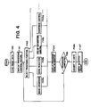
- the still image signal supplied to the image processor 30 is sequentially stored in the hard disc 32. Then the image data are read out from the hard disc 32 in accordance with requirements, and the image processing routines as shown in a flowchart of Figure 4 are executed principally by operations in the CPU 33.
- the image processing procedure first the image data to be processed are loaded from the hard disc 32 into the CPU 33 [F100], and then the processing control picture representing the contents to be processed is displayed in the form, for example, of a menu on the control display 41 of the console 40 [F101].
- the processing function is determined [F102] in response to an input from the operator via the keyboard 42 or the mouse 43, and then the determined processing routine is executed. More specifically, there is executed one function selected from the functions of image conversion, noise reduction, colour saturation control, sharpness control and so forth. These functions are denoted by F103a, F103b, F103c, F103d ..., respectively.
- F103a, F103b, F103c, F103d ... As for the image conversion in F103a, any of enlargement/reduction, centre position change, rotation, image size change and so forth can be executed with respect to the original image supplied as an input.
- the functions F103a, F103b, F103c, F103d ... are shown in parallel in the flowchart of Figure 4, such functions may of course be executed sequentially in any order.
- the image signal processed in F103 is supplied to the processed image monitor 44 ( Figure 2) and displayed [F104] so that the operator can check the current stage in the processing procedure.
- the operator manipulates the keyboard 42 to the mouse 43 of the console 40 to select the processing routine appropriate to the new function [F105 ⁇ F102].
- the image signal is converted to C, M, Y and K colour signals to be printed [F106], and then such signals are stored as output data in the output image memory 34 [F107]. Subsequently, the data thus stored are supplied to the printer 50 ( Figure 2) from the output image memory 34 ( Figure 3) either automatically or by manipulation of the console 40, whereby one full colour image is printed with the image signals of four colours C, M, Y and K.
- Such image processing apparatus can control the colour saturation [F103c] automatically in a highly effective way.
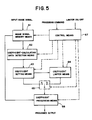
- Figure 5 is a function block diagram of means for realizing the colour saturation control in the preferred embodiment of the invention.
- Such function blocks are preferably constituted by software in the CPU 33.
- Image signal memory means 61 holds Y, R-Y and B-Y digital image signals (in this embodiment, 8-bit signals) of one frame read out from the hard disc 32 for processing.
- Coefficient-calculating data detection means 62 detects from the R-Y signal data and the B-Y signal data stored in the image signal memory means 61, a maximum colour difference data value or a minimum colour difference data value (within one frame of the image) which is the closest to the upper limit value 11111111 or the lower limit value 00000000 of the dynamic range, and then supplies coefficient calculating data based on the difference between the detected value and the upper or lower limit value.
- the operation is performed in such a manner that, with respect to the colour difference signal represented graphically by a solid line in Figure 6, any data greater than the centre value C are compared with the upper limit value D max to obtain the difference therebetween, while any data smaller than the centre value C are compared with the lower limit value D min to obtain the difference therebetween , and the minimum difference data d min are used as the coefficient calculating data.
- Coefficient setting means 63 sets a proper coefficient value on the basis of the coefficient calculating data d min supplied thereto. As will be described later, the coefficient value is set so that the results of multiplying it by the R-Y and B-Y data never exceed, in absolute value measured from the centre value C, the upper limit value D max or the lower limit value D min .
- Coefficient limiter means 64 provides as an output a predetermined coefficient value when the set coefficient value is in excess of a certain limit value.
- Coefficient processing means 66 extends the dynamic range of the colour difference data by multiplying the set coefficient value and the R-Y and B-Y data. Under the control of the control means 67, switching means 65 connects either the coefficient setting means 63 or the coefficient limiter means 64 to the coefficient processing means 66. The multiplication of the coefficient value is executed for extension towards the upper limit value D max with respect to any data greater than the centre value C, or towards the lower limit value D min with respect to any data smaller than the centre value C.
- control means 67 receives a control execution command from the console 40 and also on/off data therefrom for the coefficient limiter means 64.
- the coefficient-calculating data detection means 62 When the colour saturation control is started [F200] after the image data have been loaded and stored in the image signal memory means 61, the coefficient-calculating data detection means 62 first detects the R-Y data to determine the minimum difference data d min R-Y as described previously [F201] and then detects the B-Y data to determine the difference data d min B-Y [F202]. The smaller one of these values is detected [F203] and supplied as coefficient calculating data X to the coefficient setting means 63 [F204, F205].
- the coefficient setting means 63 sets a coefficient value K which is capable of extending the dynamic range of the R-Y and B-Y signals without, however, causing any overflow [F206]. More specifically, there is determined a proper coefficient value K for adjusting the maximum value or minimum value in the colour difference data to D max or D min .
- Such coefficient value K can be obtained from the following calculation:
- the coefficient limiter means 64 When the coefficient limiter means 64 is in its off-state, the coefficient value K thus obtained is supplied directly via a contact a of the switching means 65 to the coefficient processing means 66, thereby to multiply the colour difference data in each pixel [F207 ⁇ F208 ⁇ F209].
- the colour difference signal represented by a solid line in Figure 6 is converted to a signal whose dynamic range is extended as indicated by a dotted line in Figure 6.
- the colour difference data multiplied by the coefficient value K never exceed the value D max and D min as described previously, thus avoiding the partial loss of the colour saturation information that would result in case of overflow.
- the aforementioned coefficient limiter means 64 is additionally provided to limit the coefficient value. More specifically, when the coefficient limiter means 64 is in its on-state, a decision is made in F210 as to whether the set coefficient value K is in excess of a predetermined limit value k L . If the set coefficient value K is beyond K L or -K L as graphically shown in Figure 8(a), the predetermined coefficient value is supplied to the coefficient processing means 66 [F211]. Such limitation may be effected gradually as shown in Figure 8(b).
- the image processing apparatus of this embodiment is constructed so that the dynamic range of the colour difference signals is automatically extended within an allowable range, whereby it is unnecessary for an operator to supply as inputs any numerical value or the like, and there is obtainable a complete printed image wherein satisfactory colour saturation is maintained. Furthermore, because of the limitation of the coefficient value by the coefficient limiter means, there never occurs an undesired state where the colour saturation is increased to such an extent that saturation information is lost.
- the coefficient setting operation is not restricted to the example shown in the flowchart of Figure 7 and the calculation method mentioned above; any other method may be employed provided that it obtains a coefficient suited to convert the colour difference signals within the allowable dynamic range.
Landscapes
- Engineering & Computer Science (AREA)
- Multimedia (AREA)
- Signal Processing (AREA)
- Facsimile Image Signal Circuits (AREA)
- Color Image Communication Systems (AREA)
- Image Processing (AREA)
- Processing Of Color Television Signals (AREA)
- Processing Or Creating Images (AREA)
Applications Claiming Priority (2)
| Application Number | Priority Date | Filing Date | Title |
|---|---|---|---|
| JP209655/89 | 1989-08-15 | ||
| JP1209655A JP3057255B2 (ja) | 1989-08-15 | 1989-08-15 | 画像処理装置及び画像処理方法 |
Publications (3)
| Publication Number | Publication Date |
|---|---|
| EP0413557A2 true EP0413557A2 (fr) | 1991-02-20 |
| EP0413557A3 EP0413557A3 (en) | 1992-05-27 |
| EP0413557B1 EP0413557B1 (fr) | 1996-03-06 |
Family
ID=16576404
Family Applications (1)
| Application Number | Title | Priority Date | Filing Date |
|---|---|---|---|
| EP90308930A Expired - Lifetime EP0413557B1 (fr) | 1989-08-15 | 1990-08-14 | Appareil de traitement d'image |
Country Status (4)
| Country | Link |
|---|---|
| US (1) | US5144420A (fr) |
| EP (1) | EP0413557B1 (fr) |
| JP (1) | JP3057255B2 (fr) |
| DE (1) | DE69025672T2 (fr) |
Cited By (4)
| Publication number | Priority date | Publication date | Assignee | Title |
|---|---|---|---|---|
| EP0818920A1 (fr) * | 1996-07-10 | 1998-01-14 | Fujifilm Electronic Imaging Limited | Correction de couleurs |
| EP0878777A3 (fr) * | 1997-05-09 | 1998-12-23 | Xerox Corporation | Procédé d'amélioration d'images à assortiment de couleurs réduit |
| EP0843464A3 (fr) * | 1996-11-13 | 2000-11-29 | Seiko Epson Corporation | Système et procédé de traitement d'images |
| CN102740116A (zh) * | 2011-04-08 | 2012-10-17 | 索尼公司 | 图像属性检测 |
Families Citing this family (5)
| Publication number | Priority date | Publication date | Assignee | Title |
|---|---|---|---|---|
| DE69315285T2 (de) * | 1992-09-02 | 1998-05-28 | Matsushita Electric Ind Co Ltd | Vorrichtung zum Verarbeiten eines Bildsignals |
| US5450217A (en) * | 1994-05-23 | 1995-09-12 | Xerox Corporation | Image-dependent color saturation correction in a natural scene pictorial image |
| JP2830871B2 (ja) * | 1996-11-18 | 1998-12-02 | 日本電気株式会社 | 画像の色補正装置及び色補正プログラムを記録した記録媒体 |
| EP3467816A1 (fr) * | 2010-02-24 | 2019-04-10 | Dolby Laboratories Licensing Corp. | Procédés et appareil de gestion d'affichage |
| EP2977958A1 (fr) * | 2014-07-22 | 2016-01-27 | Thomson Licensing | Procédé et appareil pour le traitement d'une image |
Family Cites Families (9)
| Publication number | Priority date | Publication date | Assignee | Title |
|---|---|---|---|---|
| SU566408A1 (ru) * | 1975-07-11 | 1977-07-25 | Предприятие П/Я М-5876 | Канал цветоразностного сигнала дл цветного телевизионного приемника |
| JPS6052429B2 (ja) * | 1979-02-28 | 1985-11-19 | 大日本スクリ−ン製造株式会社 | 色修正演算方法 |
| JPS60188A (ja) * | 1983-06-16 | 1985-01-05 | Sony Corp | Acc回路 |
| US4673970A (en) * | 1984-06-08 | 1987-06-16 | Matsushita Electric Industrial Co., Ltd. | Chrominance signal processing system |
| GB8422988D0 (en) * | 1984-09-12 | 1984-10-17 | Crosfield Electronics Ltd | Colour enhancement |
| FR2575884B1 (fr) * | 1985-01-08 | 1988-07-08 | Thomson Video Equip | Dispositif pour reduire la dynamique de trois signaux de couleur representant une image |
| DE3629403C2 (de) * | 1986-08-29 | 1994-09-29 | Agfa Gevaert Ag | Verfahren zur Korrektur der Farbsättigung bei der elektronischen Bildverarbeitung |
| GB2202708B (en) * | 1987-03-16 | 1991-05-29 | Mitsubishi Electric Corp | Color converting device |
| US4884130A (en) * | 1988-04-29 | 1989-11-28 | Minnesota Mining And Manufacturing Company | Method of describing a color in a triaxial planar vector color space |
-
1989
- 1989-08-15 JP JP1209655A patent/JP3057255B2/ja not_active Expired - Lifetime
-
1990
- 1990-08-10 US US07/565,245 patent/US5144420A/en not_active Expired - Fee Related
- 1990-08-14 DE DE69025672T patent/DE69025672T2/de not_active Expired - Fee Related
- 1990-08-14 EP EP90308930A patent/EP0413557B1/fr not_active Expired - Lifetime
Cited By (11)
| Publication number | Priority date | Publication date | Assignee | Title |
|---|---|---|---|---|
| EP0818920A1 (fr) * | 1996-07-10 | 1998-01-14 | Fujifilm Electronic Imaging Limited | Correction de couleurs |
| EP0843464A3 (fr) * | 1996-11-13 | 2000-11-29 | Seiko Epson Corporation | Système et procédé de traitement d'images |
| US6351558B1 (en) | 1996-11-13 | 2002-02-26 | Seiko Epson Corporation | Image processing system, image processing method, and medium having an image processing control program recorded thereon |
| US6539111B2 (en) | 1996-11-13 | 2003-03-25 | Seiko Epson Corporation | Image processing system, image processing method, and medium having an image processing control program recorded thereon |
| US6754381B2 (en) | 1996-11-13 | 2004-06-22 | Seiko Epson Corporation | Image processing system, image processing method, and medium having an image processing control program recorded thereon |
| EP1587302A1 (fr) * | 1996-11-13 | 2005-10-19 | Seiko Epson Corporation | Système et procédé de traitement d'images, et support sur lequel est enregistré un logiciel de commande de traitement d'image |
| EP1587300A3 (fr) * | 1996-11-13 | 2005-11-30 | Seiko Epson Corporation | Système et procédé de traitement d'images et support pour le programme correspondant |
| US7155060B2 (en) | 1996-11-13 | 2006-12-26 | Seiko Epson Corporation | Image processing system, image processing method, and medium having an image processing control program recorded thereon |
| US7512263B2 (en) | 1996-11-13 | 2009-03-31 | Seiko Epson Corporation | Image processing system, image processing method, and medium having an image processing control program recorded thereon |
| EP0878777A3 (fr) * | 1997-05-09 | 1998-12-23 | Xerox Corporation | Procédé d'amélioration d'images à assortiment de couleurs réduit |
| CN102740116A (zh) * | 2011-04-08 | 2012-10-17 | 索尼公司 | 图像属性检测 |
Also Published As
| Publication number | Publication date |
|---|---|
| JP3057255B2 (ja) | 2000-06-26 |
| DE69025672T2 (de) | 1996-07-25 |
| JPH0373672A (ja) | 1991-03-28 |
| EP0413557B1 (fr) | 1996-03-06 |
| US5144420A (en) | 1992-09-01 |
| EP0413557A3 (en) | 1992-05-27 |
| DE69025672D1 (de) | 1996-04-11 |
Similar Documents
| Publication | Publication Date | Title |
|---|---|---|
| US6476793B1 (en) | User interactive copy processing for selective color conversion or adjustment without gradation loss, and adjacent non-selected-color areas are not affected | |
| US6031543A (en) | Image processing apparatus for correcting color space coordinates and method | |
| US7426299B2 (en) | Image processing method, apparatus and memory medium therefor | |
| EP0090596B1 (fr) | Système de correction des signaux d'image | |
| US6778186B2 (en) | Method of and apparatus for carrying out gray conversion on color image | |
| US5414537A (en) | Color image processing method and apparatus | |
| US5717839A (en) | Image processor and printer having correction table data for an external source transferred to the printer | |
| EP0070680B1 (fr) | Reproduction d'images en couleurs | |
| EP0413557B1 (fr) | Appareil de traitement d'image | |
| US20080018920A1 (en) | Image processing apparatus | |
| JPH10334230A (ja) | 画像強調処理の制御方法 | |
| US5847848A (en) | Image processing apparatus which previews both input and edited image data | |
| US6917444B1 (en) | Image correction for color image | |
| JP2964492B2 (ja) | 画像処理装置及び画像処理方法 | |
| US5107347A (en) | Image data inputting system for image processing apparatus | |
| JPH05205039A (ja) | カラー画像処理方法およびカラー画像処理装置 | |
| EP0620692B1 (fr) | Circuit de détection de teinte | |
| JP3000723B2 (ja) | 色修正状態の表示装置 | |
| EP0791266B1 (fr) | Nouveau calcul du noir destine a des corrections arbitraires de teinte, saturation et luminance dans un espace des couleurs cmj | |
| JP3104361B2 (ja) | 画像処理装置及び画像処理システム | |
| JPH05344328A (ja) | 印刷装置 | |
| JPH07131807A (ja) | 色補正装置 | |
| JPH0358173A (ja) | 画像処理システムの処理方法 | |
| JP3372562B2 (ja) | 画像処理装置およびその方法 | |
| JP3166974B2 (ja) | 画像処理方法及びそれを適用した画像形成システム |
Legal Events
| Date | Code | Title | Description |
|---|---|---|---|
| PUAI | Public reference made under article 153(3) epc to a published international application that has entered the european phase |
Free format text: ORIGINAL CODE: 0009012 |
|
| AK | Designated contracting states |
Kind code of ref document: A2 Designated state(s): DE FR GB |
|
| PUAL | Search report despatched |
Free format text: ORIGINAL CODE: 0009013 |
|
| AK | Designated contracting states |
Kind code of ref document: A3 Designated state(s): DE FR GB |
|
| 17P | Request for examination filed |
Effective date: 19921005 |
|
| 17Q | First examination report despatched |
Effective date: 19940803 |
|
| GRAA | (expected) grant |
Free format text: ORIGINAL CODE: 0009210 |
|
| AK | Designated contracting states |
Kind code of ref document: B1 Designated state(s): DE FR GB |
|
| REF | Corresponds to: |
Ref document number: 69025672 Country of ref document: DE Date of ref document: 19960411 |
|
| ET | Fr: translation filed | ||
| PGFP | Annual fee paid to national office [announced via postgrant information from national office to epo] |
Ref country code: GB Payment date: 19960805 Year of fee payment: 7 |
|
| PLBE | No opposition filed within time limit |
Free format text: ORIGINAL CODE: 0009261 |
|
| STAA | Information on the status of an ep patent application or granted ep patent |
Free format text: STATUS: NO OPPOSITION FILED WITHIN TIME LIMIT |
|
| 26N | No opposition filed | ||
| PG25 | Lapsed in a contracting state [announced via postgrant information from national office to epo] |
Ref country code: GB Free format text: LAPSE BECAUSE OF NON-PAYMENT OF DUE FEES Effective date: 19970814 |
|
| GBPC | Gb: european patent ceased through non-payment of renewal fee |
Effective date: 19970814 |
|
| PGFP | Annual fee paid to national office [announced via postgrant information from national office to epo] |
Ref country code: FR Payment date: 20020808 Year of fee payment: 13 |
|
| PGFP | Annual fee paid to national office [announced via postgrant information from national office to epo] |
Ref country code: DE Payment date: 20020821 Year of fee payment: 13 |
|
| PG25 | Lapsed in a contracting state [announced via postgrant information from national office to epo] |
Ref country code: DE Free format text: LAPSE BECAUSE OF NON-PAYMENT OF DUE FEES Effective date: 20040302 |
|
| PG25 | Lapsed in a contracting state [announced via postgrant information from national office to epo] |
Ref country code: FR Free format text: LAPSE BECAUSE OF NON-PAYMENT OF DUE FEES Effective date: 20040430 |
|
| REG | Reference to a national code |
Ref country code: FR Ref legal event code: ST |