EP0413565B1 - Système de refroidissement pour un dispositif semi-conducteur, module semi-conducteur ayant un tel système et utilisant un corps de refroidissement thermoconducteur - Google Patents
Système de refroidissement pour un dispositif semi-conducteur, module semi-conducteur ayant un tel système et utilisant un corps de refroidissement thermoconducteur Download PDFInfo
- Publication number
- EP0413565B1 EP0413565B1 EP90308941A EP90308941A EP0413565B1 EP 0413565 B1 EP0413565 B1 EP 0413565B1 EP 90308941 A EP90308941 A EP 90308941A EP 90308941 A EP90308941 A EP 90308941A EP 0413565 B1 EP0413565 B1 EP 0413565B1
- Authority
- EP
- European Patent Office
- Prior art keywords
- group
- cooling system
- thermally conductive
- fluorine
- conductive member
- Prior art date
- Legal status (The legal status is an assumption and is not a legal conclusion. Google has not performed a legal analysis and makes no representation as to the accuracy of the status listed.)
- Expired - Lifetime
Links
Images

Classifications
-
- H—ELECTRICITY
- H10—SEMICONDUCTOR DEVICES; ELECTRIC SOLID-STATE DEVICES NOT OTHERWISE PROVIDED FOR
- H10W—GENERIC PACKAGES, INTERCONNECTIONS, CONNECTORS OR OTHER CONSTRUCTIONAL DETAILS OF DEVICES COVERED BY CLASS H10
- H10W40/00—Arrangements for thermal protection or thermal control
- H10W40/70—Fillings or auxiliary members in containers or in encapsulations for thermal protection or control
- H10W40/77—Auxiliary members characterised by their shape
- H10W40/774—Pistons, e.g. spring-loaded members
-
- C—CHEMISTRY; METALLURGY
- C10—PETROLEUM, GAS OR COKE INDUSTRIES; TECHNICAL GASES CONTAINING CARBON MONOXIDE; FUELS; LUBRICANTS; PEAT
- C10M—LUBRICATING COMPOSITIONS; USE OF CHEMICAL SUBSTANCES EITHER ALONE OR AS LUBRICATING INGREDIENTS IN A LUBRICATING COMPOSITION
- C10M105/00—Lubricating compositions characterised by the base-material being a non-macromolecular organic compound
- C10M105/56—Lubricating compositions characterised by the base-material being a non-macromolecular organic compound containing nitrogen
- C10M105/68—Amides; Imides
-
- C—CHEMISTRY; METALLURGY
- C10—PETROLEUM, GAS OR COKE INDUSTRIES; TECHNICAL GASES CONTAINING CARBON MONOXIDE; FUELS; LUBRICANTS; PEAT
- C10M—LUBRICATING COMPOSITIONS; USE OF CHEMICAL SUBSTANCES EITHER ALONE OR AS LUBRICATING INGREDIENTS IN A LUBRICATING COMPOSITION
- C10M105/00—Lubricating compositions characterised by the base-material being a non-macromolecular organic compound
- C10M105/76—Lubricating compositions characterised by the base-material being a non-macromolecular organic compound containing silicon
-
- C—CHEMISTRY; METALLURGY
- C10—PETROLEUM, GAS OR COKE INDUSTRIES; TECHNICAL GASES CONTAINING CARBON MONOXIDE; FUELS; LUBRICANTS; PEAT
- C10M—LUBRICATING COMPOSITIONS; USE OF CHEMICAL SUBSTANCES EITHER ALONE OR AS LUBRICATING INGREDIENTS IN A LUBRICATING COMPOSITION
- C10M107/00—Lubricating compositions characterised by the base-material being a macromolecular compound
- C10M107/38—Lubricating compositions characterised by the base-material being a macromolecular compound containing halogen
-
- H—ELECTRICITY
- H10—SEMICONDUCTOR DEVICES; ELECTRIC SOLID-STATE DEVICES NOT OTHERWISE PROVIDED FOR
- H10W—GENERIC PACKAGES, INTERCONNECTIONS, CONNECTORS OR OTHER CONSTRUCTIONAL DETAILS OF DEVICES COVERED BY CLASS H10
- H10W72/00—Interconnections or connectors in packages
- H10W72/071—Connecting or disconnecting
- H10W72/072—Connecting or disconnecting of bump connectors
- H10W72/07251—Connecting or disconnecting of bump connectors characterised by changes in properties of the bump connectors during connecting
-
- H—ELECTRICITY
- H10—SEMICONDUCTOR DEVICES; ELECTRIC SOLID-STATE DEVICES NOT OTHERWISE PROVIDED FOR
- H10W—GENERIC PACKAGES, INTERCONNECTIONS, CONNECTORS OR OTHER CONSTRUCTIONAL DETAILS OF DEVICES COVERED BY CLASS H10
- H10W72/00—Interconnections or connectors in packages
- H10W72/20—Bump connectors, e.g. solder bumps or copper pillars; Dummy bumps; Thermal bumps
-
- H—ELECTRICITY
- H10—SEMICONDUCTOR DEVICES; ELECTRIC SOLID-STATE DEVICES NOT OTHERWISE PROVIDED FOR
- H10W—GENERIC PACKAGES, INTERCONNECTIONS, CONNECTORS OR OTHER CONSTRUCTIONAL DETAILS OF DEVICES COVERED BY CLASS H10
- H10W72/00—Interconnections or connectors in packages
- H10W72/851—Dispositions of multiple connectors or interconnections
- H10W72/874—On different surfaces
- H10W72/877—Bump connectors and die-attach connectors
Definitions
- This invention relates to a cooling system for a semiconductor element, e.g. a semiconductor chip, to a semiconductor module containing a plurality of semiconductor elements cooled by such cooling systems and to a thermally conductive member for use in such a cooling system.
- the invention is especially useful in the cooling of high-density integrated circuit elements.
- a cooling device for use in a large-scale computer system is disclosed in JP-A-63-250848 (1988).
- a heat conducting intermediate block is slidably mounted on an integrated circuit chip, which is a heat generator, so that the movement of the chip such as thermal expansion and contraction due to the generated heat is absorbed by the transverse or vertical movement of the heat-conducting intermediate block so as to constantly maintain the contact of the cooling portion and the heat generation portion, thereby reducing thermal resistance.
- a high conductivity grease is used at the contact region, to improve conduction.
- EP-A-288 183 illustrates a similar construction having a thermally conductive member slidably arranged between spaced surfaces. It is proposed that a resin is interposed between the member and one of the surfaces.
- JP-A-58-91665 (1983) discloses another cooling structure in which a cooling piston is slidably mounted on an integrated circuit chip, which is a heat generator. The piston is pushed by a spring so as to keep in close contact.
- This device is not structurally completed unless a heat transfer grease is used between the cooling piston and a heat transfer cylinder in which the piston is located and which is cooled by a refrigerant carrier, and between the cooling piston and the integrated circuit chip, but an appropriate contact pressure is applied by a spring and a good heat transfer property is obtained.
- a cooling system for cooling a semiconductor element comprising a heat sink and a heat flow path for removing heat from the element to said heat sink.
- the heat flow path includes two opposed spaced surfaces, one of said surfaces being in thermal connection with said heat sink, the other surface being in thermal connection with said semiconductor element, and an intermediate thermally conductive member interposed between the two surfaces for conducting the heat between the two surfaces and slidable relative to at least one of the surfaces at a region of sliding contact.
- At the region of sliding contact either or both of the thermally conductive member and the surface contacted thereby carries a fixed thin film comprising fluorine-containing lubricant.
- thermoly conductive member as set out in Claim 20.
- the present invention can provide improvement of the lubricating property of the cooling system without impairing the heat transfer property.
- the thin film comprising fluorine containing lubricant is preferably not more than 5 ⁇ m, more preferably 2 nm to 100 nm thick.
- the intermediate thermally conductive member has such a thin film comprising fluorine containing lubricant on at least one of its surfaces.
- the thin film may additionally or alternatively be provided on a surface engaged by the intermediate member, e.g. a surface of a block cooled by a coolant.
- the lubricant may be chemically bonded to the surface carrying the thin film.
- the lubricant may constitute the film.
- the thin film may comprise a support layer, e.g. an organic polymer formed in situ , and fluorine-containing lubricant molecularly anchored in the support layer.
- the chemical bonding to the surface may be provided by a silanol type bond.
- the preferred thickness of the film is 2 to 10 nm in this case.
- a fluorine compound having a silanol group at the end a compound represented by the following general formula is preferred: Rf - R - R′ - S wherein Rf represents a perfluoropolyoxyalkyl group, R a divalent group selected from an amido group, an ester group and a methylol group, R′ an alkylene group, amino-substituted alkylene group or an aromatic group-substituted alkylene group, and S a silanol group.
- Rf represents a perfluoropolyoxyalkyl group
- R′ an alkylene group, amino-substituted alkylene group or an aromatic group-substituted alkylene group
- S
- the silanol group S may typically be Si-OR or Si(OR)2 etc., and typically reacts with -OH groups on the surface of the metal or ceramic member to which the lubricant is bonded to form silanol linkage (Si-O-X, where X is the substrate).
- Si-O-X silanol linkage
- fluorine compounds containing a silanol group at the end are fluorine compounds having the following structures: Rf - CONH - C3H6 - Si(OC2H5)3, Rf - CONH - C2H4NHC3H6 - Si(OCH3)2(CH 3) , Rf - CONH - C2H4NHC3H6 - Si(OCH3)3, Rf - CH2O - C3H6 - Si(OCH3)3, Rf - COO - C3H6 - OC3H6 - Si(OCH3)3.
- the fluorine-containing lubricant has a molecular structure comprising a first part having a fluoropolyether chain and a second part having greater affinity with said layer than said first part, said second part being anchored in said layer.
- Preferred fluorine-containing compounds to be anchored in the surface of the support layer are compounds represented by the following formula: or the general formula: wherein l represents monovalence or bivalence, m is an integer corresponding to l, z is 0 or 1, n is an integer not less than 1, Rf is perfluoropolyoxylalkyl group, R1 a chemical group selected from the group consisting of an amido group, an ester group and a methylol group, R2 an oxyalkylene group having 2 or 3 carbon atoms, and R3 a direct bond or a divalent group selected from an ether group, carbonyl group, ester group, amido group, oxyalkylene group and alkylene group, and may be different at every occurrence.
- Such a fluorine-containing compound may be applied to the appropriate heat transfer surface in the form of a coating mixed with an agent for forming the support layer.
- the agent for forming the support layer may be any suitable one and any selected from the group consisting of polyester, epoxy, phenol, urethane, polyamide, polyimide, vinyl chloride and polyvinyl butyral film forming agents or a mixture thereof is usable.
- Fluorine-containing lubricant compounds useful in the present invention of the types described above and methods of making them are disclosed in the following Japanese patent applications: JP-A-63-239167 (1988), JP-A-64-56688 (1989), JP-A-1-004950 (1989) and JP-A-1-088918 (1989). Uses of the lubricants disclosed are for magnetic recording media and photosensitive bodies.
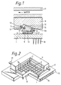
- a fluorine-containing lubricating thin film in accordance with the present invention on a heat conducting block, for example, by coating the surface of the heat conducting intermediate block disclosed in JP-A-63-250848 mentioned above and shown in Fig. 1 hereof with the lubricating thin film, wear debris is not produced even by the sliding between the block and the integrated circuit chip, thereby enabling the lubricating property to be maintained for a long period.
- a thin layer of thermally conductive grease is provided at the region of sliding contact.
- the grease improves thermal transfer between the contacting surfaces especially when one of the surfaces is curved.
- the grease has a thermal conductivity of at least 0.4 W/mK.
- This case of providing a fluorine-containing lubricant and a heat transfer grease is particularly preferred when the substrate carrying the lubricant is of metal. This solves a problem in the prior art. More specifically, although the metal surface generally corrodes when the water content and the additive in the heat transfer grease comes into contact with the metal surface, since the surface is coated with the fluorine-containing lubricant in the present invention, corrosion is reduced or avoided on the metal surface. Consequently, the thermal conduction remains high.
- the surface to which the thin film comprising fluorine-containing lubricant is bonded may be metal or ceramic. Electrically insulating ceramic materials are preferable, because being insulating a chipping from them is less likely to affect the semiconductor element. Preferred ceramics are AlN, SiC and Si3N4. Preferred metals are copper and copper alloys.
- advantages obtainable with the present invention are the reduction of wear at the sliding surfaces, combined with good thermal transfer. Particularly, the heat conduction is not reduced by wear. Another advantage is the avoidance of corrosion by grease, when grease is used. The reduction of friction obtained leads to better fitting of the surfaces to each other, so that heat flow is better, and a lower force is required to maintain contact of the sliding surfaces. The use of a lower force is in itself advantageous, since it reduces wear yet further and reduces the risk of damage to a sensitive semiconductor element.
- Fig. 1 shows part of a semiconductor module composed of a wiring substrate 1, a plurality of semiconductor elements 2 mounted on the substrate 1, only one element 2 being shown in Fig. 1, and a heat conducting intermediate block 3 of aluminium nitride, which has a high heat conductivity.
- the element 2 is connected to the substrate 1 by a plurality of solder connecting members 4.
- the block 3 is movable and makes sliding contact with the rear surface of the element 2.
- the block 3 is movably connected to a fixed heat transfer block 6 by a spring member 5.
- the block 3 also slidably contacts the heat transfer block 6, which itself is disposed in thermal contact with a coolant body 7 containing a water coolant passage.
- the blocks 3 and 6 may be of metal or ceramic. Suitable materials are given above and in the Examples.
- Electric signals and power which are input to the substrate 1 through pins 8 are supplied to the semiconductor element 2 through the connecting members 4.
- the semiconductor element 2 is highly integrated so as to increase its computing speed, and since a large amount of current is supplied to a very small area, a large amount of heat is generated by the semiconductor element.
- the heat conducting intermediate block 3 is a trigonal prism with the flat bottom surface 9 and with a cylindrically curved upper surface 10.
- Other curvatures than cylindrical may be used.
- the curvature is in one direction, which means the same as the curvature is in one plane, i.e. the curved surface can be defined by moving a curve which lies in a single plane perpendicularly to that plane.
- a recess 11 is provided in the other inclined surface and the spring 5 is located in the recess 11. At the opposite end of this spring 5, the transfer heat block 6 has a similar recess 12.
- the large amount of heat generated from the semiconductor elements 2 is transferred from the bottom surface 9 of the block 3 which is in contact with the rear side of the semiconductor element 2.
- the block 3 may be surrounded by a gas having a high heat conductivity, e.g. helium gas, for the purpose of good heat transfer.
- the block 6 is provided with a V-shaped groove having a shape similar to that of the block 3.
- One surface of the V-shaped groove is a flat surface 6a with which the curved upper surface 10 of the block 3 comes into sliding contact.
- the heat transferred to the intermediate block 3 is transferred from the upper surface 10 to the flat surface 6a of the V-shaped groove.
- the gas having a high heat conductivity assists good heat transfer at this region also.
- the coolant body 7 is disposed on the upper surface of the heat transfer block 6. Coolant for releasing the heat generated from the elements 2 to the outside of the system flows in the coolant unit 7. Heat transfer occurs via the contact of the bottom surface of the coolant unit 7 and the upper surface of the heat transfer block 6.
- Fig. 2 shows the cooling system of Fig. 1 applied to a semiconductor module having a large number of the elements 2 which are typically semiconductor chips.
- the elements 2 are mounted in common on the wiring substrate 1, and the pins 8 project into holes 14 in a support board 15 in conventional manner.
- the body 7 On the substrate 1 is also mounted the body 7 providing a housing which, with the substrate 1, hermetically encloses the elements 2 and the heat transfer blocks 3.
- the cooling water passages in the housing body 7 are indicated at 16.
- the housing body 7 may be in several parts sealed together and with appropriate thermal contact ensured.
- a cooling water inlet and outlet 17 are indicated. Warm water may be used, to avoid condensation.
- the heights and inclinations of the elements 2 vary among the elements 2 due to the non-uniformity in the production of the substrate 1, the attachment of the connecting members 4, etc.
- the heat conducting intermediate block 3 flexibly moves so as to achieve in each case face contact between the upper surface of the element 2 and the intermediate block 3 and the line contact between the bottom surface 6a of the heat transfer block 6 and the curved surface 10 of the intermediate block 3, thereby realizing good heat transfer, even though there is non-uniformity in the height and inclination of the semiconductor element 2.
- the intermediate block 3 can move under the action of the spring 5 parallel to the upper rear surface of the element 2 and perpendicularly to the axis of curvature of the curved surface 10 of the intermediate block 3. In other words, when the gap between the element 2 and the heat transfer block 6 becomes large, the intermediate block 3 moves along the element 2, thereby compensating for the non-uniformity in height.
- the intermediate block 3 rotates. It can rotate about the axis of curvature of the curved surface 10, and about an axis perpendicular to the rear face 9 of the element 2.
- the line contact of the curved surface 10 of the intermediate block 3 and the bottom surface of the block 6 is maintained.
- the block 3 has thin films 13 comprising fluorine-containing lubricant fixed on its opposite surfaces 9,10. These films 13 have been described generally above and will be illustrated below.
- the surface 6a of the block 6 may carry a similar surface.
- the opposite surfaces of the intermediate block 3 contacting the semiconductor element 2 and the block 6 are considered to be at an angle ⁇ , since in practice the curvature of the surface 40 is small.
- the angle ⁇ is an important factor in determining the heat transfer characteristics and the movement characteristics of the intermediate block 3. The larger the angle ⁇ , the more the heat transfer area (the contact area between the intermediate block 3 and the heat transfer block 6) increases, but the more the gap between the heat transfer block 6 and the semiconductor element 2 disadvantageously enlarges.
- the first term on the right-hand side represents a thermal resistance at the contacting surface and the second term the thermal resistance of the intermediate block 3.
- the optimum angle is selected on the basis of the thermal conductivity of the intermediate block 3, the heat transfer coefficient at the contacting surface, etc. obtained from the above equation.
- Fig. 3 shows the influence of the change of height of the substrate 1 due to heat or the like on the thermal resistance.
- the solid line indicates the calculated value and the plotted points indicate the measured values.
- Fig. 4 shows the change of thermal resistance with the inclination of the semiconductor element 2 due to warping or the like which is caused by heat.
- Fig. 3 shows that the line contact is adequately maintained even if the height of the substrate of the elements 2 changes by about 1 mm and that the thermal resistance is constant. If the angle of inclination of the semiconductor element 2 is about 1 degree, the line contact is adequately maintained, and the thermal resistance is constant, thereby producing no problem in practical use.
- the cooling structure of this invention has a high reliability.
- Heat conducting intermediate blocks 3 of aluminium nitride of the cooling system of Fig. 1 were washed by an ultrasonic cleaner filled with a trifluorotrichloroethane solution, and thoroughly dried after washing.
- the thus-prepared intermediate blocks 3 were dipped in trifluorotrichloroethane solutions containing 0.2 wt% of various fluorine lubricants each having a silanol group at one end of its molecule, as shown in Table 1 dissolved therein so as to coat the surface of the intermediate block 3 in each case with the respective fluorine lubricant, and thereafter heat-treated at 120°C for 5 minutes.
- the intermediate block 3 was then washed by an ultrasonic cleaner filled with a trifluorotrichloroethane solution so as to remove the surplus fluorine lubricant.
- the thickness of the completed film was about 5 nm.
- the lubricating property of the thus-obtained intermediate blocks 3 was evaluated by a dust producing test which measures the amount of dust produced during minute sliding.
- the dust testing apparatus is schematically shown in Fig. 5.
- the resultant wear debris 24 produced was collected by a silicon wafer 23 placed under the slightly reciprocating disk 21.
- the amount of wear debris on the silicon wafer, namely, the amount of dust produced was measured by a laser surface inspecting device (produced by Hitachi, Ltd. Type: HLD-300b) together with the particle diameter of the dust.
- each block 3 was measured by incorporating the block 3 with its surface treated with a lubricant into a cooling structure.
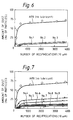
- Fig. 6 The results of the dust producing test are shown in Fig. 6. From Fig. 6, it is observed that the amount of dust produced by the intermediate blocks 3 with the surface treated with the fluorine lubricant having a silanol at the end was very small at the initial state as compared with the material without lubrication treatment, and that the lubricating property was improved to a great extent. From the results of the measurements of the thermal resistance shown in Table 2, it is observed that the thermal resistance was scarcely increased with the lubrication treatment, which was proved to be an excellent surface treatment.
- Heat conducting intermediate blocks 3 of AlN for the cooling system of Fig. 1 were washed by an ultrasonic cleaner filled with a trifluorotrichloroethane solution, and thoroughly dried after washing. Each was then given a different lubricant film, as follows.
- Solution 1 was prepared by dissolving 4.8 g of an epoxy resin EP1004 (trade name: produced by Du Pont), 0.88 g of a phenol resin Hitanol 1501 (trade name: produced by Hitachi Chemical Company, Ltd.) and a hardening accelerator, 0.06g of triethylammonium carbonate TEA-KI (trade name: produced by Hokko Chemical Industrial Co., Ltd.) into 200 g of methyl ethyl ketone.
- Solution 2 was prepared in each case by dissolving a solution of 0.56 g of a fluorine compound shown in Table 3 in 10 g of methyl ethyl ketone into Solution 1.
- the intermediate block 3 washed as described was dipped in the thus-prepared solution 2, taken out of the solution and heat-treated at 230°C for 60 minutes.
- the block 3 was then washed by an ultrasonic cleaner filled with a trifluorotrichloroethane solution.
- the resultant lubricant film consisted of a binder or support layer 20 nm thick and a thin upper layer 4 nm thick of the fluorine-containing lubricant anchored to the binder layer.
- the lubricating property of the thus-obtained block 3 was evaluated by the dust producing test in the same way as in Example 1 and the thermal resistance thereof incorporated into the cooling structure was also measured.
- Example 1 As comparison, the same heat conducting intermediate block 3 without lubrication treatment was used, as in Example 1.
- Fig. 7 The results of the dust producing test are shown in Fig. 7. From Fig. 7, it is observed that the amount of dust produced by the blocks 3 with the treated surface was very small at the initial stage as compared with the material without lubrication treatment, and that the lubricating property was improved to a great extent. From the results of the measurements of the thermal resistance shown in Table 4, it is observed that the thermal resistance was scarcely increased with the lubrication treatment, which was thus proved to be an excellent surface treatment.
- Heat conducting intermediate blocks 3 of a cooling system of Fig. 1 were produced from pure copper, washed by an ultrasonic cleaner filled with a trifluorotrichloroethane solution, and thoroughly dried after washing.
- the washed and dried block 3 of pure copper in each case was dipped in the solution 2, taken out of the solution and heat-treated at 230°C for 60 minutes.
- the block 3 was then washed by an ultrasonic cleaner filled with a trifluorotrichloroethane solution.
- the thickness of the completed lubricant layer was about 25 nm.
- the lubricating property of the thus-obtained block 3 of pure copper was measured by incorporating it into the cooling structure and heat transfer grease YG6240S (trade name: produced by Toshiba Silicon, Ltd, thermal conductivity 0.84 W/mK) was provided at the contact region between the block 3 and the element 2 (LSI device), and at the contact region between the block 3 and the heat transfer block 6.
- the thermal resistance of the resultant cooling structure and the state of corrosion of the block 3 of pure copper were observed.
- the corrosion state was judged by observing whether or not there was a change in the color of the surface of the block 3 of pure copper.
- Heat conducting intermediate blocks 3 of AlN for the cooling system of Fig. 1 were washed by an ultrasonic cleaner filled with a trifluorotrichloroethane solution and thoroughly dried after washing.
- the blocks 3 were then dipped in trifluorotrichloroethane solutions containing in each case 0.2 wt% of fluorine-lubricant having a silanol end group as shown in Table 1 dissolved therein so as to coat the surface thereof, and thereafter heat-treated at 120°C for 5 minutes.
- the block 3 was then washed by an ultrasonic cleaner filled with a trifluorotrichloroethane solution so as to remove the surplus fluorine lubricant.
- the thickness of the completed film was about 5 nm.
- the intermediate block 3 so obtained was incorporated into the cooling structure and heat transfer grease (trade name: YG6240S, product of Toshiba Silicon, Ltd.) was provided at the contact region between the heat conducting intermediate block 3 and the element 2 (LSI chip) and at the contact region with the heat transfer block 6.
- heat transfer grease (trade name: YG6240S, product of Toshiba Silicon, Ltd.) was provided at the contact region between the heat conducting intermediate block 3 and the element 2 (LSI chip) and at the contact region with the heat transfer block 6.
- the thermal resistance of the heat conducting intermediate block thus incorporated in the cooling structure was measured.
- Example 7 As comparison, the same heat conducting intermediate block without lubricating treatment, was used as in Example 1. The results of the heat resistance measurement indicate that the heat resistance is small and the surface treatment is excellent as shown in Table 7.
- Heat conducting intermediate blocks 3 of pure copper were used, and as in Example 4 a fluorine lubricant layer having a silanol end group was formed on each block 3.
- Each block 3 was then incorporated into the cooling structure of Fig. 1 and heat transfer grease (trade name: YG6240S, product of Toshiba Silicon, Ltd.) was provided at the contact regtion between the heat conducting intermediate block 3 and the element 2 (LSI chip) and at the contact region with the heat transfer block 6.
- the thermal resistance of the cooling structure and the state of surface corrosion of the heat conducting intermediate block 3 of pure copper were observed. The corrosion state was judged by observing whether or not there was a change in the colour of the surface of the block 3 of pure copper.
- Example 2 In the same manner as in Example 2, a fixed lubricant film of binder layer having a thickness of 20 nm and a lubricant layer having a thickness of about 4 nm were formed on heat conducting intermediate blocks 3 of AlN. Each block 3 was then incorporated into the cooling structure of Fig. 1 and heat transfer grease (trade name: YG6240S, product of Toshiba Silicon, Ltd.) was provided on the contact surface between the block 3 and the element 2 (LSI chip) and on the contact surfaces with the heat transfer block 6. The thermal resistance of the block 3 thus incorporated in the cooling structure was measured.
- heat transfer grease trade name: YG6240S, product of Toshiba Silicon, Ltd.
Landscapes
- Chemical & Material Sciences (AREA)
- Chemical Kinetics & Catalysis (AREA)
- General Chemical & Material Sciences (AREA)
- Oil, Petroleum & Natural Gas (AREA)
- Organic Chemistry (AREA)
- Cooling Or The Like Of Semiconductors Or Solid State Devices (AREA)
Claims (21)
- Système de refroidissement pour refroidir un élément semi-conducteur (2) comprenant un puits thermique (6, 7) et une voie de circulation de la chaleur pour dissi-per la chaleur dudit élément vers ledit puits thermique, ladite voie de circulation de la chaleur comprenant deux surfaces espacées opposées, une desdites surface étant en liaison thermique avec ledit puits thermique, l'autre surface étant en liaison thermique avec ledit élément semi-conducteur, et un élément thermiquement conducteur (3) interposé entre lesdites deux surfaces espacées (6a) pour conduire la chaleur entre lesdites deux surfaces et pouvant glisser par rapport à au moins une desdites surfaces espacées dans une région de contact glissant, caractérisé en ce que dans ladite région de contact glissant, au moins l'un dudit élément thermiquement conducteur (3) et de ladite surface (6a) ainsi en contact, porte un film mince (13) comprenant un lubrifiant contenant du fluor fixé à celui-ci.
- Système de refroidissement selon la revendication 1, dans lequel ledit film mince (13) présente une épaisseur ne dépassant pas 5 µm.
- Système de refroidissement selon la revendication 2, dans lequel ledit film mince (13) présente une épaisseur dans l'intervalle de 2 nm à 100 nm.
- Système de refroidissement selon l'une quelconque des revendications 1 à 3, dans lequel ledit lubrifiant contenant du fluor est chimiquement lié à la surface qui le porte.
- Système de refroidissement selon la revendication 4, dans lequel ladite liaison chimique est assurée par une liaison de type silanol.
- Système de refroidissement selon la revendication 4 ou 5, dans lequel l'épaisseur dudit film (13) varie dans l'intervalle de 2 nm à 10 nm.
- Système de refroidissement selon la revendication 4, dans lequel ledit composé contenant du fluor est représenté par la formule générale suivante :

- Système de refroidissement selon l'une quelconque des revendications 1 à 3, dans lequel ledit film mince (13) comprend ledit lubrifiant contenant du fluor et une couche support pour celui-ci, fixée à la surface portant ledit film mince, des molécules dudit lubrifiant étant ancrées à ladite couche support.
- Système de refroidissement selon la revendication 8, dans lequel ladite couche est une couche de résine durcie.
- Système de refroidissement selon la revendication 8 ou 9, dans lequel ledit composé contenant du fluor est représenté par la formule générale suivante :

- Système de refroidissement selon la revendication 8 ou 9, dans lequel ledit composé contenant du fluor est représenté par la formule générale suivante :

- Système de refroidissement selon l'une quelconque des revendications 8 à 11, dans lequel ledit lubrifiant contenant du fluor présente une structure moléculaire comprenant une première partie ayant une chaîne fluoropolyéther et une seconde partie ayant une plus grande affinité avec ladite couche support que ladite première partie, ladite seconde partie étant ancrée à ladite couche support.
- Système de refroidissement selon l'une quelconque des revendications précédentes, dans lequel ledit film (13) est sur ledit élément thermiquement conducteur (3).
- Système de refroidissement selon l'une quelconque des revendications précédentes, dans lequel une couche de graisse thermiquement conductrice est placée entre ledit élément thermiquement conducteur et ladite surface à son contact.
- Système de refroidissement selon la revendication 14, dans lequel ladite graisse présente une conductivité thermique d'au moins 0,4 W/mK.
- Système de refroidissement selon l'une quelconque des revendications 1 à 15, dans lequel ledit élément thermiquement conducteur (3) et ladite surface espacée (6a) ainsi en contact sont en contact linéaire l'un avec l'autre, et ledit système a en outre un ressort (5) poussant ledit élément thermiquement conducteur au contact de ladite surface espacée ainsi en contact.
- Système de refroidissement selon l'une quelconque des revendications 1 à 16, dans lequel au moins l'un dudit élément thermiquement conducteur (3) et de ladite surface espacée (6a) ainsi en contact est en métal.
- Appareil comprenant au moins un dispositif semi-conducteur (2), un passage de produit réfrigérant (16) pour le produit réfrigérant destiné à refroidir ledit dispositif semi-conducteur et une structure de refroidissement selon l'une quelconque des revendications 1 à 17 fournissant une voie de circulation de la chaleur dudit dispositif semi-conducteur audit passage de produit réfrigérant.
- Module à semi-conducteurs comprenant plusi-eurs dispositifs semiconducteurs (2) montés sur un support commun (1) et un corps réfrigérant (7) pour lesdits dispositifs , comprenant au moins un passage de circulation (16) pour le produit réfrigérant, et pour chacun desdits éléments semi-conducteurs, un système de refroidissement selon la revendication 1, fournissant une voie de circulation de la chaleur dudit dispositif semi-conducteur audit passage de produit réfrigérant.
- Elément thermiquement conducteur destiné à être utilisé dans un système de refroidissement pour un dispositif semi-conducteur selon la revendication 1, comprenant un corps (3) ayant sur ses côtés opposés une première surface qui est plane et une seconde surface qui est incurvée dans un seul sens, caractérisé en ce qu'au moins une desdites surfaces porte un film mince (13) comprenant un lubrifiant contenant du fluor fixé audit élément.
- Elément thermiquement conducteur selon la revendication 20, dans lequel ledit film mince (13) est sur ladite surface incurvée.
Applications Claiming Priority (2)
| Application Number | Priority Date | Filing Date | Title |
|---|---|---|---|
| JP1211358A JPH0612794B2 (ja) | 1989-08-18 | 1989-08-18 | 半導体実装モジユール及び冷却構造体 |
| JP211358/89 | 1989-08-18 |
Publications (2)
| Publication Number | Publication Date |
|---|---|
| EP0413565A1 EP0413565A1 (fr) | 1991-02-20 |
| EP0413565B1 true EP0413565B1 (fr) | 1995-10-25 |
Family
ID=16604648
Family Applications (1)
| Application Number | Title | Priority Date | Filing Date |
|---|---|---|---|
| EP90308941A Expired - Lifetime EP0413565B1 (fr) | 1989-08-18 | 1990-08-14 | Système de refroidissement pour un dispositif semi-conducteur, module semi-conducteur ayant un tel système et utilisant un corps de refroidissement thermoconducteur |
Country Status (5)
| Country | Link |
|---|---|
| EP (1) | EP0413565B1 (fr) |
| JP (1) | JPH0612794B2 (fr) |
| AU (1) | AU6101690A (fr) |
| CA (1) | CA2023359A1 (fr) |
| DE (1) | DE69023188T2 (fr) |
Cited By (1)
| Publication number | Priority date | Publication date | Assignee | Title |
|---|---|---|---|---|
| US20180098462A1 (en) * | 2015-04-24 | 2018-04-05 | Nec Corporation | Heat dissipation mechanism and device including the same |
Families Citing this family (2)
| Publication number | Priority date | Publication date | Assignee | Title |
|---|---|---|---|---|
| JP2599064B2 (ja) * | 1992-01-28 | 1997-04-09 | アトムメディカル株式会社 | 検診台の制御装置 |
| JP6981637B2 (ja) * | 2017-02-06 | 2021-12-15 | 日本電気株式会社 | 熱伝導装置および電子部品 |
Family Cites Families (1)
| Publication number | Priority date | Publication date | Assignee | Title |
|---|---|---|---|---|
| JPH063831B2 (ja) * | 1987-04-08 | 1994-01-12 | 株式会社日立製作所 | 冷却装置及びそれを用いた半導体装置 |
-
1989
- 1989-08-18 JP JP1211358A patent/JPH0612794B2/ja not_active Expired - Lifetime
-
1990
- 1990-08-14 EP EP90308941A patent/EP0413565B1/fr not_active Expired - Lifetime
- 1990-08-14 DE DE69023188T patent/DE69023188T2/de not_active Expired - Fee Related
- 1990-08-15 CA CA002023359A patent/CA2023359A1/fr not_active Abandoned
- 1990-08-15 AU AU61016/90A patent/AU6101690A/en not_active Abandoned
Cited By (1)
| Publication number | Priority date | Publication date | Assignee | Title |
|---|---|---|---|---|
| US20180098462A1 (en) * | 2015-04-24 | 2018-04-05 | Nec Corporation | Heat dissipation mechanism and device including the same |
Also Published As
| Publication number | Publication date |
|---|---|
| DE69023188T2 (de) | 1997-11-27 |
| CA2023359A1 (fr) | 1991-02-19 |
| EP0413565A1 (fr) | 1991-02-20 |
| JPH0612794B2 (ja) | 1994-02-16 |
| AU6101690A (en) | 1991-03-28 |
| DE69023188D1 (de) | 1995-11-30 |
| JPH0376147A (ja) | 1991-04-02 |
Similar Documents
| Publication | Publication Date | Title |
|---|---|---|
| Prasher et al. | Thermal contact resistance of cured gel polymeric thermal interface material | |
| Gwinn et al. | Performance and testing of thermal interface materials | |
| US4908695A (en) | Cooling apparatus and semiconductor device employing the same | |
| Yovanovich et al. | Calculating interface resistance | |
| US7057891B2 (en) | Heat dissipation structure | |
| JPS60126853A (ja) | 半導体デバイス冷却装置 | |
| Smalc et al. | Thermal performance of natural graphite heat spreaders | |
| US5195020A (en) | Cooling system used with an electronic circuit device for cooling circuit components included therein having a thermally conductive compound layer and method for forming the layer | |
| Ohsone et al. | Optical measurement of thermal contact conductance between wafer-like thin solid samples | |
| EP0219674B1 (fr) | Dispositif de refroidissement pour composants électroniques | |
| EP0413565B1 (fr) | Système de refroidissement pour un dispositif semi-conducteur, module semi-conducteur ayant un tel système et utilisant un corps de refroidissement thermoconducteur | |
| Azar et al. | Effect of pin fin density of the thermal performance of unshrouded pin fin heat sinks | |
| He et al. | Direct measurement and analysis of the time-dependent evolution of stress in silicon devices and solder interconnections in power assemblies | |
| Dai et al. | Thermo-mechanical deformation of underfilled flip-chip packaging | |
| JPS59130450A (ja) | Icパツケ−ジの冷却構造 | |
| Chen et al. | Effect of material interactions during thermal shock testing on IC package reliability | |
| Guo et al. | A practical die stress model and its applications in flip-chip packages | |
| Kwon et al. | The effect of T/sub g/on thermo-mechanical deformation and reliability of adhesive flip chip assemblies during temperature cycling | |
| JPS58199546A (ja) | 半導体冷却装置 | |
| Min et al. | TIM characterization for high performance microprocessors | |
| JPH01187840A (ja) | 半導体装置 | |
| Han | Characterization of stresses and strains in microelectronics and photonics devices using photomechanics methods | |
| Chen et al. | Thermal characterization of thermal interface materials | |
| Toh et al. | Thermal contact conductance of typical interfaces in electronic packages under low contact pressures | |
| JPH04183790A (ja) | 含フッ素系表面改質材、それを用いた伝熱部材および半導体実装モジュール |
Legal Events
| Date | Code | Title | Description |
|---|---|---|---|
| PUAI | Public reference made under article 153(3) epc to a published international application that has entered the european phase |
Free format text: ORIGINAL CODE: 0009012 |
|
| 17P | Request for examination filed |
Effective date: 19901010 |
|
| AK | Designated contracting states |
Kind code of ref document: A1 Designated state(s): DE FR GB NL |
|
| 17Q | First examination report despatched |
Effective date: 19930713 |
|
| GRAA | (expected) grant |
Free format text: ORIGINAL CODE: 0009210 |
|
| AK | Designated contracting states |
Kind code of ref document: B1 Designated state(s): DE FR GB NL |
|
| REF | Corresponds to: |
Ref document number: 69023188 Country of ref document: DE Date of ref document: 19951130 |
|
| ET | Fr: translation filed | ||
| PGFP | Annual fee paid to national office [announced via postgrant information from national office to epo] |
Ref country code: GB Payment date: 19960802 Year of fee payment: 7 |
|
| PGFP | Annual fee paid to national office [announced via postgrant information from national office to epo] |
Ref country code: FR Payment date: 19960814 Year of fee payment: 7 |
|
| PLBE | No opposition filed within time limit |
Free format text: ORIGINAL CODE: 0009261 |
|
| STAA | Information on the status of an ep patent application or granted ep patent |
Free format text: STATUS: NO OPPOSITION FILED WITHIN TIME LIMIT |
|
| 26N | No opposition filed | ||
| PG25 | Lapsed in a contracting state [announced via postgrant information from national office to epo] |
Ref country code: GB Free format text: LAPSE BECAUSE OF NON-PAYMENT OF DUE FEES Effective date: 19970814 |
|
| PG25 | Lapsed in a contracting state [announced via postgrant information from national office to epo] |
Ref country code: DE Free format text: LAPSE BECAUSE OF NON-PAYMENT OF DUE FEES Effective date: 19980303 |
|
| GBPC | Gb: european patent ceased through non-payment of renewal fee |
Effective date: 19970814 |
|
| PG25 | Lapsed in a contracting state [announced via postgrant information from national office to epo] |
Ref country code: FR Free format text: LAPSE BECAUSE OF NON-PAYMENT OF DUE FEES Effective date: 19980430 |
|
| REG | Reference to a national code |
Ref country code: FR Ref legal event code: ST |
|
| PGFP | Annual fee paid to national office [announced via postgrant information from national office to epo] |
Ref country code: NL Payment date: 20010831 Year of fee payment: 12 |
|
| PG25 | Lapsed in a contracting state [announced via postgrant information from national office to epo] |
Ref country code: NL Free format text: LAPSE BECAUSE OF NON-PAYMENT OF DUE FEES Effective date: 20030301 |
|
| NLV4 | Nl: lapsed or anulled due to non-payment of the annual fee |
Effective date: 20030301 |