EP0413640A1 - Mess- und Berechnungseinrichtung mikrometeorologischer und bioklimatologischer Parameter - Google Patents
Mess- und Berechnungseinrichtung mikrometeorologischer und bioklimatologischer Parameter Download PDFInfo
- Publication number
- EP0413640A1 EP0413640A1 EP90402310A EP90402310A EP0413640A1 EP 0413640 A1 EP0413640 A1 EP 0413640A1 EP 90402310 A EP90402310 A EP 90402310A EP 90402310 A EP90402310 A EP 90402310A EP 0413640 A1 EP0413640 A1 EP 0413640A1
- Authority
- EP
- European Patent Office
- Prior art keywords
- air
- psychrometer
- box
- installation according
- installation
- Prior art date
- Legal status (The legal status is an assumption and is not a legal conclusion. Google has not performed a legal analysis and makes no representation as to the accuracy of the status listed.)
- Withdrawn
Links
Images


Classifications
-
- G—PHYSICS
- G01—MEASURING; TESTING
- G01W—METEOROLOGY
- G01W1/00—Meteorology
- G01W1/02—Instruments for indicating weather conditions by measuring two or more variables, e.g. humidity, pressure, temperature, cloud cover or wind speed
Definitions
- the subject of the present invention is an installation for measuring and calculating micrometeorological and bioclimatological parameters.
- the purpose of the installation according to the invention is to establish, on the basis of micrometeorological measurements, a balance of water and carbon dioxide energy exchanges between the atmosphere, the soil and a plant cover and more particularly to calculate evapotranspiration. real.
- Such installations are known from the prior art and include various sensors such as anemometers, wind vanes, psychrometer solar collectors, thermoprobes, fluxmeters, rain gauges and probes for temperatures of the ground, the surface of the ground and the air.
- sensors such as anemometers, wind vanes, psychrometer solar collectors, thermoprobes, fluxmeters, rain gauges and probes for temperatures of the ground, the surface of the ground and the air.
- these installations are equipped with an electronic unit for calculations and commands and with a unit for storing and managing the calculated values, these two units being arranged in a protective box placed near the gantry.
- a mobile carriage On the gantry of known installations, is mounted a mobile carriage on which are fixed at least two different levels of psychrometers measuring the humidity of the air. At each measurement level, at least one psychrometer is mounted, which increases the cost of such installations. In addition, these psychrometers are arranged outside and are therefore subject to weathering and direct solar radiation, which can lead to measurement errors but above all, their deterioration in the long run.
- the known installations therefore have several separate elements: the gantry, a mast carrying a balance meter, the box containing the calculation, control, storage and management units, the rain gauge and the various probes. All of these elements connected by cables and wires, has a large footprint and is long installation.
- the object of the present invention is to obviate the above-mentioned drawbacks by proposing a space-saving installation and easy installation, and offering good protection for some of these elements which need not necessarily be in direct contact with the outside to deliver measurements or the like.
- the installation of measurements and calculations of micrometeorological and bioclimatic parameters comprises at least one anemometer, at least one wind vane, at least one solar collector, at least one psychrommeter, at least one flow meter, at least one rain gauge, temperature sensors for the soil, the surface of the soil and the air, a control and calculation unit and a management and storage unit for the calculated values and is essentially characterized in that it comprises a box in which is arranged at least one psychrometer and at least one device for ducting outside air to the psychrometer.
- the external air duct device is provided with two external air inlets offset in height.
- the external air ducting device is disposed at the outlet of the box in an envelope in which an air circulation is created.
- the installation according to the invention comprises, in known manner, at least one anemometer 1, at least one wind vane 2, at least one solar collector 3, at least one psychrometer 4, at least one flow meter 5, one rain gauge 6, and soil temperature sensors, soil surface and air (not shown).
- this installation comprises a unit 7 for controlling the various sensors mentioned above and for calculating the data recorded by these sensors and a unit 8 for storing and managing the values calculated by the unit 7 for commands and calculations.
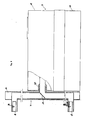
- the installation according to the invention comprises a box 9 consisting of a lower tank 10 and a cap 11 covering the tank and a mast 12 secured to the box 9 and arranged substantially vertically.
- a mast 12 secured to the box 9 and arranged substantially vertically.
- On the mast 12 are mounted by means of arms 13 fixed on either side of the said mast the anemometer (s) 1, the wind vane (s) 2, the solar collector (s) 3 and one or more temperature sensors of the 'air.
- the box 3 is arranged at least one psychrometer 4 and the installation is provided with at least one device 13 for ducting outside air to at least psychrometer 4.
- the units 7 for controlling and calculations and storage and management of calculated values.
- the installation preferably comprises a single rain gauge 6 which is also mounted on the box 9 with its measuring device placed inside said box.
- the rain gauge is associated with a rainwater analysis unit also placed in the box 9.
- Said box is formed of a lower tank 10 resting in separation from the ground on feet 14.
- This lower tank 10 has a bottom 10 A and walls 10 B perpendicular to the bottom 10 A and parallel two by two.
- the cap 11 of the box 9 has a flat upper wall 11A intended to be placed parallel above the bottom 10A of the lower tank 10 and side walls 11B parallel in pairs and perpendicular to the upper wall 11A.
- the side walls 11B of the cap 11 cover externally partly the side walls 10B of the lower tank 10.
- the side walls 11B each have a shoulder 11G against which the upper edges of the side walls 10B of the corresponding container 10 come into contact.
- the box is made of a material resistant to corrosion and solar radiation such as the material known under the trade name of "ABS".
- the command and calculation unit 7 and the unit 8 for storing and managing the calculated values are fixed to the bottom 10A of the lower tank 10 and at a spacing from said bottom.
- the device 6A for measuring the rainfall constituted in a known manner by a tilting bucket is fixed in spacing from the bottom 10A.
- this measuring device 6A can be fixed to a side wall 10B of the tank 10.
- the measuring device 6A can be associated with a device for the chemical analysis of rainwater.
- the bottom 10A of the lower tank 10 is provided longitudinally in the middle part of a channel 15 produced by a depression of the bottom 11A and has at least one slope.
- the channel 15 has two slopes which converge towards one another and is provided with an orifice 16 in the region of the line of convergence of its slopes.
- the bottom surfaces 10A converge towards the said channel.
- the shape of the bottom 10A of the tank 10 allows the recovery of the water in the channel 15 and their discharge through the orifice 16.
- a psychrometer 4 intended to measure the degree of hygronometry of the outside air and a device 13 for driving outside air to the said psychrometer.
- the psychrometer 4 is of known type and is equipped with its air suction fan 4A. This psychrometer is fixed in the box 9 above the units 7 and 8. The psychrometer 4 on its rear part is continued by a flexible pipe 17 rejecting the air sucked out of the box 9 through the orifice 16 of the lower tank 10.
- the front part of the psychrometer 4 is connected to the device 13 for driving the outside air.
- This air duct device 13 is constituted by a tube 18 provided with at least one inlet 19 arranged outside.
- the air duct device 13 of the installation according to the invention is provided with at least two air inlets 19 arranged outside in a height-offset manner so as to obtain an outside air intake at two different levels to perform differential measurement of dry and wet temperatures by the psychrometer 4.
- the air supply device has two air inlets 19.
- the tube 18 forming the air duct device 13 is connected inside the box 9 to the front part of the psychrometer 4 arranged horizontally in said box.
- the tube 18 opens out from the box 9 perpendicularly to the upper wall 11A of the cap and forms a bend between the psychrometer and its outlet from the box 9.
- the upper end of the tube 18 is bent so as to be disposed substantially horizontally and constitutes a first air inlet 19.
- a second air inlet 19 parallel to the first and preferably arranged on the same generator as said first air inlet.
- This second air inlet 19 can be produced by a sleeve connected to the tube 18 which is provided with an orifice for this purpose.
- the device 13 for ducting air to the psychrometer is provided inside the tube 18 with a tilting flap 20 disposed at the second air inlet 19 and intended to block the passage of air alternately. from the first air inlet 19 and allowing the passage of air from the second air inlet 19 and vice versa.
- This tilting flap 20 can be actuated by an electromagnet whose relay is controlled at a frequency determined by the control unit 7.
- the tube 18 of the air ducting device towards the psychrometer opens to the outside of the box 9 horizontally and perpendicularly to a wall 11A of the cap 11 of the box 9.
- the tube 18 according to this embodiment is divided at the outlet from the box into two coaxial branches arranged vertically and at the end of which the first and second air inlets 19 are formed.
- a tilting flap 20 In the tube 18 is mounted a tilting flap 20 at the division of said tube into two branches. This shutter is controlled alternately to carry out the air intake either on the first inlet or on the second inlet.
- the air inlets 19 of the tube 18 are arranged horizontally so as to directly receive an external air flow.
- the device 13 for supplying air to the psychrometer 4 is provided on each of its inputs 19 with a temperature probe 21 and is provided with another temperature probe 22 at the inlet to the psychrometer 4.
- a dry and wet temperature differential is established between the two air inlets 19 by the probes 21.
- the probe 22 at the inlet of the psychrometer 4 makes it possible to check the temperature of the air relative to that taken at the inlet 19 through which the air is supplied and to make corrections.
- the psychrometer 4 determines a humid temperature of the air at the level of the inlet 19 through which the air is taken.
- This wet temperature is measured alternately for one and the other input 19 as a function of the position of the tilting flap 20.
- the device 13 for conducting air to the psychrometer leaves the box 9 in order to be in direct contact with the outside and to undergo, among other things, direct radiation and therefore temperature variations.
- the contact of air with this device 13 can cause a phenomenon of condensation, which is completely undesirable since this air must be brought to the psychrometer which measures the hygronometric degree. It will therefore be understood that the condensation in the device 13 distorts the measurements made by the psychrometer 4.
- the latter is disposed at its outlet from the box 9 inside an envelope in which an air circulation is created.
- the casing makes it possible to protect the air duct device 13 from direct radiation and the air circulating in the casing and in contact with the duct device 13 is at the temperature of the outside air. In this way, no condensation phenomenon is created in the device 13 for conducting air to the psychrometer.
- the protective envelope preferably consists of the mast 12 of the installation which has a sufficient size to form around the device 13 an air circulation. According to the first embodiment shown in Figures 1 and 2 of the device 13 for air duct to the psychrometer 4 of the installation according to the invention, the mast 12 is mounted at its base inside the box 9 and emerges from the latter passing through an opening 23 formed in the upper wall 11A of the cap 11.
- the lower tank 10 of the box 9 is provided with a sheath 24 fixed on the bottom 10A and opposite which the opening 23 of the cap 11 is placed.
- the mast 12 is introduced through the opening 23 and is guided in the sheath 24 to rest on the bottom of the said sheath.
- the cap 11 can slide along the mast 12 which can advantageously be locked in position in the sleeve 24 by any known means such as a pressure screw.
- the mast 12 Inside the mast 12 is mounted the tube 18 of the device 13 for supplying air to the psychrometer 4.
- the mast 12 has, on one of its faces intended to be placed outside the box 9, orifices opposite which the air inlets 19 are placed.
- the tube 18 is fixed inside the mast at the air inlets 19.
- These air inlets are preferably formed by an attached sleeve which is fixed from the outside of the mast to the tube 18.
- Said tube at its end is provided with an elbow which attaches to the inner face of the mast, for example by means of a screwing sleeve.
- the sleeve forming the air inlet 19 is mounted on the tube 18 by fitting into the bent end of the latter. This sleeve is preferably removable.
- the tube is provided with a T, the leg of which is fixed to the inner face of the mast 12 and receives from the outside, by fitting, a sleeve constituting the second air inlet 19.
- the end of the tube connecting to the inlet of the psychrometer 4 can be fixed identically to its other end.
- the front part of the psychrometer is provided with a sliding sleeve which fits onto the tube 18 fixed inside the mast 12.
- the sheath 24 of the box 9 has an opening 24A and the mast 12 is provided with a light 12A placed opposite the opening 24A of the sleeve 24. The air circulation occurs naturally in the mast 12.
- the outside air intake is formed by the orifice 16 of the bottom 10A of the lower tank 10 and the air outlet on the mast is formed by the end open from said mast or by slots made at the end of its walls.
- the mast 12 is preferably of rectangular cross section and the sheath 24 of the same section as the mast is provided with a positioning element for the mast 12 so that the connection of the psychrometer 4 and the tube 18 is made.
- the air duct device 13 opens laterally from the box 9
- the mast 12 is mounted laterally to said box and extends vertically.
- the tube 18 is fixed by means of these air inlets 19.
- the mast is provided in the middle part of one of its walls with a connection mouth 30 to a wall of the box 9.
- the connection mouth 30 is of rectangular section and comes to lock in position in an opening 31 formed on a wall 11B of the upper tank 11.
- This mouth 30 is placed opposite the psychrometer 4 and contains the tube 18 connecting to said psychrometer.
- Said tube is preferably braced in the mouth 30 of the mast 12. This mouth 30 is therefore open and constitutes the entry inside the mast of the natural circulation of air.
- At the ends of the mast 12 are formed slots for the exhaust of air circulating inside the mast.
- the inlets 19 have a double wall.
- the temperature sensor 21 is attached to the interior wall of each air inlet. This double-walled formation makes it possible to protect the wall on which the temperature probe 21 is fixed from the sun.
- the installation according to the invention makes it possible, from a single psychrometer, to carry out a differential measurement of the dry and wet temperatures in order to calculate the actual evapotranspiration of the plant cover on which said installation is placed.
- this installation makes it possible to protect certain elements of the external environment and is of a reduced size and of an easy and fast installation.
- the installation as described can be equipped with a sensor for measuring atmospheric pressure, which allows this pressure value to be taken into account for the calculations of evapotranspiration, humidity and saturation deficit.
- This sensor will be located in the box and will be in communication with the outside of the box by a pipe passing through the orifice 16.
- upstream of the psychrometer can be arranged an interchangeable filter cartridge made of a material sufficiently porous to allow a correct flow of air through the psychrometer and dense enough to retain impurities which can subsequently be analyzed to determine the degree and the nature of air pollution.
- the air flow through the psychrometer can be controlled by an appropriate measuring device.
- the upper surface of the box into which the funnel of the rain gauge opens as well as its thickness can be calculated so that the rainwater which comes to strike this surface can by rebound be introduced partially or entirely into the funnel .
- This arrangement compensates for the lack of precision of the rain gauge in the event of heavy rain, this lack of precision being able to result from too low tilting speed of the buckets.
- the present invention can receive all arrangements and all variants in the field of technical equivalents without departing from the scope of this patent.
Landscapes
- Environmental & Geological Engineering (AREA)
- Engineering & Computer Science (AREA)
- Life Sciences & Earth Sciences (AREA)
- Atmospheric Sciences (AREA)
- Biodiversity & Conservation Biology (AREA)
- Ecology (AREA)
- Environmental Sciences (AREA)
- Testing Or Calibration Of Command Recording Devices (AREA)
Applications Claiming Priority (2)
| Application Number | Priority Date | Filing Date | Title |
|---|---|---|---|
| FR8911049A FR2651043B1 (fr) | 1989-08-18 | 1989-08-18 | Installation de mesures et de calculs de parametres micrometeorologiques et bioclimatologiques |
| FR8911049 | 1989-08-18 |
Publications (1)
| Publication Number | Publication Date |
|---|---|
| EP0413640A1 true EP0413640A1 (de) | 1991-02-20 |
Family
ID=9384807
Family Applications (1)
| Application Number | Title | Priority Date | Filing Date |
|---|---|---|---|
| EP90402310A Withdrawn EP0413640A1 (de) | 1989-08-18 | 1990-08-17 | Mess- und Berechnungseinrichtung mikrometeorologischer und bioklimatologischer Parameter |
Country Status (2)
| Country | Link |
|---|---|
| EP (1) | EP0413640A1 (de) |
| FR (1) | FR2651043B1 (de) |
Cited By (4)
| Publication number | Priority date | Publication date | Assignee | Title |
|---|---|---|---|---|
| GB2288246A (en) * | 1994-04-07 | 1995-10-11 | Helix Ltd | Meteorological apparatus |
| EP0859245A1 (de) * | 1997-02-14 | 1998-08-19 | Somfy | Kombinierter Wind- und Sonnenscheinmesser |
| RU2167439C2 (ru) * | 1999-05-31 | 2001-05-20 | Воронежский военный авиационный инженерный институт | Устройство для дистанционного определения водности облачной и безоблачной атмосферы |
| RU2167440C2 (ru) * | 1999-05-31 | 2001-05-20 | Воронежский военный авиационный инженерный институт | Способ дистанционного определения водности облачной и безоблачной атмосферы |
Citations (1)
| Publication number | Priority date | Publication date | Assignee | Title |
|---|---|---|---|---|
| FR2568372A1 (fr) * | 1984-07-27 | 1986-01-31 | Flambeau Sarl Indle Fse Meca | Installation de mesures et de calculs micrometeorologiques et bioclimatologiques |
-
1989
- 1989-08-18 FR FR8911049A patent/FR2651043B1/fr not_active Expired - Fee Related
-
1990
- 1990-08-17 EP EP90402310A patent/EP0413640A1/de not_active Withdrawn
Patent Citations (1)
| Publication number | Priority date | Publication date | Assignee | Title |
|---|---|---|---|---|
| FR2568372A1 (fr) * | 1984-07-27 | 1986-01-31 | Flambeau Sarl Indle Fse Meca | Installation de mesures et de calculs micrometeorologiques et bioclimatologiques |
Non-Patent Citations (1)
| Title |
|---|
| SIEMENS POWER ENGINEERING, vol. 11, no. 3, mars 1980, pages 72-74; L. JAEGER: "Process computers in microclimatology" * |
Cited By (5)
| Publication number | Priority date | Publication date | Assignee | Title |
|---|---|---|---|---|
| GB2288246A (en) * | 1994-04-07 | 1995-10-11 | Helix Ltd | Meteorological apparatus |
| EP0859245A1 (de) * | 1997-02-14 | 1998-08-19 | Somfy | Kombinierter Wind- und Sonnenscheinmesser |
| FR2759786A1 (fr) * | 1997-02-14 | 1998-08-21 | Somfy | Dispositif de mesure du vent et de l'ensoleillement |
| RU2167439C2 (ru) * | 1999-05-31 | 2001-05-20 | Воронежский военный авиационный инженерный институт | Устройство для дистанционного определения водности облачной и безоблачной атмосферы |
| RU2167440C2 (ru) * | 1999-05-31 | 2001-05-20 | Воронежский военный авиационный инженерный институт | Способ дистанционного определения водности облачной и безоблачной атмосферы |
Also Published As
| Publication number | Publication date |
|---|---|
| FR2651043A1 (fr) | 1991-02-22 |
| FR2651043B1 (fr) | 1991-12-06 |
Similar Documents
| Publication | Publication Date | Title |
|---|---|---|
| FR2514607A1 (fr) | Installation de mesure de l'evapotranspiration reelle d'un couvert vegetal, de mesure du taux de gaz carbonique echange entre ce couvert vegetal et l'atmosphere et de mesure de l'etat hydrique du sol du couvert vegetal | |
| EP1003991A1 (de) | Vorrichtung zur inspektion von lüftungs- oder klimarohren, und andere rohrleitungen | |
| EP1381873B1 (de) | Gesamtdruck-strömungsmessvorrichtung | |
| FR2651043A1 (fr) | Installation de mesures et de calculs de parametres micrometeorologiques et bioclimatologiques | |
| EP2691778B1 (de) | Vorrichtung zur instandhaltung und untersuchung einer aerodynamischen sonde | |
| FR2708347A1 (fr) | Chambre de mesure, notamment pour le contrôle de l'eau d'une piscine. | |
| EP1025366A1 (de) | Fluidischer oszillator mit verlängtem spalt | |
| EP0076759B1 (de) | Vorrichtung zur kontinuierlichen Bestimmung des Heizwertes von Gasen | |
| EP3607278B1 (de) | Fluidmesser | |
| EP0432002B1 (de) | Vorrichtung zur automatischen und fortlaufenden Ermittlung von Parametern, die das Zusammenwirken von Boden, Pflanzen und Klima kennzeichnen | |
| FR2531490A1 (fr) | Detecteur de temperature du flux d'air dans une turbomachine | |
| FR2748811A1 (fr) | Mesure de flux surfacique de gaz | |
| EP3190346B1 (de) | Relais-verbindungsvorrichtung für zwangsbelüftungsanlage, diese umfassendes relais-verbindungssystem und zwangsbelüftungsanlage, die mit diesen systemen ausgestattet ist | |
| FR2775783A1 (fr) | Procede et dispositif de mesure de pression a l'interieur d'un generateur de vapeur | |
| EP0685710B1 (de) | Anti-Beschlagvorrichtung für Flüssigkeitstotalmengenzähler | |
| EP2569623B1 (de) | System zur messung oder überwachung der qualität eines flüssigmediums mit geringem energieverbrauch | |
| FR2770306A1 (fr) | Pluviometre pour toutes conditions de precipitations | |
| EP0910808A1 (de) | Bioklimatologische messstation | |
| WO2017103402A1 (fr) | Système de collecte de poussières, procédé de détermination d'au moins une propriété d'un matériau en matière de dégagement de poussières, et procédé d'arrosage d'un sol | |
| FR3112606A1 (fr) | Système à rotor de mesure du débit d’un fluide comportant du liquide, et équipement associé | |
| EP4348276B1 (de) | Aerodynamische messsonde | |
| FR3003125A1 (fr) | Dispositif de surveillance pour l'entretien de plantes et systeme correspondant | |
| FR3026757A1 (fr) | Station de relevage d’eaux | |
| EP3662248B1 (de) | Vorrichtung zum sammeln und entnehmen von aerosolen | |
| EP1889527B1 (de) | Belüftungssystem |
Legal Events
| Date | Code | Title | Description |
|---|---|---|---|
| PUAI | Public reference made under article 153(3) epc to a published international application that has entered the european phase |
Free format text: ORIGINAL CODE: 0009012 |
|
| AK | Designated contracting states |
Kind code of ref document: A1 Designated state(s): AT BE CH DE DK ES FR GB GR IT LI LU NL SE |
|
| 17P | Request for examination filed |
Effective date: 19910816 |
|
| 17Q | First examination report despatched |
Effective date: 19930506 |
|
| RAP1 | Party data changed (applicant data changed or rights of an application transferred) |
Owner name: I.F.M.E. FLAMBEAU SARL Owner name: ELECTRONIC PUBLISHING INTERNATIONAL (BERMUDA) LIM |
|
| STAA | Information on the status of an ep patent application or granted ep patent |
Free format text: STATUS: THE APPLICATION IS DEEMED TO BE WITHDRAWN |
|
| 18D | Application deemed to be withdrawn |
Effective date: 19951205 |