EP0413669A2 - Antriebsvorrichtung - Google Patents
Antriebsvorrichtung Download PDFInfo
- Publication number
- EP0413669A2 EP0413669A2 EP90850275A EP90850275A EP0413669A2 EP 0413669 A2 EP0413669 A2 EP 0413669A2 EP 90850275 A EP90850275 A EP 90850275A EP 90850275 A EP90850275 A EP 90850275A EP 0413669 A2 EP0413669 A2 EP 0413669A2
- Authority
- EP
- European Patent Office
- Prior art keywords
- frame
- drive wheel
- implements
- pivotal
- wheel
- Prior art date
- Legal status (The legal status is an assumption and is not a legal conclusion. Google has not performed a legal analysis and makes no representation as to the accuracy of the status listed.)
- Granted
Links
Images

Classifications
-
- A—HUMAN NECESSITIES
- A01—AGRICULTURE; FORESTRY; ANIMAL HUSBANDRY; HUNTING; TRAPPING; FISHING
- A01B—SOIL WORKING IN AGRICULTURE OR FORESTRY; PARTS, DETAILS, OR ACCESSORIES OF AGRICULTURAL MACHINES OR IMPLEMENTS, IN GENERAL
- A01B51/00—Undercarriages specially adapted for mounting on various kinds of agricultural tools or apparatus
- A01B51/02—Undercarriages specially adapted for mounting on various kinds of agricultural tools or apparatus propelled by a motor
- A01B51/026—Undercarriages specially adapted for mounting on various kinds of agricultural tools or apparatus propelled by a motor of the automotive vehicle type, e.g. including driver accommodation
Definitions
- the present invention relates to an apparatus for displacement or advancement of implements, for example ball collectors (so-called ball harvesters), lawnmowers, etc.
- implements for example ball collectors (so-called ball harvesters), lawnmowers, etc.
- the object forming the basis of the present invention is to obviate or at least reduce the drawbacks inherent in prior art apparatuses of the type contemplated herein and to satisfy the established desiderata.
- a forward beam is provided with at least two pivotal wheels disposed in spaced-apart relationship, and with coupling means for coupling of a number of implements; and that the beam is connected to a frame which is provided with at least one steerable drive wheel spaced at such a distance from the beam that the number of implements will have room between the frame and the steerable drive wheel, and which extends freely over the number of implements.
- the beam is pivotally connected to the frame in such a manner that the beam and the frame are pivotal in relation to one another about a horizontal axis.
- the pivotal wheels on the beam are freely rotatable, in the manner of castors or swivels.
- the drive wheel is journalled in a generally U-shaped bracket which is pivotal in the frame.
- the drive wheel is connected to a hydraulic motor.
- the hydraulic motor is placed in the hub of the drive wheel.
- the drive wheel is of considerably larger diameter than the pivotal wheels on the beam, whereby the frame slopes from the drive wheel towards the frame.
- a seat and a steering arrangement are disposed on the frame. The steering arrangement is disposed, by turning of a steering wheel in one direction in which the number - or cluster - of implements is to be displaced or advanced, to realise a drive wheel response throw in the opposite direction.
- the present invention realises a displacement or advancement apparatus of an extremely simple and uncomplicated design and construction which, moreover, will permit advancement or displacement of implements disposed thereon in a highly efficient and gentle manner. Since the advancement force and requisite pivotal force act in substantially the same direction, a very small turning radius will be achieved and, above all, relatively slight forces will act on the implements and the various parts of the apparatus. To a considerable extent, this feature makes possible the simple design and construction of the apparatus. Since the implement or implements may be placed between the forward support wheels and the rear drive wheel, the peripheral speed of the implement or implements will be greatly reduced in different turning radii, which is often of considerable advantage for the function of the implement or implements and gives improved operational results.
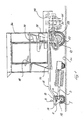
- the embodiment of the present invention shown on the Drawings will be described in connection with employment of the apparatus for displacement or advancement of a number (or cluster) of golf ball harvesters 1, 2, 3 of per se conventional design.
- the harvesters 1, 2 and 3 are coupled to a beam 4 by means of a bolt 5 which extends through lugs 6 and 7 protruding from the beam 4, and a sleeve 8 which is fixedly welded on the forward portion of the harvesters 1, 2 and 3.
- the bolt 5 runs freely through the sleeve 8, whereby the harvesters 1-3 will be pivotal about the bolt 5.
- the harvesters 1 and 3 are pivotally secured to the beam 4 at the ends thereof, while the harvester 2 is secured centrally on the beam 4.
- a drawbar 9 is also disposed centrally on the beam 4 and may be utilised for other types of implements or for towing the apparatus shown on the Drawings.
- the beam 4 is supported from a substrate 10 by means of two spaced-apart wheels 11 and 12.
- the wheels 11 and 12 are advantageously of the castor or swivel type which are secured on mounting brackets or plates 13 and 14 projecting forwardly from the beam 4.
- the beam 4 is interconnected with a frame 15 by means of two bolts 16 and 17 extending in parallel with the frame 4, these bolts extending through lugs which are secured on the beam 4 and the leading ends of the frame 15.
- the frame 15 is provided with a forward cross strut 18 and a substantially centrally disposed carrier plate 19 extending from the cross strut 18 to the rear portion of the frame 15.
- the frame 15 includes a further cross strut 20 for rigidifying and stabilising the frame 15 and for carrying various details and fittings. If desired, the frame 15, the cross struts 18 and 20 and the carrier plate 19 may be wholly or partly covered by a chequered plate (not shown).
- a drive wheel 21 is pivotally or rotatably disposed at the rear portion of the frame 15.
- the drive wheel 21 is journalled in a substantially U-shaped bracket 22 whose bottom shank is provided with a shaft which pivotally extends through the plate 19 and, on the opposing side of the plate 19, carries a wheel 24.
- the shaft 23 is ideally journalled in the plate 19 in some suitable manner.
- the bracket 22 and the drive wheel 21 are thus pivotal in the frame 15 about a shaft, with the aid of the wheel.
- the wheel is included in a steering arrangement which, in the present embodiment, consists of a drive chain or drive belt which, via a guide wheel, extends to a wheel turnable by means of a steering wheel 27.
- the drive wheel 21 will be caused to turn in a direction opposite to the direction in which the steering wheel 27 is turned, whereby the beam 4 and the harvesters 1-3 will be turned in the same direction as the direction of turn of the steering wheel.
- the steering arrangement need not, as in this case, be mechanical but could just as well be hydraulic or operative in any other manner as intimated in Figs. 1 and 2.
- the drive wheel 21 is provided, in its hub, with a per se known hydraulic motor which, via hoses 29 and 30 and a three-way valve 35, is connected to a per se known hydraulic pump via a hydraulic tank 31.
- the hydraulic pump is driven by a suitable type of motor which, in the present embodiment, is illustrated in the form of an internal combustion engine 32.
- a seat 34 is further provided on the frame 15 and possibly also a cab intimated by broken lines on the Drawings. Furthermore, other protective plating and hoods may be provided as intimated by broken lines.
- a pedal 33 is further provided on the frame for switching the valve 35 between its neutral position, forward position and reverse position, and corresponding driving of the hydraulic motor in the drive wheel 21.
- a suitable brake device may be provided if desired, this being optionally hand-operated or foot-operated by a pedal.
- the apparatus and arrangements described in the foregoing are, naturally, not restricted to the displacement or advancement of the illustrated golf ball harvesters 1-3, but may of course be employed, without any major modifications, for advancement or displacement of, for instance, cylinder lawnmowers or the like.
- this may be rendered capable of accepting five such harvesters or even more.
- the frame 15 may be superstructured by a cab 36.
Landscapes
- Life Sciences & Earth Sciences (AREA)
- Engineering & Computer Science (AREA)
- Mechanical Engineering (AREA)
- Soil Sciences (AREA)
- Environmental Sciences (AREA)
- Soil Working Implements (AREA)
- Arrangement And Driving Of Transmission Devices (AREA)
- Vehicle Body Suspensions (AREA)
- Handcart (AREA)
- Arrangement Or Mounting Of Propulsion Units For Vehicles (AREA)
- Surgical Instruments (AREA)
- Electrical Discharge Machining, Electrochemical Machining, And Combined Machining (AREA)
- Confectionery (AREA)
- Vending Machines For Individual Products (AREA)
- Agricultural Machines (AREA)
Priority Applications (1)
| Application Number | Priority Date | Filing Date | Title |
|---|---|---|---|
| AT90850275T ATE102784T1 (de) | 1989-08-17 | 1990-08-08 | Antriebsvorrichtung. |
Applications Claiming Priority (2)
| Application Number | Priority Date | Filing Date | Title |
|---|---|---|---|
| SE8902762 | 1989-08-17 | ||
| SE8902762A SE503102C2 (sv) | 1989-08-17 | 1989-08-17 | Anordning för förflyttning eller framdrivning av ett antal redskap |
Publications (3)
| Publication Number | Publication Date |
|---|---|
| EP0413669A2 true EP0413669A2 (de) | 1991-02-20 |
| EP0413669A3 EP0413669A3 (en) | 1991-08-14 |
| EP0413669B1 EP0413669B1 (de) | 1994-03-16 |
Family
ID=20376686
Family Applications (1)
| Application Number | Title | Priority Date | Filing Date |
|---|---|---|---|
| EP90850275A Expired - Lifetime EP0413669B1 (de) | 1989-08-17 | 1990-08-08 | Antriebsvorrichtung |
Country Status (6)
| Country | Link |
|---|---|
| US (1) | US5105608A (de) |
| EP (1) | EP0413669B1 (de) |
| AT (1) | ATE102784T1 (de) |
| CA (1) | CA2022788C (de) |
| DE (1) | DE69007373T2 (de) |
| SE (1) | SE503102C2 (de) |
Families Citing this family (2)
| Publication number | Priority date | Publication date | Assignee | Title |
|---|---|---|---|---|
| US6109009A (en) | 1998-01-16 | 2000-08-29 | Textron Inc. | Constant speed control for electric greens mower |
| US11147203B2 (en) * | 2014-06-02 | 2021-10-19 | Philip Jensen | Middle mounted implement tractor |
Family Cites Families (15)
| Publication number | Priority date | Publication date | Assignee | Title |
|---|---|---|---|---|
| US1614333A (en) * | 1922-06-17 | 1927-01-11 | Charles C Worthington | Tractor-propelled lawn mower |
| US1771931A (en) * | 1927-07-18 | 1930-07-29 | Joseph N Kinney | Attachment for tractors |
| US2099902A (en) * | 1931-08-05 | 1937-11-23 | Toro Mfg Corp | Tractor propelled gang lawn mower |
| GB586624A (en) * | 1944-12-04 | 1947-03-25 | Simplicity Mfg Company | Tractor for garden cultivators and other implements |
| US2996867A (en) * | 1959-04-13 | 1961-08-22 | Williams Chester | Riding tractor mower |
| GB972920A (en) * | 1962-08-10 | 1964-10-21 | Nat Res Dev | Improvements relating to wheeled vehicles carrying tool bars for cultivation |
| US3823838A (en) * | 1972-09-12 | 1974-07-16 | A Gustafson | Ball retriever |
| US4159749A (en) * | 1977-10-28 | 1979-07-03 | Deere & Company | Harvesting machine frame |
| GB1601252A (en) * | 1978-05-25 | 1981-10-28 | Nickerson Turfmaster Ltd | Vehicles |
| US4478026A (en) * | 1983-06-03 | 1984-10-23 | Ekoeg Industries, Inc. | Gang reel mower |
| CA1203486A (en) * | 1983-10-17 | 1986-04-22 | Arnold E. Mccutcheon | Agricultural work vehicle |
| GB2160091A (en) * | 1984-04-05 | 1985-12-18 | Northern Scient Equipment Limi | Sweeping machine |
| US4688375A (en) * | 1984-06-11 | 1987-08-25 | Mattson Fred P | Mower attachment for farm tractors |
| US4819738A (en) * | 1985-07-29 | 1989-04-11 | Fountain Glen L | Vehicle for supporting an implement |
| FR2604140B1 (fr) * | 1986-09-24 | 1988-12-02 | Bobard Jeune Sa Ets | Tracteur enjambeur a trois roues motrices |
-
1989
- 1989-08-17 SE SE8902762A patent/SE503102C2/sv not_active IP Right Cessation
-
1990
- 1990-08-02 US US07/561,866 patent/US5105608A/en not_active Expired - Lifetime
- 1990-08-07 CA CA002022788A patent/CA2022788C/en not_active Expired - Lifetime
- 1990-08-08 DE DE69007373T patent/DE69007373T2/de not_active Expired - Fee Related
- 1990-08-08 EP EP90850275A patent/EP0413669B1/de not_active Expired - Lifetime
- 1990-08-08 AT AT90850275T patent/ATE102784T1/de not_active IP Right Cessation
Also Published As
| Publication number | Publication date |
|---|---|
| CA2022788C (en) | 2000-12-19 |
| SE503102C2 (sv) | 1996-03-25 |
| SE8902762D0 (sv) | 1989-08-17 |
| SE8902762L (sv) | 1991-02-18 |
| EP0413669B1 (de) | 1994-03-16 |
| DE69007373T2 (de) | 1994-09-01 |
| ATE102784T1 (de) | 1994-04-15 |
| US5105608A (en) | 1992-04-21 |
| CA2022788A1 (en) | 1991-02-18 |
| DE69007373D1 (de) | 1994-04-21 |
| EP0413669A3 (en) | 1991-08-14 |
Similar Documents
| Publication | Publication Date | Title |
|---|---|---|
| US5343960A (en) | Caterpillar track attachment | |
| US7077220B2 (en) | Tractor with rear castor wheels | |
| US4330981A (en) | Towable ganged mower | |
| CA2307926C (en) | Multi-functional self-propelled farm tractor | |
| US6227304B1 (en) | Upper hitch link | |
| US3832835A (en) | Seven gang hydraulic reel mower | |
| US20040055267A1 (en) | Power mower with riding platform for supporting standing-operator | |
| DE602004003581T2 (de) | Gabelstapler mit einem einzelnen vorderrad | |
| US12358549B2 (en) | Drive control system for utility vehicle | |
| US7818903B2 (en) | Vehicle front-end quick connect hitch and lift assembly | |
| US7032694B2 (en) | Propulsion sulky | |
| EP0413669A2 (de) | Antriebsvorrichtung | |
| US8899610B2 (en) | Implement mounting device | |
| FI65527C (fi) | Fordonsburen baerare foer skogsbruksredskap | |
| EP0136910A2 (de) | Landwirtschaftliche Schlepper | |
| GB2177663A (en) | Motor vehicles such as tractors | |
| US4860465A (en) | Snow grooming vehicle and attachments | |
| US4815223A (en) | Snow grooming vehicle and attachments | |
| EP0201526B1 (de) | Schlepper mit gleitlenkung | |
| US20030037984A1 (en) | Front end loader multiple implement attachment apparatus | |
| US20080315556A1 (en) | Tractor hitch attachment connector | |
| WO1993003950A1 (en) | Single-axle work vehicle | |
| EP1310422B1 (de) | Traktor mit Stützelemente und Hebearm besitzendem Anbaurahmen | |
| WO2023223363A1 (en) | Agricultural vehicle | |
| CA1113013A (en) | Multi-purpose vehicle |
Legal Events
| Date | Code | Title | Description |
|---|---|---|---|
| PUAI | Public reference made under article 153(3) epc to a published international application that has entered the european phase |
Free format text: ORIGINAL CODE: 0009012 |
|
| AK | Designated contracting states |
Kind code of ref document: A2 Designated state(s): AT BE CH DE DK ES FR GB GR IT LI LU NL SE |
|
| PUAL | Search report despatched |
Free format text: ORIGINAL CODE: 0009013 |
|
| AK | Designated contracting states |
Kind code of ref document: A3 Designated state(s): AT BE CH DE DK ES FR GB GR IT LI LU NL SE |
|
| 17P | Request for examination filed |
Effective date: 19920204 |
|
| 17Q | First examination report despatched |
Effective date: 19920401 |
|
| GRAA | (expected) grant |
Free format text: ORIGINAL CODE: 0009210 |
|
| AK | Designated contracting states |
Kind code of ref document: B1 Designated state(s): AT BE CH DE DK ES FR GB GR IT LI LU NL SE |
|
| PG25 | Lapsed in a contracting state [announced via postgrant information from national office to epo] |
Ref country code: IT Free format text: LAPSE BECAUSE OF FAILURE TO SUBMIT A TRANSLATION OF THE DESCRIPTION OR TO PAY THE FEE WITHIN THE PRESCRIBED TIME-LIMIT;WARNING: LAPSES OF ITALIAN PATENTS WITH EFFECTIVE DATE BEFORE 2007 MAY HAVE OCCURRED AT ANY TIME BEFORE 2007. THE CORRECT EFFECTIVE DATE MAY BE DIFFERENT FROM THE ONE RECORDED. Effective date: 19940316 Ref country code: LI Effective date: 19940316 Ref country code: ES Free format text: THE PATENT HAS BEEN ANNULLED BY A DECISION OF A NATIONAL AUTHORITY Effective date: 19940316 Ref country code: CH Effective date: 19940316 Ref country code: NL Effective date: 19940316 Ref country code: DK Effective date: 19940316 Ref country code: GR Free format text: LAPSE BECAUSE OF FAILURE TO SUBMIT A TRANSLATION OF THE DESCRIPTION OR TO PAY THE FEE WITHIN THE PRESCRIBED TIME-LIMIT Effective date: 19940316 Ref country code: SE Free format text: THE PATENT HAS BEEN ANNULLED BY A DECISION OF A NATIONAL AUTHORITY Effective date: 19940316 Ref country code: BE Effective date: 19940316 Ref country code: AT Effective date: 19940316 |
|
| REF | Corresponds to: |
Ref document number: 102784 Country of ref document: AT Date of ref document: 19940415 Kind code of ref document: T |
|
| REF | Corresponds to: |
Ref document number: 69007373 Country of ref document: DE Date of ref document: 19940421 |
|
| ET | Fr: translation filed | ||
| REG | Reference to a national code |
Ref country code: CH Ref legal event code: PL |
|
| NLV1 | Nl: lapsed or annulled due to failure to fulfill the requirements of art. 29p and 29m of the patents act | ||
| PG25 | Lapsed in a contracting state [announced via postgrant information from national office to epo] |
Ref country code: LU Free format text: LAPSE BECAUSE OF NON-PAYMENT OF DUE FEES Effective date: 19940831 |
|
| PLBE | No opposition filed within time limit |
Free format text: ORIGINAL CODE: 0009261 |
|
| STAA | Information on the status of an ep patent application or granted ep patent |
Free format text: STATUS: NO OPPOSITION FILED WITHIN TIME LIMIT |
|
| 26N | No opposition filed | ||
| REG | Reference to a national code |
Ref country code: GB Ref legal event code: IF02 |
|
| REG | Reference to a national code |
Ref country code: FR Ref legal event code: ST Effective date: 20070430 |
|
| PG25 | Lapsed in a contracting state [announced via postgrant information from national office to epo] |
Ref country code: FR Free format text: LAPSE BECAUSE OF NON-PAYMENT OF DUE FEES Effective date: 20060831 |
|
| PGFP | Annual fee paid to national office [announced via postgrant information from national office to epo] |
Ref country code: DE Payment date: 20080822 Year of fee payment: 19 |
|
| PGFP | Annual fee paid to national office [announced via postgrant information from national office to epo] |
Ref country code: GB Payment date: 20090827 Year of fee payment: 20 |
|
| PG25 | Lapsed in a contracting state [announced via postgrant information from national office to epo] |
Ref country code: DE Free format text: LAPSE BECAUSE OF NON-PAYMENT OF DUE FEES Effective date: 20100302 |
|
| REG | Reference to a national code |
Ref country code: GB Ref legal event code: PE20 Expiry date: 20100807 |
|
| PG25 | Lapsed in a contracting state [announced via postgrant information from national office to epo] |
Ref country code: GB Free format text: LAPSE BECAUSE OF EXPIRATION OF PROTECTION Effective date: 20100807 |
|
| REG | Reference to a national code |
Ref country code: FR Ref legal event code: D3 Effective date: 20120919 |
|
| PGFP | Annual fee paid to national office [announced via postgrant information from national office to epo] |
Ref country code: FR Payment date: 20120802 Year of fee payment: 20 |
|
| PGRI | Patent reinstated in contracting state [announced from national office to epo] |
Ref country code: FR Effective date: 20120919 |