EP0413901B1 - Backofen mit Heissluftumwälzung - Google Patents
Backofen mit Heissluftumwälzung Download PDFInfo
- Publication number
- EP0413901B1 EP0413901B1 EP90108430A EP90108430A EP0413901B1 EP 0413901 B1 EP0413901 B1 EP 0413901B1 EP 90108430 A EP90108430 A EP 90108430A EP 90108430 A EP90108430 A EP 90108430A EP 0413901 B1 EP0413901 B1 EP 0413901B1
- Authority
- EP
- European Patent Office
- Prior art keywords
- baking oven
- hood
- shaft
- oven according
- baking
- Prior art date
- Legal status (The legal status is an assumption and is not a legal conclusion. Google has not performed a legal analysis and makes no representation as to the accuracy of the status listed.)
- Expired - Lifetime
Links
- 238000010438 heat treatment Methods 0.000 title claims description 3
- 239000002184 metal Substances 0.000 claims 2
- 238000004140 cleaning Methods 0.000 abstract description 9
- 238000000034 method Methods 0.000 description 5
- XLYOFNOQVPJJNP-UHFFFAOYSA-N water Substances O XLYOFNOQVPJJNP-UHFFFAOYSA-N 0.000 description 3
- 235000015173 baked goods and baking mixes Nutrition 0.000 description 2
- 238000010276 construction Methods 0.000 description 2
- 239000007789 gas Substances 0.000 description 2
- 230000005484 gravity Effects 0.000 description 1
- 235000013372 meat Nutrition 0.000 description 1
- 235000013622 meat product Nutrition 0.000 description 1
Images



Classifications
-
- A—HUMAN NECESSITIES
- A21—BAKING; EDIBLE DOUGHS
- A21B—BAKERS' OVENS; MACHINES OR EQUIPMENT FOR BAKING
- A21B1/00—Bakers' ovens
- A21B1/42—Bakers' ovens characterised by the baking surfaces moving during the baking
- A21B1/44—Bakers' ovens characterised by the baking surfaces moving during the baking with surfaces rotating in a horizontal plane
Definitions
- the invention relates to an oven according to the preamble of claim 1.
- Ovens of the type mentioned above are known from DE-OS 14 32 916 or DE-PS 34 31 505.
- the turntable is driven by chain or wire rope, which are arranged below the turntable, and by means of a geared motor arranged outside the furnace.
- the disadvantage here is that there is always a gap between the turntable and the bottom of the oven. Through this gap, dirt or baking residues can fall into the space below. A thorough cleaning of this room is only possible if the turntable is removed. Even after removing the turntable, cleaning is made considerably more difficult by the existing drive elements.
- the invention has for its object to allow a quick and thorough cleaning of the baking chamber floor, possibly also by means of a water jet, in an oven according to the preamble of claim 1, without difficult conditions for driving and accommodating the trolley on the bogie.
- the design of the baking chamber floor and the rotary drive according to the invention enable a quick and thorough cleaning at any time, even by means of a water jet.
- the use of the baking oven while maintaining the advantageous lower rotary drive for the shelf trolley is beyond the bakery operation for other branches of industry where higher demands are placed on hygiene, e.g. in meat processing, possible.
- any gas and steam leakage is avoided by the shaft passage on the oven floor.
- an advantageous solution for a bumpless retraction of the deck trolley is created by forming a straight line of the entry rails with the ramp during the retraction process. Furthermore, the free support of the hood on the shaft provides a slip clutch-like connection, which prevents damage to the drive in the event of an obstruction of the rotary movement of the deck trolley.
- the embodiment according to claim 5 allows centering and guiding of the support profile through the hood during the baking process and when the trolley is moved in and out.
- the embodiment according to claim 6 is particularly expedient, as a result of which only one connecting element, one fastening and one centering and guiding for two different components is achieved.
- the features of claim 7 enable a safe opening and a fixation of the multi-level trolley on the bogie.
- the configuration according to claim 8 provides stiffening and locking of the support profile.
- the oven 1 shown in FIG. 1 is an oven of the known type operated with hot air circulation heating.
- the shelf trolley 2 stands on the bogie 4 in the baking chamber 3 during the baking process and is connected to an externally arranged motor 29 by means of the shaft 5 which penetrates the bottom 6 through the opening 10 and there via a ring gear 27 and chain 28 , slowly rotated.
- the bottom 6 is raised up around the opening 10 so that a cylindrical collar is formed around the shaft 5.
- a bushing 31, which serves as a sliding bearing for the shaft 5, can also be arranged in the collar 8.
- a U-shaped plate 14 with the legs 15 and 16 pointing upward is asymmetrical welded on.
- the support profile 18, which is designed as a bogie 4 and is provided with a bore 19 and rails 17, is arranged so as to rest freely.
- the rails 17 are equipped in the drive-up area with support rollers 22 and at the end with stops 23.
- the hood 7 is fastened to the end of the shaft 5 by means of a screw 20.
- the screw head is designed so that it serves as a centering for the support profile 18 and as a holder in the tilted position.
- the support profile 18 is equipped with a bore 191 designed according to the screw head 21.
- the support profile 18 is U-shaped with legs 24 pointing downward.
- the oven 1 is equipped at the bottom with support points 13, which reduce the heat output to the floor and create space for the drive elements for the shaft 5.
- a heat-resistant seal 12 is arranged between the collar 8 and the hood 7.
- the device works as follows: When retracting the trolley 2 loaded with baked goods over the ramp 26 provided in the door area, the wheels 25 roll against the rails 17 and press the support profile 18 (rocker) downward (FIG. 2), so that the rails 17 with the ramp 26 are straight Form a line, which ensures smooth entry and exit.
- the support profile 18 is supported on the leg 15.
- the support rollers 22 ensure that the seesaw is not raised when the front wheels 25 of the deck trolley 2 roll over the support point of the leg 15. Before the center of gravity of the deck trolley 2 rolls over the support point, the rear wheels are also retracted into the rails 17.
- the support profile 18 (rocker) is now pressed onto the leg 16 by the carriage weight.
- the stops 23 limit the entry area of the now vertical shelf trolley 2.
- the shelf trolley 2 is thus inserted in the baking space 3 on the bogie 4 ready for rotation.
- the heat-resistant seal 12 prevents steam and other gases from escaping in the drive area of the shaft 5 lying outside the baking chamber 3 during the baking and turning process.
- the rocker is centered and non-slip in the tilted position through the bore 19 through which the hood 7 projects held. Since the hood 7 rests only loosely on the upper end of the shaft 5, a type of slip clutch is provided which protects the drive elements in the event of an obstacle. 4, where the hood is fastened by means of the screw 20, the screw head 21 ensures the mounting and centering of the rocker (support profile 18).
- the legs 24 contribute to the stiffening of the support profile 18 and at the same time serve as stops for preventing a rotational movement of the support profile, for example when the stacked trolley 2 moves onto the rocker. Since the floor 6 is raised all around the opening 10, a quick and thorough cleaning, also by means of a water jet, is given at all times. In the case of a segmented construction of the furnace, care must be taken that the lateral collar 30 on the furnace walls 9 over the expected flood limit is measured. The cylindrical collar 8 is covered by the hood 7 splash-proof. During cleaning, the bogie 4 can also be lifted off if necessary. This is easily possible due to the free support of the support profile 18.
- the bottom of the oven can be cleaned quickly at any time while maintaining the advantageous lower rotary drive, so that the oven can be used not only in the bakery, but also in meat products factories or similar establishments in which significantly higher ones hygienic cleaning requirements are made.
Landscapes
- Life Sciences & Earth Sciences (AREA)
- Engineering & Computer Science (AREA)
- Food Science & Technology (AREA)
- Baking, Grill, Roasting (AREA)
- Drying Of Solid Materials (AREA)
- Electric Ovens (AREA)
- Commercial Cooking Devices (AREA)
- Coating Apparatus (AREA)
Description
- Die Erfindung betrifft einen Backofen nach dem Oberbegriff des Patentanspruches 1.
- Backöfen der oben genannten Gattung sind aus der DE-OS 14 32 916 oder DE-PS 34 31 505 bekannt. Bei diesen Backöfen wird der mit Backgut beladene Etagenwagen auf eine antreibbare Drehscheibe gestellt und während des Backvorganges langsam gedreht. Die Drehscheibe wird über Kette oder Drahtseil, welche unterhalb der Drehscheibe angeordnet sind und mittels eines außerhalb des Ofens angeordneten Getriebemotors angetrieben. Nachteilig hierbei ist, daß zwischen der Drehscheibe und dem Boden des Backofens immer ein Spalt vorhanden ist. Durch diesen Spalt können Schmutz oder Backrückstände in den darunter liegenden Raum fallen.
Eine gründliche Reinigung dieses Raumes ist nur möglich, wenn die Drehscheibe entfernt wird. Selbst nach der Entfernung der Drehscheibe wird die Reinigung durch die vorhandenen Antriebselemente erheblich erschwert. Es sind auch Backöfen bekannt (z.B. DE-PS 18 00 800), bei denen der Drehantrieb von oben erfolgt. Zwar sind bei dieser Bauart gute Reinigungsmöglichkeiten für den Boden des Backofens gegeben, aber der Drehantrieb von oben erfordert eine größere Bauhöhe des Backofens und es sind Stützkonstruktionen für die Lastaufnahme erforderlich. - Der Erfindung liegt die Aufgabe zugrunde, bei einem Backofen gemäß dem Oberbegriff des Patentanspruches 1 eine schnelle und gründliche Reinigung des Backraumbodens, gegebenenfalls auch mittels Wasserstrahls, zu ermöglichen, ohne daß erschwerte Bedingungen für den Antrieb und die Aufnahme des Etagenwagens auf dem Drehgestell eintreten.
- Die Aufgabe wird erfindungsgemäß durch die im Kennzeichen des Patentanspruches 1 angegebenen Merkmale gelöst. Weitere vorteilhafte Ausgestaltungen der Erfindung ergeben sich aus den Unteransprüchen.
- Die erfindungsgemäße Gestaltung des Backraumbodens und des Drehantriebes ermöglichen jederzeit eine schnelle und gründliche Reinigung auch mittels Wasserstrahles. Dadurch ist der Einsatz des Backofens bei Beibehaltung des vorteilhaften unteren Drehantriebes für den Etagenwagen über den Bäckereibetrieb hinaus für andere Industriezweige, wo höhere Anforderungen an die Hygiene gestellt werden, wie z.B. bei der Fleischverarbeitung, möglich.
- Entsprechend der Ausgestaltung nach Anspruch 2 ist eine sichere seitliche Führung für die Welle des Drehantriebes gegeben.
- Gemäß der Ausgestaltung nach Anspruch 3 wird auch jeglicher Gas- und Dampfaustritt durch die Wellendurchführung am Backofenboden vermieden.
- In Weiterbildung des Erfindungsgedankens ist nach Anspruch 4 eine vorteilhafte Lösung für ein stoßfreies Einfahren des Etagenwagens durch Bildung einer geraden Linie der Einfahrschienen mit der Auffahrschräge während des Einfahrvorganges geschaffen. Ferner ist durch die freie Auflage der Haube auf der Welle eine rutschkupplungartige Verbindung gegeben, die im Falle einer Behinderung der Drehbewegung des Etagenwagens eine Beschädigung des Antriebes vermeidet.
- Die Ausgestaltung nach Anspruch 5 erlaubt eine Zentrierung und Führung des Tragprofiles durch die Haube während des Backprozesses und beim Ein- und Ausfahren des Etagenwagens.
- Besonders zweckmäßig ist die Ausgestaltung nach Anspruch 6, wodurch über nur ein Verbindungselement, einmal eine Befestigung und andererseits eine Zentrierung und Führung für zwei unterschiedliche Bauteile erreicht ist.
- Ein sicheres Auffahren und eine Fixierung des Etagenwagens auf dem Drehgestell ermöglichen die Merkmale des Anspruches 7.
- Durch die Ausgestaltung nach Anspruch 8 ist eine Versteifung und Arretierung des Tragprofiles gegeben.
- Ausführungsbeispiele sind an Hand der Zeichnung beschrieben.
Es zeigt: - Fig. 1 einen senkrechten Schnitt durch einen schematisch dargestellten Backofen
- Fig. 2 den Backraumboden mit Drehgestell in der Einfahrphase des Etagenwagens
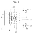
- Fig. 3 eine Sicht auf das Drehgestell ohne Etagenwagen von oben
- Fig. 4 einen Schnitt gemäß der Linie I-I entsprechend Fig. 3 in vergrößertem Maßstab, wobei die Haube mit einer Schraube befestigt ist.
- Bei dem in Fig. 1 dargestellten Backofen 1 handelt es sich um einen mit Heißluft-Umwälzheizung betriebenen Ofen in bekannter Bauart. Der Etagenwagen 2 steht während des Backvorganges auf dem Drehgestell 4 im Backraum 3 und wird über die Welle 5, die den Boden 6 durch die Öffnung 10 nach unten durchgreift und dort über einen Zahnkranz 27 und Kette 28 mit einem außen angeordneten Motor 29 in Verbindung steht, langsam gedreht.
- Um die Öffnung 10 ist der Boden 6 hochgekragt, so daß ein zylindrischer Kragen um die Welle 5 gebildet ist. Im Kragen 8 kann noch eine Büchse 31, die als Gleitlager für die Welle 5 dient, angeordnet sein. Auf dem oberen Ende der Welle 5 ist eine das Drehgestell 4 tragende und den Kragen 8 umschließende Haube 7 angeordnet.
- An der Haube 7 ist ein mit den Schenkeln 15 und 16 nach oben weisendes u-förmiges Blech 14 asymmetrisch angeschweißt. Auf den Schenkeln 15 und 16 ist das als Drehgestell 4 ausgebildete mit einer Bohrung 19 und Schienen 17 versehene Tragprofil 18 frei aufliegend angeordnet. Die Schienen 17 sind im Auffahrbereich mit Stützrollen 22 und am Ende mit Anschlägen 23 ausgerüstet.
- Gemäß der Ausbildung nach Fig. 4 ist die Haube 7 mittels einer Schraube 20 auf dem Ende der Welle 5 befestigt. Der Schraubkopf ist dabei so ausgebildet, daß er für das Tragprofil 18 als Zentrierung und bei der Kippstellung als Halterung dient. Zu diesem Fall ist das Tragprofil 18 mit einer nach Maßgabe des Schraubenkopfes 21 gestalteten Bohrung 191 ausgerüstet. Das Tragprofil 18 ist u-förmig mit nach unten weisenden Schenkeln 24 ausgebildet.
Der Backofen 1 ist unten mit Stützpunkten 13 ausgerüstet, die eine Reduzierung der Wärmeabgabe an den Fußboden bewirken und Platz für die Antriebselemente für die Welle 5 schaffen. Zwischen Kragen 8 und Haube 7 ist eine wärmebeständige Dichtung 12 angeordnet.
Die Wirkung der Vorrichtung ist wie folgt:
Beim Einfahren des mit Backgut beladenen Etagenwagen 2 über die im Türbereich vorgesehene Auffahrschräge 26 rollen die Räder 25 gegen die Schienen 17 und drücken das Tragprofil 18 (Wippe) nach unten (Fig. 2), so daß die Schienen 17 mit der Auffahrschräge 26 eine gerade Linie bilden, wodurch ein stoßfreies Ein- und Ausfahren gegeben ist.
Das Tragprofil 18 stützt sich dabei auf den Schenkel 15 ab. Die Stützrollen 22 sorgen dafür, daß die Wippe sich nicht hochstellt, wenn die vorderen Räder 25 des Etagenwagens 2 über den Abstützpunkt des Schenkels 15 rollen. Bevor der Schwerpunkt des Etagenwagens 2 über den Abstützpunkt rollt, sind auch die hinteren Räder in den Schienen 17 eingefahren. Das Tragprofil 18 (Wippe) wird nun vom Wagengewicht auf den Schenkel 16 gedrückt. Die Anschläge 23 begrenzen den Einfahrbereich des nun senkrecht stehenden Etagenwagen 2. Damit ist der Etagenwagen 2 drehbereit im Backraum 3 auf dem Drehgestell 4 eingebracht. Die warmfeste Dichtung 12 verhindert bei Back- und Drehvorgang ein Austreten von Dampf und anderen Gasen in dem außerhalb des Backraumes 3 liegenden Antriebsbereich der Welle 5. Durch die Bohrung 19, durch welche die Haube 7 ragt, ist die Wippe zentriert und verrutschfest in der Kippstellung gehalten. Da die Haube 7 nur lose auf dem oberen Ende der Welle 5 aufliegt, ist eine Art Rutschkupplung gegeben, die im Falle eines Hindernisses die Antriebselemente schonen. Bei der Ausführung nach Fig. 4, wo die Haube mittels der Schraube 20 befestigt ist, wird durch den Schraubenkopf 21 die Halterung und Zentrierung der Wippe (Tragprofil 18) gewährleistet. Die Schenkel 24 tragen zur Versteifung des Tragprofiles 18 bei und dienen gleichzeitig als Anschläge für die Verhinderung einer Drehbewegung des Tragprofiles, z.B. beim Auffahrvorgang des Etagenwagens 2 auf die Wippe. Da der Boden 6 ringsrum um die Öffnung 10 hochgekragt ist, ist jederzeit eine schnelle und gründliche Reinigung, auch mittels Wasserstrahl, gegeben. Bei einer Segmentbauweise des Ofens ist darauf zu achten, daß der seitliche Kragen 30 an den Ofenwänden 9 über die zu erwartende Überflutungsgrenze bemessen ist. Der zylindrische Kragen 8 ist durch die Haube 7 spritzwasserdicht abgedeckt.
Während der Reinigung kann das Drehgestell 4 falls erforderlich auch abgehoben werden. Dies ist durch die freie Auflage des Tragprofiles 18 problemlos möglich. Durch den Wegfall des Spaltes zwischen Drehscheibe und Boden des Backofens kann bei Beibehaltung des vorteilhaften unteren Drehantriebes jederzeit eine schnelle Reinigung des Backraumbodens vorgenommen werden, so daß der Backofen nicht nur im Bäckereibetrieb, sondern auch in Fleischwarenfabriken oder ähnlichen Betrieben einsetzbar ist, in denen bedeutend höhere hygienische Anforderungen an die Reinigung gestellt werden.
Claims (8)
- Backofen mit Heißluft-Umwälzheizung, in dessen Backraum ein das Backgut aufnehmender und während des Backens um eine senkrechte Achse rotierender Etagenwagen auf einem am Boden des Backraumes befindlichen Drehgestell steht, wobei das Drehgestell eine unterhalb des Backraumes gelagerte Welle aufweist, an welcher der Drehantrieb angreift und welche durch eine Öffnung im Boden in den Backraum ragt, dadurch gekennzeichnet, daß der Boden (6) des Backraumes (3) um die Öffnung (10) für die Welle (5) hochgekragt ist, wobei der so gebildete zylindrische Kragen (8) durch eine das Drehgestell (4) tragende am oberen Ende der Welle (5) angeordneten Haube (7) umschlossen ist.
- Backofen nach Anspruch 1, dadurch gekennzeichnet, daß der Kragen (8) mit einer Büchse (31) versehen ist und als Gleitlager für die Welle (5) ausgebildet ist.
- Backofen nach Anspruch 1 und 2, dadurch gekennzeichnet, daß zwischen Kragen (8) und Haube (7) eine temperaturbeständige Dichtung (12) angeordnet ist.
- Backofen nach Anspruch 1-3, dadurch gekennzeichnet, daß an der Haube (7) ein u-förmiges Blech (14) asymmetrisch mit den Schenkeln (15, 16) nach oben befestigt ist, auf denen frei aufliegend ein mit Schienen (17) ausgerüstetes wippbares Tragprofil (18) angeordnet ist.
- Backofen nach Anspruch 4, dadurch gekennzeichnet, daß das Tragprofil (18) mit einer Bohrung (19), die größer als der Außendurchmesser der Haube (7) ist, versehen ist.
- Backofen nach Anspruch 1-4, dadurch gekennzeichnet, daß die Haube (7) mittels einer Schraube (20) auf der Welle (5) befestigt ist, wobei der Schraubenkopf (21) so gestaltet ist, daß dieser mit einer nach Maßgabe des Schraubenkopfes (21) eingebrachten Bohrung (191) des Tragprofiles (18) in Wirkungsverbindung steht.
- Backofen nach Anspruch 4, dadurch gekennzeichnet, daß an den Schienen (17) im Auffahrbereich Stützrollen (22) und am Ende Anschläge (23) angeordnet sind.
- Backofen nach Anspruch 4, dadurch gekennzeichnet, daß das Tragprofil (18) aus einem u-förmigen Blech mit nach unten weisenden Schenkeln (24) besteht.
Priority Applications (1)
| Application Number | Priority Date | Filing Date | Title |
|---|---|---|---|
| AT90108430T ATE82669T1 (de) | 1989-08-25 | 1990-05-04 | Backofen mit heissluftumwaelzung. |
Applications Claiming Priority (2)
| Application Number | Priority Date | Filing Date | Title |
|---|---|---|---|
| DE3928172 | 1989-08-25 | ||
| DE3928172A DE3928172C1 (de) | 1989-08-25 | 1989-08-25 |
Publications (2)
| Publication Number | Publication Date |
|---|---|
| EP0413901A1 EP0413901A1 (de) | 1991-02-27 |
| EP0413901B1 true EP0413901B1 (de) | 1992-11-25 |
Family
ID=6387897
Family Applications (1)
| Application Number | Title | Priority Date | Filing Date |
|---|---|---|---|
| EP90108430A Expired - Lifetime EP0413901B1 (de) | 1989-08-25 | 1990-05-04 | Backofen mit Heissluftumwälzung |
Country Status (5)
| Country | Link |
|---|---|
| EP (1) | EP0413901B1 (de) |
| AT (1) | ATE82669T1 (de) |
| DE (2) | DE3928172C1 (de) |
| DK (1) | DK0413901T3 (de) |
| ES (1) | ES2037501T3 (de) |
Families Citing this family (3)
| Publication number | Priority date | Publication date | Assignee | Title |
|---|---|---|---|---|
| RU2188548C1 (ru) * | 2001-05-16 | 2002-09-10 | Закрытое Акционерное Общество Научно-Производственное Предприятие Фирма "Восход" | Хлебопекарная печь |
| CN114831145B (zh) * | 2022-04-19 | 2023-04-28 | 广州生长地农业科技有限公司 | 一种月饼生产用智能加工设备及月饼生产方法 |
| IT202200021897A1 (it) * | 2022-10-24 | 2024-04-24 | Mondial Forni S P A | Piattaforma per un carrello e forno rotativo comprendente tale piattaforma |
Family Cites Families (6)
| Publication number | Priority date | Publication date | Assignee | Title |
|---|---|---|---|---|
| DE1432916A1 (de) * | 1964-08-11 | 1969-04-17 | Tore Andersson | Vorrichtung an Backoefen |
| US3412695A (en) * | 1965-09-20 | 1968-11-26 | Tore S. Andersson | Baking ovens |
| US3595178A (en) * | 1967-10-06 | 1971-07-27 | Dahlen Elektro Ab | Bakery oven |
| DE2547209A1 (de) * | 1975-10-22 | 1977-04-28 | Haas & Sohn Ernst W | Geraet zur waermebehandlung von lebensmitteln und speisen |
| FR2467548A1 (fr) * | 1979-10-25 | 1981-04-30 | Fringand Ets | Procede de fabrication d'un four et four de boulangerie obtenu par ce procede |
| DE3431505C1 (de) * | 1984-08-28 | 1985-11-28 | Werner & Pfleiderer, 7000 Stuttgart | Backofen mit Heissluftumwaelzheizung |
-
1989
- 1989-08-25 DE DE3928172A patent/DE3928172C1/de not_active Expired - Fee Related
-
1990
- 1990-05-04 EP EP90108430A patent/EP0413901B1/de not_active Expired - Lifetime
- 1990-05-04 DE DE9090108430T patent/DE59000504D1/de not_active Expired - Fee Related
- 1990-05-04 AT AT90108430T patent/ATE82669T1/de not_active IP Right Cessation
- 1990-05-04 ES ES199090108430T patent/ES2037501T3/es not_active Expired - Lifetime
- 1990-05-04 DK DK90108430.1T patent/DK0413901T3/da active
Also Published As
| Publication number | Publication date |
|---|---|
| DE59000504D1 (de) | 1993-01-07 |
| ES2037501T3 (es) | 1993-06-16 |
| DK0413901T3 (da) | 1993-03-29 |
| EP0413901A1 (de) | 1991-02-27 |
| ATE82669T1 (de) | 1992-12-15 |
| DE3928172C1 (de) | 1990-09-20 |
Similar Documents
| Publication | Publication Date | Title |
|---|---|---|
| DE2519849C2 (de) | Kammerofen für Nahrungsmittel | |
| DE1800800C3 (de) | Backofen | |
| EP0434862B1 (de) | Aushebevorrichtung, insbesondere für Förderbahnen | |
| DE2444172C2 (de) | Anlage zur Oberflächenbehandlung von Werkstücken | |
| DE2038133C3 (de) | Vorrichtung zur Bildung von Drahtbunden aus aufeinanderfolgend zugeführten Ringschlingen eines Drahtstranges | |
| EP0413901B1 (de) | Backofen mit Heissluftumwälzung | |
| DE2613149B2 (de) | Vorrichtung zum Reinigen von Förderbändern | |
| CH453203A (de) | Beschickungsvorrichtung | |
| DE4209689C2 (de) | Elektromotorisch betriebene Vorrichtung zum Heben und Kippen des fahrbaren Bottichs einer Teigknetmaschine | |
| DE2261658C3 (de) | Regalförderzeug | |
| DE10258728B3 (de) | Ofen zur Wärmebehandlung von Teilen | |
| DE2347916A1 (de) | Antriebsvorrichtung zum gleichzeitigen anheben von tueren an einem aufzug | |
| DE10013595B4 (de) | Elektromotorisch betriebene Vorrichtung zum Heben und Kippen eines fahrbaren Bottichs einer Teigknetmaschine | |
| DE2327598A1 (de) | Vakuum-entgasungsvorrichtung | |
| DE971874C (de) | Austragsvorrichtung fuer Durchlauf-Gluehoefen u. dgl. | |
| EP0224768B1 (de) | Abschreckbad mit angebauter Schleuse | |
| EP1746065B1 (de) | Oberflächenbehandlungsanlage mit einer Hubstation, und Hubstation mit nichtzylindrischen Führungsrollen | |
| DE931956C (de) | Austragsvorrichtung an Industrieoefen | |
| DE2639542C2 (de) | Vorrichtung für Galvanik-Wagen | |
| DE85559C (de) | ||
| DE2629633B2 (de) | Um eine vertikale Drehachse antreibbare Schleuderscheibe einer Vorrichtung zum Sortieren von Münzen o.dgl | |
| DE2758282C2 (de) | ||
| DE957533C (de) | Einrichtung fuer Obstsortiermaschine, durch welche das in Harassen ankommende Obst in die Maschine befoerdert wird | |
| DE3234694C2 (de) | Elektrischer Brotröster mit stangenförmiger Heizvorrichtung | |
| EP4272557A1 (de) | Transportvorrichtung mit hub- und fördervorrichtung zum transport von nahrungsmittelteig |
Legal Events
| Date | Code | Title | Description |
|---|---|---|---|
| PUAI | Public reference made under article 153(3) epc to a published international application that has entered the european phase |
Free format text: ORIGINAL CODE: 0009012 |
|
| 17P | Request for examination filed |
Effective date: 19901122 |
|
| AK | Designated contracting states |
Kind code of ref document: A1 Designated state(s): AT DE DK ES FR IT SE |
|
| 17Q | First examination report despatched |
Effective date: 19920506 |
|
| GRAA | (expected) grant |
Free format text: ORIGINAL CODE: 0009210 |
|
| AK | Designated contracting states |
Kind code of ref document: B1 Designated state(s): AT DE DK ES FR IT SE |
|
| REF | Corresponds to: |
Ref document number: 82669 Country of ref document: AT Date of ref document: 19921215 Kind code of ref document: T |
|
| ET | Fr: translation filed | ||
| REF | Corresponds to: |
Ref document number: 59000504 Country of ref document: DE Date of ref document: 19930107 |
|
| ITF | It: translation for a ep patent filed | ||
| REG | Reference to a national code |
Ref country code: DK Ref legal event code: T3 |
|
| REG | Reference to a national code |
Ref country code: ES Ref legal event code: FG2A Ref document number: 2037501 Country of ref document: ES Kind code of ref document: T3 |
|
| PLBE | No opposition filed within time limit |
Free format text: ORIGINAL CODE: 0009261 |
|
| STAA | Information on the status of an ep patent application or granted ep patent |
Free format text: STATUS: NO OPPOSITION FILED WITHIN TIME LIMIT |
|
| 26N | No opposition filed | ||
| PGFP | Annual fee paid to national office [announced via postgrant information from national office to epo] |
Ref country code: SE Payment date: 19940412 Year of fee payment: 5 |
|
| PGFP | Annual fee paid to national office [announced via postgrant information from national office to epo] |
Ref country code: ES Payment date: 19940419 Year of fee payment: 5 |
|
| PGFP | Annual fee paid to national office [announced via postgrant information from national office to epo] |
Ref country code: FR Payment date: 19940428 Year of fee payment: 5 |
|
| PGFP | Annual fee paid to national office [announced via postgrant information from national office to epo] |
Ref country code: DK Payment date: 19940630 Year of fee payment: 5 |
|
| EAL | Se: european patent in force in sweden |
Ref document number: 90108430.1 |
|
| PG25 | Lapsed in a contracting state [announced via postgrant information from national office to epo] |
Ref country code: DK Effective date: 19950504 |
|
| REG | Reference to a national code |
Ref country code: DK Ref legal event code: EBP |
|
| PG25 | Lapsed in a contracting state [announced via postgrant information from national office to epo] |
Ref country code: SE Effective date: 19950505 Ref country code: ES Free format text: LAPSE BECAUSE OF NON-PAYMENT OF DUE FEES Effective date: 19950505 |
|
| EUG | Se: european patent has lapsed |
Ref document number: 90108430.1 |
|
| PG25 | Lapsed in a contracting state [announced via postgrant information from national office to epo] |
Ref country code: FR Effective date: 19960229 |
|
| REG | Reference to a national code |
Ref country code: FR Ref legal event code: ST |
|
| REG | Reference to a national code |
Ref country code: FR Ref legal event code: ST |
|
| PGFP | Annual fee paid to national office [announced via postgrant information from national office to epo] |
Ref country code: AT Payment date: 19980409 Year of fee payment: 9 |
|
| PGFP | Annual fee paid to national office [announced via postgrant information from national office to epo] |
Ref country code: DE Payment date: 19980724 Year of fee payment: 9 |
|
| REG | Reference to a national code |
Ref country code: ES Ref legal event code: FD2A Effective date: 19990201 |
|
| PG25 | Lapsed in a contracting state [announced via postgrant information from national office to epo] |
Ref country code: AT Free format text: LAPSE BECAUSE OF NON-PAYMENT OF DUE FEES Effective date: 19990504 |
|
| PG25 | Lapsed in a contracting state [announced via postgrant information from national office to epo] |
Ref country code: DE Free format text: LAPSE BECAUSE OF NON-PAYMENT OF DUE FEES Effective date: 20000301 |
|
| PG25 | Lapsed in a contracting state [announced via postgrant information from national office to epo] |
Ref country code: IT Free format text: LAPSE BECAUSE OF NON-PAYMENT OF DUE FEES;WARNING: LAPSES OF ITALIAN PATENTS WITH EFFECTIVE DATE BEFORE 2007 MAY HAVE OCCURRED AT ANY TIME BEFORE 2007. THE CORRECT EFFECTIVE DATE MAY BE DIFFERENT FROM THE ONE RECORDED. Effective date: 20050504 |