EP0414075A1 - Dispositif de remplissage de récipients - Google Patents
Dispositif de remplissage de récipients Download PDFInfo
- Publication number
- EP0414075A1 EP0414075A1 EP90115441A EP90115441A EP0414075A1 EP 0414075 A1 EP0414075 A1 EP 0414075A1 EP 90115441 A EP90115441 A EP 90115441A EP 90115441 A EP90115441 A EP 90115441A EP 0414075 A1 EP0414075 A1 EP 0414075A1
- Authority
- EP
- European Patent Office
- Prior art keywords
- storage container
- metering chamber
- container
- liquid
- return gas
- Prior art date
- Legal status (The legal status is an assumption and is not a legal conclusion. Google has not performed a legal analysis and makes no representation as to the accuracy of the status listed.)
- Granted
Links
- 239000007788 liquid Substances 0.000 claims abstract description 106
- 238000007789 sealing Methods 0.000 claims abstract description 26
- 238000003032 molecular docking Methods 0.000 claims description 7
- 238000006073 displacement reaction Methods 0.000 abstract description 7
- 230000008878 coupling Effects 0.000 abstract 1
- 238000010168 coupling process Methods 0.000 abstract 1
- 238000005859 coupling reaction Methods 0.000 abstract 1
- 238000005429 filling process Methods 0.000 description 14
- CURLTUGMZLYLDI-UHFFFAOYSA-N Carbon dioxide Chemical compound O=C=O CURLTUGMZLYLDI-UHFFFAOYSA-N 0.000 description 4
- 238000005187 foaming Methods 0.000 description 4
- 238000000034 method Methods 0.000 description 3
- 230000002093 peripheral effect Effects 0.000 description 3
- 230000015572 biosynthetic process Effects 0.000 description 2
- 229910002092 carbon dioxide Inorganic materials 0.000 description 2
- 235000014171 carbonated beverage Nutrition 0.000 description 2
- 238000010276 construction Methods 0.000 description 2
- 230000000694 effects Effects 0.000 description 2
- 230000036316 preload Effects 0.000 description 2
- 230000005587 bubbling Effects 0.000 description 1
- 239000001569 carbon dioxide Substances 0.000 description 1
- 230000003247 decreasing effect Effects 0.000 description 1
- 230000001419 dependent effect Effects 0.000 description 1
- 230000008030 elimination Effects 0.000 description 1
- 238000003379 elimination reaction Methods 0.000 description 1
- 230000005484 gravity Effects 0.000 description 1
- 238000007654 immersion Methods 0.000 description 1
- 230000010354 integration Effects 0.000 description 1
Images


Classifications
-
- B—PERFORMING OPERATIONS; TRANSPORTING
- B67—OPENING, CLOSING OR CLEANING BOTTLES, JARS OR SIMILAR CONTAINERS; LIQUID HANDLING
- B67C—CLEANING, FILLING WITH LIQUIDS OR SEMILIQUIDS, OR EMPTYING, OF BOTTLES, JARS, CANS, CASKS, BARRELS, OR SIMILAR CONTAINERS, NOT OTHERWISE PROVIDED FOR; FUNNELS
- B67C3/00—Bottling liquids or semiliquids; Filling jars or cans with liquids or semiliquids using bottling or like apparatus; Filling casks or barrels with liquids or semiliquids
- B67C3/02—Bottling liquids or semiliquids; Filling jars or cans with liquids or semiliquids using bottling or like apparatus
- B67C3/20—Bottling liquids or semiliquids; Filling jars or cans with liquids or semiliquids using bottling or like apparatus with provision for metering the liquids to be introduced, e.g. when adding syrups
- B67C3/204—Bottling liquids or semiliquids; Filling jars or cans with liquids or semiliquids using bottling or like apparatus with provision for metering the liquids to be introduced, e.g. when adding syrups using dosing chambers
-
- B—PERFORMING OPERATIONS; TRANSPORTING
- B67—OPENING, CLOSING OR CLEANING BOTTLES, JARS OR SIMILAR CONTAINERS; LIQUID HANDLING
- B67C—CLEANING, FILLING WITH LIQUIDS OR SEMILIQUIDS, OR EMPTYING, OF BOTTLES, JARS, CANS, CASKS, BARRELS, OR SIMILAR CONTAINERS, NOT OTHERWISE PROVIDED FOR; FUNNELS
- B67C3/00—Bottling liquids or semiliquids; Filling jars or cans with liquids or semiliquids using bottling or like apparatus; Filling casks or barrels with liquids or semiliquids
- B67C3/02—Bottling liquids or semiliquids; Filling jars or cans with liquids or semiliquids using bottling or like apparatus
- B67C3/22—Details
- B67C3/26—Filling-heads; Means for engaging filling-heads with bottle necks
- B67C2003/2657—Filling-heads; Means for engaging filling-heads with bottle necks specially adapted for filling cans
Definitions
- the invention relates to a device for filling containers, in particular bottles or cans, with a predetermined amount of a liquid.
- a liquid contained in a storage kettle is usually filled into containers, such as cans or bottles, by successively docking the containers to a filling head which is arranged on the storage container and has an outlet closing valve which opens for filling the liquid into the containers becomes.
- the liquid flows from the storage container under the effect of gravity through the open valve into the container to be filled.
- a filling head must be provided, which first pressurizes the container with the pressure which also acts on the liquid in the storage container, so that the container to be filled is pre-stressed before the filling of the liquid is started.
- the biasing gas is displaced from the container.
- the fill level in the container is determined by the position of the end of the vent line in the upper part of the container to be filled. Since the inner volume of the container is usually not constant, precise volume metering of the filling quantity is not possible in this way.
- the invention has for its object to provide a device of the type described above for filling volumetrically measured amounts of a liquid.
- a storage container holding the liquid to be filled and a metering chamber of predetermined volume connected to the storage container via a closable liquid passage, which has a closable liquid outlet and centering and sealing means for docking successive containers to be filled.
- the invention offers the advantage that it allows the filling of precisely specified quantities of a liquid into containers such as cans or bottles to be docked one after the other.
- the filling quantities in successive containers are no longer dependent on the internal volume of the respective container.
- the features of the claims relating to the arrangement of the metering chamber within the storage container are of particular and independent inventive importance. This integration of the dosing chamber into the storage container not only achieves a compact and space-saving construction of the filling device, but also results in a conception of the filling device that is particularly suitable for filling a liquid in the storage container under increased pressure.
- the externally adjustable displacement body which is inserted into the metering chamber in accordance with claims 8 and 9 makes the filling device according to the invention particularly flexible because it can be adjusted to different volumetric quantities which can be determined.
- the features of the claims which relate to the arrangement of the displacement body in the metering chamber, also have independent inventive significance.
- the displacer also serves as an assembly and guide body for several components of the filling device proposed according to the invention and thereby makes the filling head of the device a compact, separately mountable and easy-to-use and adjustable structural unit which can be mounted outside the storage container and inserted as a whole into the storage container.
- the filling device according to the invention is structurally simple and safe in its function because it has only a few moving parts.
- the embodiment according to claim 7 is considered to be particularly advantageous because the inner metering chamber part simultaneously has a valve function for the passage of the liquid to the metering chamber.
- the design of the return gas pipe as the carrier and actuating member of the outlet valve of the metering chamber toward the respective docked container increases the simplicity of the construction of the filling device according to the invention, since additional parts that can be moved relative to each other are saved.
- the filling process can advantageously be accelerated by reducing the internal pressure of the container during filling according to the invention.
- the decreasing filling speed towards the end of the filling process causes the liquid flow to calm down, which reduces the risk of the liquid foaming in the container to be filled.
- the filling head versions in which the dosing chamber is filled from below, ensure that the dosing chamber is filled smoothly and yet quickly without the formation of bubbles and vortices that significantly impair the dosing process.
- the invention provides in a very advantageous manner a filling device for metered filling of liquids with a structurally compact, easy to assemble, handle and adjust and at the same time extremely functionally reliable and fast filling head, which in a particularly advantageous manner also fills under pressure standing liquid allowed.
- the invention advantageously provides an extremely fast filling valve which, with high functional reliability, allows high filling speeds of precisely metered filling quantities.
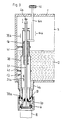
- the filling device shown in FIG. 1 has a storage container 1, which can be designed in a known manner as a ring bowl rotating around a vertical axis (see FIG. 5).
- a liquid 2 to be filled is contained in the ring bowl.
- the liquid level is kept constant by known means, not shown in the drawing.
- Above the liquid level there is a gas space 3 which contains a gas under an increased pressure.
- a pot-shaped container extension 4 is attached to the underside of the storage container 1, the outside of which is designed as a guide for a centering and sealing bell 6.
- the centering and sealing bell 6 has at its lower outlet a seal 7, with which it is pressed onto a container 8 to be filled, for example a can or bottle. Successive containers 8 are held by means of a carrier 9 during the filling process.
- the centering and sealing bell 6 can be moved up and down on the container attachment 4.
- the container attachment 4 has a control roller 11 which is guided up and down in the direction of a double arrow 11a by means of a control cam 11b and thereby moves the centering and sealing bell 6 accordingly.
- the inside of the container neck 4 represents the lower part of a metering chamber 12, the upper part of which is formed by a hollow cylinder 13, which is arranged axially aligned with the container neck 4 in the interior of the storage container 1.
- the hollow end of the hollow cylinder 13 lies around the inner access to the container attachment 4 on the bottom of the storage container 1 and seals the dosing chamber 12 to the liquid 2 by means of a seal 13a.
- the hollow cylinder 13 is axially movable in the direction of an arrow 13b, for which purpose an eccentric 15 actuated by means of a control cam 15a and a control roller 15b is provided, which into a corresponding driver 13c of the hollow cylinder ders engages 13.
- At the lower end of the hollow cylinder 13 there is a cylindrical guide surface 14 projecting into the container shoulder 4, which is intended to even out the flow of the liquid flowing from the storage container 1 into the metering chamber 12.
- a displacer body 16 is inserted into the hollow cylinder 13 from above, which is mounted with a guide rod 16a in the housing of the storage container 1 and is adjustable from the outside in the direction of an arrow 16b.
- the axial position of the displacer 16 in the hollow cylinder 13 determines the filling volume of the metering chamber 12.
- the displacer 16 simultaneously forms the axial guidance of the hollow cylinder 13 in the direction of the double arrow 13b.
- a return gas line 17 runs through the displacement body 16 between the metering chamber 12 and the gas space 3 of the storage container.
- This return gas line 17 has a float valve 18 with a float ball 18a, which limits the fill level of the metering chamber below the liquid level in the reservoir 1.
- a return gas line 19 is also provided between the outside of the cylindrical guide surface 14 and the inside wall of the container attachment 4.
- a return gas pipe 21 is also movably guided in the direction of an arrow 21a.
- an eccentric 25 is provided, which is moved by means of a curve 25a and a control roller 25b and cooperates with drivers 21b.
- This return gas pipe 21 connects the interior of a container 8 docked for filling with the gas space 3 of the storage container 1.
- a valve 22 with a seal 22a is formed, which closes the outlet of the metering chamber to the container.
- a ball check valve 23 is arranged, which closes the gas space 3 of the storage container 1 against atmosphere or lower pressure than that prevailing in the gas space.
- the upper end of the return gas tube 21 corresponds to a return gas connection 24 which is connected via a shuttle valve 26 either to the gas space 3 of the storage container 1 or to an additional gas space 27 which contains a gas under a reduced pressure compared to the gas space 3.
- the gas space 27 forms a structural unit with the storage container 1 and can also be designed as an annular space.
- the shuttle valve 26 is adjustable via an actuator 28 in the direction of an arrow 28 a .
- a pretensioning line 29 is provided which connects the gas space of the storage container 1 to the inside of the centering and sealing bell 6 and the inside of a docked container 8 via a valve 29a .
- the arrangement of the prestressing line is made in the area of the centering and sealing bell 6 in such a way that a differential pressure arises between an annular space 6a in the centering and sealing bell 6 and the interior of the container, which increases the pressure of the seal 7 against the upper edge of the container to be filled .
- a relief valve 31 is used to relax the container 8 after filling with a liquid under increased pressure.
- the storage container 1 contains a carbonated beverage 2 and that the gas in the gas space 3 above the liquid level is under an increased pressure.
- the pressure in the additional gas space 27 is below the pressure in Gas space 3.
- the hollow cylinder 13 lies against the bottom of the storage container 1 via the seal 13a and closes the metering chamber against the liquid 2.
- the liquid outlet 20 of the metering chamber 12 to the container 8 is closed by the valve 22.
- a container 8 is positioned under the centering and sealing bell 6, and the centering and sealing bell is lowered onto the upper edge of the container 8 by means of the control roller 11 and the control cam 11b. Then, by opening the biasing valve 29a, the pressure of the gas in the gas space 3 is applied to the inside of the container 8 so that the container 8 is biased, the differential pressure between the annular space 6a in the centering and sealing bell 6 and the inside of the container 8 the pressure of the seal 7 on the upper container edge is increased.
- the hollow cylinder 13 is then raised in the direction of the arrow 13b, so that the liquid passage 10 between the storage container 1 and the metering chamber is opened and the liquid flows into the metering chamber, the flow of the liquid through the cylindrical guide surface 14 being calmed so that foaming is suppressed.
- the gas contained in the metering chamber 12 escapes when the liquid flows in through the return gas line 17 until the liquid level reached in the metering chamber lifts the float ball 18a and the float valve 18 closes.
- the dosing chamber contains an exactly measured amount of the liquid to be filled.
- the amount of liquid contained in the metering chamber is determined by its volume, which is set with the help of the displacement body 16.
- By axially displacing the displacer body 16 The desired volume of the metering chamber is preset in the direction of arrow 16b.
- the valve 22 at the liquid outlet 20 of the metering chamber is opened to the container 8 after the valve 29a of the prestressing line has been closed.
- the upper end of the return gas pipe is applied to the return gas connection 24.
- the valve 26 is initially set so that via the return gas pipe, the return gas connection 24 and the valve 26 there is first a connection between the inside of the container 8 and the gas space 3 of the storage container 1, so that when the liquid flows out of the metering chamber into the Container 8 displaced gas is first led into the gas space 3.
- valve 26 can be switched by means of the actuator 28 at a predetermined time, so that the inside of the container is connected to the gas space 27 of reduced pressure.
- suction effect which accelerates the filling of the container 8 and thus allows longer cycle times.
- the valve 22 is closed by lowering the return gas pipe in the direction of the arrow 21a.
- the relief valve 31 is then opened, whereby the container is placed at atmospheric pressure.
- the ball check valve 23 closes the back gas pipe 21 and prevents it an out flow of the gas from the gas space 3 of the storage container 1.
- FIG. 2 differs from that of FIG. 1 by a different design of the metering chamber and by the elimination of the additional gas space.
- the same parts are given the same reference numerals in FIG. 2 as in FIG. 1
- a metering chamber 32 is provided, which is formed in one piece as an approximately cylindrical component. It is inserted from below into the storage container 3 and fastened to its underside by means of a flange 33. A part 34 of the metering chamber lying inside the storage container 1 protrudes through the liquid 2 into the gas space 3. In this part 34 of the metering chamber, the displacer 16 is inserted, which is axially displaceable in the direction of arrow 16b to adjust the volume of the metering chamber Contains return gas line 17 with the float valve 18 and serves as a guide for the return gas pipe 21. Outside the storage container 1 is on the underside of the lower metering chamber part 36, the exterior of which, as in the case of FIG.
- the filling process with this embodiment of the filling device is the same as described in connection with the embodiment of FIG. 1.
- the filling head consisting of the metering chamber and the centering and sealing bell, can be pre-assembled in one piece and then inserted into the storage container.
- a dosing chamber 12 is inserted into the storage container 1, which has on its underside a container extension 4a which is connected to the liquid space of the storage container, which is designed as an essentially cylindrical hollow body 39 and is tight on the bottom of the storage container in the container extension 4a sits on.
- a seal 39a In its contact area, with which the dosing chamber contacts the bottom of the container, it is provided with a seal 39a, which seals the liquid space 2 of the storage container from the dosing chamber.
- the hollow body 39 is guided in the storage container 1 in holders 41 in the direction of an arrow 39a so as to be vertically movable. If the hollow body 39 is lifted in the direction of arrow 39b from the bottom of the container attachment 4a, a liquid passage 10 opens, through which the liquid 2 from the storage container from below into the metering chamber 12 flows in. The liquid outlet 20 to the container 8 to be filled in the bottom of the metering chamber is closed in this process.
- the hollow body 39 fills up to the level of the liquid in the reservoir according to the principle of the communicating tubes.
- the volume of the metering chamber 12 is determined by the immersion depth of the displacer 16, which can be predetermined from the outside by means of an adjusting means 42.
- the gas contained in the metering chamber escapes past the displacer body 16 when filling the metering chamber and up through it into the gas space 3 of the storage container.
- the hollow body 39 is lowered to the bottom of the storage container and the liquid passage 10 is thus closed.
- the valve 43 which closes the return gas tube 21 to the gas space 3, is opened for prestressing the container 8.
- the return gas tube is moved upward in the direction of the double arrow 21a, as a result of which the liquid outlet 20 is opened towards the container 8 and the volumetrically measured quantity of liquid in the metering chamber is dispensed into the container 8.
- the gas contained in the container 8 escapes through the return gas pipe 21 into the gas space 3.
- the liquid outlet 20 and the valve 43 are closed again and a new filling process can begin.
- This design and arrangement of the metering chamber 12 has the advantage that the liquid 2 from the reservoir can rise from below in the metering chamber, which largely prevents eddy formation and the foaming of the liquid associated therewith.
- the storage container 1 can be designed as an annular chamber which, along its circumference, carries a whole series of the devices described, to enable continuous filling of successive containers 8.
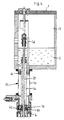
- Fig. 4 shows yet another embodiment of the device according to the invention in a schematic longitudinal section, wherein again the same parts are provided with the same reference numerals as before.
- the metering chamber 12 is attached to the underside of the storage container 1, wherein the storage container 1 can be designed as an annular bowl on which a number of metering chambers 12 are provided next to one another in the circumferential direction.
- the metering chamber 12 is designed as a cylindrical hollow body 44 which is flanged to the underside of the storage container 1 in the example shown. It carries a centering and sealing bell 6 for docking containers, not shown, to be filled.
- a container extension 46 is arranged in the form of a cylindrical tube piece, which is connected via its upper end to the liquid in the storage container 1 and therefore continuously is filled with liquid.
- the upper end of the metering chamber 12 is formed by a displacer 16, which seals the metering chamber from the liquid 2 in the reservoir 1.
- the container neck 46 is axially displaceably mounted and guided in the displacement body 16.
- the return gas tube 21, which connects the interior of a docked container with the gas space 3 of the storage container 1, is guided longitudinally axially through the container extension 46.
- the return gas tube 21 carries a valve body 47 in the region of its lower end, which fulfills a double function. On the one hand, this valve body 47 closes off the liquid outlet 20 of the metering chamber 12 towards the container to be filled. On the other hand, this valve body 47 forms the bottom of the storage container 1 in the region of the Container neck 46.
- the container neck 46 lies tightly on the valve body 47.
- the liquid passage 10 opens and the liquid 2 flows from the storage container 1 through the container neck 46 into the metering chamber 12, which concentrically surrounds the tube piece forming the container neck 46, the contained in the metering chamber Gas escapes through a gas line 48 into the gas space 3 of the storage container.
- the volume of the metering chamber 12 is adjusted as desired by moving the displacer 16 from the outside by means of the return gas line 40.
- the container extension 46 is lowered onto the valve body 47, so that the liquid passage 10 is closed.
- the return gas pipe 21 After prestressing the container to be filled through the return gas pipe 21, the return gas pipe is moved up together with the valve body 47 and the container extension 46, whereby the liquid outlet 20 is opened for filling the container.
- the liquid passage 10 remains closed.
- the gas displaced from the container to be filled during the filling process passes through the return gas pipe 21 into the gas space of the storage container 1.
- the return gas pipe 21 is lowered together with the container shoulder 46 in order to close the liquid outlet 20 again.
- This device also has the advantage that the metering chamber is filled with the liquid from below, with the liquid being prevented from bubbling up.
- the actuating means for adjusting the filling volume of the metering chamber 12 are led out of the storage container by adjusting the height of the displacer 16 upwards. This makes it possible to connect them to a controller that allows the
- displacement bodies can be adjusted individually or together centrally.
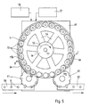
- Fig. 5 shows a schematic representation of a top view of a filling device according to the invention.
- the storage container 1 is rotatably mounted on a machine bed 49 about a vertical axis 51 in the direction of an arrow 52.
- the storage container 1 as already described in connection with the preceding figures, is designed as an annular bowl which, on its underside, carries a row of filling heads 53 in the circumferential direction next to one another, as described in the preceding Figures 1 to 4.
- the filling heads 53 are not visible per se in the top view of FIG. 5, but are indicated here by circles for better understanding.
- the ring bowl 1 is connected to a central supply space 56 surrounding the axis of rotation 51 via connections 54, which can be designed as tubes or channels.
- the reservoir is connected to a liquid reservoir 57 via a central feed line in the axis of the reservoir and corresponding rotary connections. Control means, not shown in the drawing, ensure that the liquid level in the reservoir 1 remains as constant as possible.
- a pressure source 58 which is also connected via rotary connections to a central supply line in the axis of rotation 51 of the storage container with the gas space of the storage container, serves to keep the pressure in the storage container constant at a desired value.
- the pressure source 58 contains carbon dioxide gas, so that the desired gas atmosphere in the gas space of the storage container 1 is maintained.
- the containers 8 to be filled are conveyed up on a conveyor line 59 and transferred to a feed star 61, which feeds them at the correct distance to the filling heads of the filling device passes where, as described in connection with FIGS. 1 to 4, they are docked for filling onto the centering and sealing bells 6 of the filling heads 53, where the filling process described then takes place.
- the filled containers 8 are taken over by a discharge star 62 and delivered to a discharge conveyor 63.
- the containers 8 are first biased after docking to the respective filling heads 53 when filling under counterpressure, for which purpose, according to FIG. 1, the pressure prevailing in the gas space 3 of the storage container is to be filled via the valve 29a Container 8 is created. This takes place in the peripheral section A / B of FIG. 5. A curve 64 is drawn in here for actuating the preload valve 29a, which acts accordingly on the preload valve 29a.
- the containers 8 are filled from the previously filled metering chambers, as has already been described above.
- further control cams of the type of control cams 11b and 64 are assigned to the peripheral section B / C of the storage container 1, but are not shown in the drawing.
- the containers 8 are relieved after the filling process, for which purpose the relief valve 31 is actuated with a control cam 66.
- the centering and sealing bell 6 is then lifted off the container again by means of the control cam 11b and transferred to the discharge star 62.
- the circumferential D / A cut the pre-dosing described above by filling the dosing chamber in the filling head, so that at A the new filling process can be initiated with a new container to be filled.
- control curves drawn in the drawing are only indicated schematically and are intended as exemplary embodiments. It goes without saying that the person skilled in the art will design and arrange these control curves in accordance with the requirements when implementing the invention.
- the passage valve 10 and the outlet valve 20 are actuated by moving a container part or the return gas pipe.
- this movable container part and / or the return gas pipe can be permanently installed.
- separately operable valves are provided in the liquid passage and / or in the liquid outlet.
- An example of such a valve is shown in FIG. 2 with the slide 38 which controls the passage openings 37.
Landscapes
- Filling Of Jars Or Cans And Processes For Cleaning And Sealing Jars (AREA)
- Vacuum Packaging (AREA)
- Basic Packing Technique (AREA)
Applications Claiming Priority (2)
| Application Number | Priority Date | Filing Date | Title |
|---|---|---|---|
| DE3928009 | 1989-08-24 | ||
| DE3928009A DE3928009A1 (de) | 1989-08-24 | 1989-08-24 | Vorrichtung zum fuellen von behaeltern |
Publications (2)
| Publication Number | Publication Date |
|---|---|
| EP0414075A1 true EP0414075A1 (fr) | 1991-02-27 |
| EP0414075B1 EP0414075B1 (fr) | 1993-11-18 |
Family
ID=6387806
Family Applications (1)
| Application Number | Title | Priority Date | Filing Date |
|---|---|---|---|
| EP90115441A Expired - Lifetime EP0414075B1 (fr) | 1989-08-24 | 1990-08-11 | Dispositif de remplissage de récipients |
Country Status (6)
| Country | Link |
|---|---|
| US (1) | US5125440A (fr) |
| EP (1) | EP0414075B1 (fr) |
| JP (1) | JPH03240607A (fr) |
| CA (1) | CA2023914A1 (fr) |
| DE (2) | DE3928009A1 (fr) |
| ES (1) | ES2046622T3 (fr) |
Cited By (5)
| Publication number | Priority date | Publication date | Assignee | Title |
|---|---|---|---|---|
| DE4312367A1 (de) * | 1993-04-16 | 1994-10-20 | Kronseder Maschf Krones | Vorrichtung zum portionsweisen Abfüllen von Flüssigkeiten in Flaschen, Dosen o. dgl. Behälter |
| DE19631971A1 (de) * | 1996-08-08 | 1998-02-12 | Ischwang Stefan Amadeus | Abfüllvorrichtung |
| US5865225A (en) * | 1993-04-16 | 1999-02-02 | Krones Ag Hermann Kronseder Maschinenfabrik | Rotating device for filling liquids in portions into bottles, cans or similar receptacles |
| DE19749738A1 (de) * | 1997-11-11 | 1999-05-20 | Mette Manfred | Füllorgan zur volumetrischen Getränkeabfüllung |
| EP3274260B1 (fr) * | 2015-03-23 | 2019-08-07 | Hema | Dispositif de dosage volumetrique pour machine de remplissage de recipients |
Families Citing this family (20)
| Publication number | Priority date | Publication date | Assignee | Title |
|---|---|---|---|---|
| DE4023998A1 (de) * | 1990-07-28 | 1992-01-30 | Alfill Getraenketechnik | Verfahren und vorrichtung zum abfuellen einer fluessigkeit in portionsbehaelter |
| US5234038A (en) * | 1991-09-27 | 1993-08-10 | Briggs & Stratton Corporation | Pour spout |
| US5628352A (en) * | 1992-07-24 | 1997-05-13 | Briggs & Stratton Corporation | Closable pour spout for fluid dispensing container |
| DE4303524C1 (de) * | 1993-02-06 | 1994-03-17 | Holstein & Kappert Maschf | Füllventil für eine Behälterfüllmaschine |
| US5848515A (en) * | 1995-08-11 | 1998-12-15 | Rossi & Catelli S.P.A. | Continuous-cycle sterile bottling plant |
| US6131624A (en) * | 1999-01-19 | 2000-10-17 | Crown Simplimatic Incorporated | Filling valve assembly |
| ATE240869T1 (de) * | 1999-02-02 | 2003-06-15 | Milena Stagni | Verfahren und vorrichtung zum dosieren von flüssigkeiten |
| US6354341B1 (en) | 1999-11-10 | 2002-03-12 | Shurflo Pump Manufacturing Co., Inc. | Rapid comestible fluid dispensing apparatus and method |
| US6443335B1 (en) | 1999-11-10 | 2002-09-03 | Shurflo Pump Manufacturing Company, Inc. | Rapid comestible fluid dispensing apparatus and method employing a diffuser |
| US20040232173A1 (en) * | 1999-11-10 | 2004-11-25 | Michael Saveliev | Rapid comestible fluid dispensing apparatus and method |
| US6360556B1 (en) | 1999-11-10 | 2002-03-26 | Shurflo Pump Manufacturing Company, Inc. | Apparatus and method for controlling fluid delivery temperature in a dispensing apparatus |
| US6354342B1 (en) | 1999-11-10 | 2002-03-12 | Shurflo Pump Manufacturing Company, Inc. | Hand-held rapid dispensing apparatus and method |
| US6449970B1 (en) | 1999-11-10 | 2002-09-17 | Shurflo Pump Manufacturing Company, Inc. | Refrigeration apparatus and method for a fluid dispensing device |
| US6662828B1 (en) * | 2001-05-22 | 2003-12-16 | Clifford W. Stover | Telescoping filling head |
| US6837282B2 (en) * | 2002-07-29 | 2005-01-04 | Ramon Navarro | Apparatus for filling containers with viscous liquid food products |
| DE20319789U1 (de) * | 2003-12-20 | 2004-02-26 | Khs Maschinen- Und Anlagenbau Ag | Füllmaschine mit separatem Rückgaskanal |
| JP4519146B2 (ja) * | 2006-01-27 | 2010-08-04 | 株式会社トパック | 充填包装装置及び充填包装方法 |
| ITPD20120028A1 (it) | 2012-02-07 | 2013-08-08 | Mbf Spa | Macchina riempitrice di contenitori con liquidi, e procedimento di riempimento di contenitori, in particolare mediante detta macchina riempitrice |
| DE102015116532A1 (de) * | 2015-09-30 | 2017-03-30 | Khs Gmbh | Verfahren sowie Behandlungsstation und Behandlungskopf zur Behandlung der Innenräume von KEGs sowie Dichtung zur Verwendung bei einer derartigen Behandlungsstation |
| US10479668B2 (en) | 2016-11-08 | 2019-11-19 | Pepsico, Inc. | Ambient filling system and method |
Citations (5)
| Publication number | Priority date | Publication date | Assignee | Title |
|---|---|---|---|---|
| US2162404A (en) * | 1936-11-18 | 1939-06-13 | Fmc Corp | Filling valve |
| US3334668A (en) * | 1965-08-30 | 1967-08-08 | Ex Cell O Corp | Filler for charging containers |
| DE1807542A1 (de) * | 1968-11-07 | 1970-06-11 | Bosch Gmbh Robert | Vorrichtung zum Abmessen und Abfuellen von Fluessigkeiten |
| FR2476626A1 (fr) * | 1980-02-25 | 1981-08-28 | Seitz Werke Gmbh | Appareil de remplissage proportionnel et a un niveau de recipients, tels que des bouteilles |
| FR2516495A1 (fr) * | 1981-11-19 | 1983-05-20 | Seitz Enzinger Noll Masch | Procede pour la mise sous pression de bouteilles dans une machine de remplissage, et dispositif de remplissage pour la mise en oeuvre de ce procede |
Family Cites Families (19)
| Publication number | Priority date | Publication date | Assignee | Title |
|---|---|---|---|---|
| US362393A (en) * | 1887-05-03 | Liquid-measure | ||
| US1523607A (en) * | 1919-03-15 | 1925-01-20 | American Can Co | Filling machine |
| US1763971A (en) * | 1927-10-21 | 1930-06-17 | Kantor James | Dispensing device |
| US2144628A (en) * | 1936-09-24 | 1939-01-24 | American Can Co | Container filling machine |
| US2466731A (en) * | 1940-09-07 | 1949-04-12 | American Can Co | Liquid filling machine with traveling measure |
| US2506125A (en) * | 1946-03-09 | 1950-05-02 | Lawrence M White | Measuring valve |
| US2761606A (en) * | 1954-07-16 | 1956-09-04 | Crown Cork & Seal Co | Filling machine |
| US3065887A (en) * | 1959-04-17 | 1962-11-27 | American Can Co | Adjustable measuring chamber for a dispenser |
| US3289712A (en) * | 1964-02-04 | 1966-12-06 | Chemetron Corp | Receptacle filling machines |
| US3464464A (en) * | 1965-10-23 | 1969-09-02 | Herman Laub | Balanced vacuum filler |
| US3626996A (en) * | 1970-04-08 | 1971-12-14 | Servi Tech Inc | Container-filling method and apparatus |
| US3830264A (en) * | 1972-03-27 | 1974-08-20 | Fmc Corp | Positive displacement filling machine |
| DE2257449A1 (de) * | 1972-11-23 | 1974-05-30 | Franz Crombach | Vorrichtung zum abfuellen von fluessigkeiten |
| US4043490A (en) * | 1975-04-10 | 1977-08-23 | Mckinney Harold D | Volumetric filling system apparatus |
| JPS5834358B2 (ja) * | 1976-05-28 | 1983-07-26 | 三菱重工業株式会社 | 壜詰方法 |
| DE2832325A1 (de) * | 1978-07-22 | 1980-01-31 | Noll Maschfab Gmbh | Ventilfuellorgan fuer kohlensaeurehaltige getraenke |
| US4398575A (en) * | 1981-06-26 | 1983-08-16 | Barry-Wehmiller Company | Filler tube with check valve for container filling devices |
| DE3429314C2 (de) * | 1984-08-09 | 1986-08-28 | Krones Ag Hermann Kronseder Maschinenfabrik, 8402 Neutraubling | Verfahren und Vorrichtung zum Entfernen von Spanngas und Flüssigkeit aus Gefäßen |
| IT1200221B (it) * | 1986-10-03 | 1989-01-05 | Simonazzi Spa A & L | Equipaggiamento per la predeterminazione, la regolazione simultanea e la taratura micrometrica individuale di esatte quantita' di liquido per erogare in processi di riempimento a gravita' |
-
1989
- 1989-08-24 DE DE3928009A patent/DE3928009A1/de not_active Withdrawn
-
1990
- 1990-08-11 EP EP90115441A patent/EP0414075B1/fr not_active Expired - Lifetime
- 1990-08-11 ES ES199090115441T patent/ES2046622T3/es not_active Expired - Lifetime
- 1990-08-11 DE DE90115441T patent/DE59003519D1/de not_active Expired - Fee Related
- 1990-08-15 US US07/568,273 patent/US5125440A/en not_active Expired - Fee Related
- 1990-08-22 JP JP2219145A patent/JPH03240607A/ja active Pending
- 1990-08-23 CA CA002023914A patent/CA2023914A1/fr not_active Abandoned
Patent Citations (5)
| Publication number | Priority date | Publication date | Assignee | Title |
|---|---|---|---|---|
| US2162404A (en) * | 1936-11-18 | 1939-06-13 | Fmc Corp | Filling valve |
| US3334668A (en) * | 1965-08-30 | 1967-08-08 | Ex Cell O Corp | Filler for charging containers |
| DE1807542A1 (de) * | 1968-11-07 | 1970-06-11 | Bosch Gmbh Robert | Vorrichtung zum Abmessen und Abfuellen von Fluessigkeiten |
| FR2476626A1 (fr) * | 1980-02-25 | 1981-08-28 | Seitz Werke Gmbh | Appareil de remplissage proportionnel et a un niveau de recipients, tels que des bouteilles |
| FR2516495A1 (fr) * | 1981-11-19 | 1983-05-20 | Seitz Enzinger Noll Masch | Procede pour la mise sous pression de bouteilles dans une machine de remplissage, et dispositif de remplissage pour la mise en oeuvre de ce procede |
Cited By (8)
| Publication number | Priority date | Publication date | Assignee | Title |
|---|---|---|---|---|
| DE4312367A1 (de) * | 1993-04-16 | 1994-10-20 | Kronseder Maschf Krones | Vorrichtung zum portionsweisen Abfüllen von Flüssigkeiten in Flaschen, Dosen o. dgl. Behälter |
| US5865225A (en) * | 1993-04-16 | 1999-02-02 | Krones Ag Hermann Kronseder Maschinenfabrik | Rotating device for filling liquids in portions into bottles, cans or similar receptacles |
| DE19631971A1 (de) * | 1996-08-08 | 1998-02-12 | Ischwang Stefan Amadeus | Abfüllvorrichtung |
| DE19631971C2 (de) * | 1996-08-08 | 1998-10-01 | Ischwang Stefan Amadeus | Abfüllvorrichtung |
| DE19749738A1 (de) * | 1997-11-11 | 1999-05-20 | Mette Manfred | Füllorgan zur volumetrischen Getränkeabfüllung |
| WO1999024350A1 (fr) * | 1997-11-11 | 1999-05-20 | Manfred Mette | Dispositif de remplissage pour l'embouteillage volumetrique de boissons |
| EP3274260B1 (fr) * | 2015-03-23 | 2019-08-07 | Hema | Dispositif de dosage volumetrique pour machine de remplissage de recipients |
| US10926897B2 (en) | 2015-03-23 | 2021-02-23 | Hema | Volumetric metering device for container filling machine |
Also Published As
| Publication number | Publication date |
|---|---|
| CA2023914A1 (fr) | 1991-02-25 |
| US5125440A (en) | 1992-06-30 |
| EP0414075B1 (fr) | 1993-11-18 |
| DE59003519D1 (de) | 1993-12-23 |
| ES2046622T3 (es) | 1994-02-01 |
| JPH03240607A (ja) | 1991-10-28 |
| DE3928009A1 (de) | 1991-02-28 |
Similar Documents
| Publication | Publication Date | Title |
|---|---|---|
| EP0414075B1 (fr) | Dispositif de remplissage de récipients | |
| DE3825093C2 (de) | Verfahren und Vorrichtung zum Füllen von Flaschen oder dgl. in Gegendruckfüllmaschinen | |
| DE10359492B3 (de) | Füllelement für eine Füllmaschine | |
| DE2251331C3 (de) | Verfahren zum Abfeilen einer kohlensäurehaltigen Flüssigkeit und Vorrichtung zur Durchführung des Verfahrens | |
| DE3431107C2 (de) | Verfahren und Vorrichtung zum Füllen von Flaschen o.dgl. | |
| DE2317504A1 (de) | Vorrichtung zum abfuellen fluessiger oder fliessfaehiger materialien aus einem vorratstank in einzelne behaelter, wie dosen oder kanister | |
| EP0470398A1 (fr) | Procédé et dispositif de remplissage de récipients calibrés de liquides | |
| DE2340613A1 (de) | Verfahren und einrichtung zum fuellen von behaeltern mit einer gas enthaltenden fluessigkeit | |
| DE2002060C3 (de) | Füllrohrloses Füllelement für Gegendruck-Füllmaschinen in Ein- oder Mehrkammer-Bauweise | |
| DE2800972B2 (de) | Behälterfüllorgan mit Kolben/Zylinder-Hubanordnung | |
| EP1655264B1 (fr) | Machine de remplissage du type à carrousel | |
| DE2808345A1 (de) | Behaelterfuellorgan mit hebbarem rueckluftrohr | |
| DE3325338A1 (de) | Fuelleinrichtung fuer stillgetraenke | |
| DE2454888A1 (de) | Flaschenfuellmaschine | |
| DE3202655C1 (de) | Verfahren und Vorrichtung zum Hinzugeben einer vorgegebenen Menge einer zweiten Fluessigkeit(Dosierfluessigkeit)zu einer in einem Behaelter befindlichen ersten Fluessigkeit | |
| DE2947035C2 (de) | Füllelement für Gegendruck-Gefäßfüllmaschine | |
| DE2127015B2 (de) | Vorrichtung zum selbsttätigen Füllen mit hoher Füllgeschwindigkeit von Behälter mit einem Kohlensäure enthaltenden Getränk o.dgl. Produkt | |
| DE2123865A1 (de) | Füllelement | |
| DE3590070C2 (de) | Fl}ssigkeitseinf}llvorrichtung | |
| DE1047657B (de) | Rotierender Gegendruckfueller | |
| DE2404315C2 (de) | Heb- und senkbarer Füllkopf für Vorrichtungen zum selbsttätigen Füllen mit hoher Füllgeschwindigkeit von Dosen oder Flaschen oder dgl. Behälter mit einem Kohlensäure enthaltenden Getränk | |
| DE2848604C2 (de) | Vorrichtung zum Abfüllen von Getränken | |
| DE4312367A1 (de) | Vorrichtung zum portionsweisen Abfüllen von Flüssigkeiten in Flaschen, Dosen o. dgl. Behälter | |
| DE19631971C2 (de) | Abfüllvorrichtung | |
| DE3515769A1 (de) | Abfuellvorrichtung fuer bier oder dergleichen fluessigkeiten |
Legal Events
| Date | Code | Title | Description |
|---|---|---|---|
| PUAI | Public reference made under article 153(3) epc to a published international application that has entered the european phase |
Free format text: ORIGINAL CODE: 0009012 |
|
| AK | Designated contracting states |
Kind code of ref document: A1 Designated state(s): BE DE ES FR GB IT NL |
|
| 17P | Request for examination filed |
Effective date: 19910813 |
|
| 17Q | First examination report despatched |
Effective date: 19920227 |
|
| ITF | It: translation for a ep patent filed | ||
| GRAA | (expected) grant |
Free format text: ORIGINAL CODE: 0009210 |
|
| AK | Designated contracting states |
Kind code of ref document: B1 Designated state(s): BE DE ES FR GB IT NL |
|
| REF | Corresponds to: |
Ref document number: 59003519 Country of ref document: DE Date of ref document: 19931223 |
|
| GBT | Gb: translation of ep patent filed (gb section 77(6)(a)/1977) |
Effective date: 19931214 |
|
| ET | Fr: translation filed | ||
| REG | Reference to a national code |
Ref country code: ES Ref legal event code: FG2A Ref document number: 2046622 Country of ref document: ES Kind code of ref document: T3 |
|
| PGFP | Annual fee paid to national office [announced via postgrant information from national office to epo] |
Ref country code: GB Payment date: 19940720 Year of fee payment: 5 |
|
| PGFP | Annual fee paid to national office [announced via postgrant information from national office to epo] |
Ref country code: ES Payment date: 19940801 Year of fee payment: 5 |
|
| PGFP | Annual fee paid to national office [announced via postgrant information from national office to epo] |
Ref country code: FR Payment date: 19940802 Year of fee payment: 5 |
|
| PGFP | Annual fee paid to national office [announced via postgrant information from national office to epo] |
Ref country code: NL Payment date: 19940831 Year of fee payment: 5 |
|
| PGFP | Annual fee paid to national office [announced via postgrant information from national office to epo] |
Ref country code: BE Payment date: 19940905 Year of fee payment: 5 |
|
| PGFP | Annual fee paid to national office [announced via postgrant information from national office to epo] |
Ref country code: DE Payment date: 19940919 Year of fee payment: 5 |
|
| PLBE | No opposition filed within time limit |
Free format text: ORIGINAL CODE: 0009261 |
|
| STAA | Information on the status of an ep patent application or granted ep patent |
Free format text: STATUS: NO OPPOSITION FILED WITHIN TIME LIMIT |
|
| 26N | No opposition filed | ||
| PG25 | Lapsed in a contracting state [announced via postgrant information from national office to epo] |
Ref country code: GB Effective date: 19950811 |
|
| PG25 | Lapsed in a contracting state [announced via postgrant information from national office to epo] |
Ref country code: ES Free format text: LAPSE BECAUSE OF THE APPLICANT RENOUNCES Effective date: 19950812 |
|
| PG25 | Lapsed in a contracting state [announced via postgrant information from national office to epo] |
Ref country code: BE Effective date: 19950831 |
|
| BERE | Be: lapsed |
Owner name: ALFILL GETRANKETECHNIK G.M.B.H. Effective date: 19950831 |
|
| PG25 | Lapsed in a contracting state [announced via postgrant information from national office to epo] |
Ref country code: NL Effective date: 19960301 |
|
| GBPC | Gb: european patent ceased through non-payment of renewal fee |
Effective date: 19950811 |
|
| PG25 | Lapsed in a contracting state [announced via postgrant information from national office to epo] |
Ref country code: FR Effective date: 19960430 |
|
| NLV4 | Nl: lapsed or anulled due to non-payment of the annual fee |
Effective date: 19960301 |
|
| PG25 | Lapsed in a contracting state [announced via postgrant information from national office to epo] |
Ref country code: DE Effective date: 19960501 |
|
| REG | Reference to a national code |
Ref country code: FR Ref legal event code: ST |
|
| REG | Reference to a national code |
Ref country code: ES Ref legal event code: FD2A Effective date: 19991007 |
|
| PG25 | Lapsed in a contracting state [announced via postgrant information from national office to epo] |
Ref country code: IT Free format text: LAPSE BECAUSE OF NON-PAYMENT OF DUE FEES;WARNING: LAPSES OF ITALIAN PATENTS WITH EFFECTIVE DATE BEFORE 2007 MAY HAVE OCCURRED AT ANY TIME BEFORE 2007. THE CORRECT EFFECTIVE DATE MAY BE DIFFERENT FROM THE ONE RECORDED. Effective date: 20050811 |