EP0414090A2 - Appareil de développement - Google Patents
Appareil de développement Download PDFInfo
- Publication number
- EP0414090A2 EP0414090A2 EP90115506A EP90115506A EP0414090A2 EP 0414090 A2 EP0414090 A2 EP 0414090A2 EP 90115506 A EP90115506 A EP 90115506A EP 90115506 A EP90115506 A EP 90115506A EP 0414090 A2 EP0414090 A2 EP 0414090A2
- Authority
- EP
- European Patent Office
- Prior art keywords
- hub
- column
- film
- plate
- arm
- Prior art date
- Legal status (The legal status is an assumption and is not a legal conclusion. Google has not performed a legal analysis and makes no representation as to the accuracy of the status listed.)
- Withdrawn
Links
Images




Classifications
-
- G—PHYSICS
- G03—PHOTOGRAPHY; CINEMATOGRAPHY; ANALOGOUS TECHNIQUES USING WAVES OTHER THAN OPTICAL WAVES; ELECTROGRAPHY; HOLOGRAPHY
- G03D—APPARATUS FOR PROCESSING EXPOSED PHOTOGRAPHIC MATERIALS; ACCESSORIES THEREFOR
- G03D3/00—Liquid processing apparatus involving immersion; Washing apparatus involving immersion
- G03D3/08—Liquid processing apparatus involving immersion; Washing apparatus involving immersion having progressive mechanical movement of exposed material
- G03D3/10—Liquid processing apparatus involving immersion; Washing apparatus involving immersion having progressive mechanical movement of exposed material for plates, films, or prints held individually
Definitions
- This invention relates to photographic film developing apparatus having a film holder which is moved in a circular path to a series of processing stations.
- the film holder is indexed from station to station and at the respective stations in lowered into and raised out of the station.
- Photographic film apparatus of the general type described above are known from U.S. Patent No. 3,412,667, granted November 26, 1968, for example.
- Such apparatus has a series of processing tanks arranged in a circular manner and containing various film processing solutions.
- Film is placed in a film holder and attached to the periphery of a rotatable turntable mounted on a vertically slideable shaft.
- a motor driven crank lifts and rotates the shaft to transport the film holders to the tanks.
- the present invention is intended for the processing of intraoral dental X-ray films, in which it is important that the processing be done accurately and with a minimum of human intervention.
- a plurality of processing stations are disposed concentrically about a vertical axis at which is located a column having an external spiral groove which ends a short distance above the lower end of the column and a short distance below the upper end of the column.
- the stations include stations for loading film holders into the apparatus, developing, fixing, washing, preliminary spinning, final spinning with drying, and unloading the film holders from the apparatus.
- the column is rotated in both clockwise and counterclockwise directions to move the film holders downwardly or upwardly.
- the film holders are suspended from arms which project radially from an annular hub which rides up and down on the column.
- a pin carried by the hub rides in the groove in the column to cause upward and downward movement of the hub and associated film holders as the column rotates.
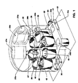
- a generally circular housing 20 the light tight cover for which is not shown.
- the housing and the apparatus within rest on a support 21.
- Extending outwardly from the housing at the loading station 22 is a loading platform 23 which has storage container openings 23a for film to be processed and for the film coverings which are removed before loading.
- the loading station 22 then, in a counterclockwise direction, a developing or activating station 25, a fixing station 26, a washing station 27, a liquid removal station 28, a drying station 29, and an unloading station 30.
- the treating stations comprise cylindrical housings which, in the case of the stations 25, 26 and 27, comprise tanks open at their upper ends, for holding the appropriate liquids.
- each of these three tanks are reservoirs 25a, 26a and 27a for the respective liquids. These reservoirs communicate with the respective tanks by conduits 25b, 26b and 27b, using gravity feed controlled by valves (not shown) in the drain lines for the tanks. Receptacles for the used liquids are located below the tanks, one such being indicated at 31. Fresh liquid feed is by means of “chicken feeder” arrangements which operate to maintain the liquid levels in the respective tanks as liquids are drained from them. One drain line is shown at 31a.
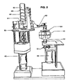
- a film holder 43 is shown (in a non-detailed manner) at one of the spinning stations. Details of the holder are shown in Figs .7, 8, and 12. The general arrangement of the mechanical parts is well shown in Fig. 2, although details are better shown in other Figs. Two motors are shown, motor 45, preferable a stepping motor, for rotating column 40, and motor 46 for driving one of the spinning operations. The upper end of a spiral groove 48 on the periphery of column 40 is seen at 49.
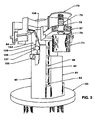
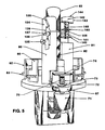
- Figs. 4 and 5 show more detail of the construction of hub 41 and the arms 42 which support the film carriers.
- Hub 41 comprises a central portion 60 having a central bore which fits snugly but slideably about column 40. Seven narrow arms 61 spaced at equal angles about the central portion 60, extend radially from central hub portion 60.
- the outer end of each arm terminates in an enlarged portion 62 having a peripheral surface which is vertical when viewed from the side and convex when viewed from above. Near the lower end of this surface is an outwardly extending rib 63, and below that, on the inwardly facing surface of portion 62, is an inwardly extending pin 64 located near the left end portion 62. Pin 64 cooperates with an escapement mechanism to be described below.
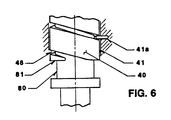
- Another pin 41a (Fig. 6) extends into the bore of the central portion 60 of the hub and rides in spiral groove 48 on the outer periphery of column 40.
- An intermediate arm member 65 has an inwardly facing concave surface and a groove 66 to mate with the hub portion 62 and rib 63, and is attached to portion 62 by screws 65a or other suitable means.
- Member 65 in turn, carries an outer arm member 67 which is bolted thereto at 68.
- Attachment 68 may be adjustable, if desired, to provide for exact initial positioning of member 67.
- Near the outer end of member 67 is a bore in which is mounted a plastic or other bearing 69 into which extends the upper end of a shaft 70.
- a magnet 71 is attached to the lower end of shaft 70.
- the upper portion of shaft 70 extends slideably and rotatably through bearing 69 and is prevented from falling out of the bearing by a retainer 72 attached to the shaft above the upper surface of arm member 67.
- a coil spring 73 surrounds the upper end portion of shaft 70. At its lower end the spring abuts against retainer 72, and at its upper end abuts against a bracket 74 attached to the arm member 67 and spaced above its upper surface. In the position shown in Fig. 4, the upper end of shaft 69 is spaced from bracket 74, permitting shaft 69 to move upwardly a short distance against the bias provided by spring 73. Arm portions 65 and 67 could of course be integral, depending upon manufacturing preferences.
- column 40 has a reduced diameter section 80 near its lower end, forming a shoulder 81 at the upper end of the reduced diameter portion.
- the lower end of groove 48 opens onto shoulder 81 as shown in Fig. 6 and thus forms a discontinuity in the shoulder.
- a coil compression spring 82 is mounted on platform 50 around column 40 so as to be compressed by the bottom surface of hub 60 when the hub reaches its lowermost position.
- sub 41 has an inwardly extending pin 41a which rides in groove 48.
- the pin rides down the slot, carrying the hub with it, the hub being restrained against rotation by means to be described below.
- motor 45 is operated in each direction for a short distance, causing pin 41a to move in the lower end of groove 48.
- the column continues rotating after the pin leaves the lower end of the groove.
- base 50 supports two vertically extending guide members 90 and 91 which are spaced a short distance apart to provide a guideway 92.
- the relatively narrow arms 61 have a width which is slightly less than the width of guideway 92.
- Clockwise rotation of column 40 takes place only when one of these arms 61 is aligned with the guideway and can move downwardly in the guideway as such rotation moves pin 41a downwardly in groove 48 and thereby moves hub 41 downwardly until the pin escapes from the lower end of the groove, as discussed above.
- Upward movement of hub 41 is achieved by reversing the rotation of the column to counterclockwise. This causes pin 41a to reenter groove 48 and move upward in the groove, carrying the hub and arms 42 with it.
- Figs. 7 and 8 show one embodiment of the film holder, a preferred embodiment being shown in Fig. 12. Both embodiments are novel and basically similar.
- the holder comprises a cylinder 90 which is open at the bottom and has a series of spaced slots 91 extending from its upper edge part way down the height of the cylinder.
- a circular plate 92 of greater diameter than the cylinder is attached to the upper edge of the cylinder and is concentric therewith.
- Plate 92 has a series of slots 93, each of which communicates with one of the slots 91. Other portions of plate 92 may be removed to facilitate movement of liquids and air though the holder.
- shaft 54 Extending axially through and attached to plate 92 is shaft 54 which terminates at its lower end in a pointed or frustoconical portion 53 as referred to above.
- the lower end of the shaft is level with or slightly above the plane of the lower end of cylinder 90.
- Slots 93 are of a length slightly greater than the film to be received in the slot, and these slots are canted from radii of shaft 54.
- Magnetic material such as a magnet 71a, is attached to the upper end of shaft 54.
- a second or upper circular plate 94 generally similar to plate 92, is moveably but snugly mounted on shaft 54.
- Plate 94 has a series of slots 95 corresponding in number, size, shape and orientation, to slots 93. As shown at 95a in Fig. 12, the edges of slots 95 are preferably sloping to facilitate loading film into these slots.
- Plate 94 has a notch 94a communicating with its central opening through which the shaft extends (Fig. 7). In one embodiment, this notch cooperates with a key 96 fixed to shaft 54, the key having an enlarged lower portion 96a which defines the limit of downward movement of plate 94.
- the cooperation of key 96 and notch 94a limits rotational movement of upper plate 94 relative to shaft 54 and lower plate 92, and in one embodiment defines the processing position of the upper plate, in which position its slots 94 are offset from slots 93 in the lower plate.
- the key and notch 94a define the loading position of the upper plate, with the slots of the two plates aligned.
- the magnetic part 71a is of greater diameter than shaft 54 and an "O" ring 94b of a high friction material, such as rubber, is fitted tightly around the shaft and snugly against the lower surface of magnetic part 71a.
- upper plate 94 is disengaged from the key 96, is rotated enough to move its slots out of alignment with slots 93 in the lower disc, and is pressed firmly against "O" ring 94b, its frictional engagement with which, combined with its snug fit on shaft 54, holds the upper plate in this upper position during processing.
- upper plate 94 is moved to a loading position ( Figure 7) with its slots aligned with the slots in the lower plate. It is then moved to a processing position ( Figure 8).
- upper plate 94 is positioned above the level of liquid in the processing tanks when the holder is lowered into and reciprocated in the tanks. This reduces the amount of liquid carry over from one station to the next. In this elevated position on shaft 54, upper plate 94 is still close enough to the upper edges of film in the holder to prevent film from escaping the holder during processing.
- a second key may be used if desired to define the loading position.
- the plate is rotated to engage key 96 with the notch, and plate 94 is slid downwardly until stopped by enlarged portion 96a of key 96.
- the bottom surface of plate 94 is spaced slightly above the upper edges of film that has been loaded through slots 95 into slots 93 and 91. For unloading, the loading procedure is reversed.
- the enclosure for the various stations is light tight so that the processor can operate without the entire room being dark, room darkness being required only during loading of the device. Depending upon the sensitivity of the film, an appropriate safelight may of course be used, rather than total darkness.
- the device is constructed with a light tight closure at the loading station, so that once the loading into the processor is accomplished and the loading opening closed, room lights may be on.
- a loading opening 100 is provided in housing 20 at the loading station 22.
- This opening is closed by an upper door 101 and a lower door 102, both of which slide up and down in guideways 103 located on each lateral side of the loading opening.
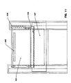
- the lower edge of upper door 101 and the upper edge of lower door 102 have an interlocking, light tight cooperation as shown in cross section at 104 in Fig. 10.
- the upper door has an operating handle 105 extending toward the operator. When this handle is pushed downwardly by the operator, its bottom surface contacts the upper end of lower door 102 during the final portion of the downward movement of the handle, and pushes the lower door down to open position.
- a housing 110 segregates the station at the sides and bottom from the rest of the stations.
- Bottom wall 110a of this housing supports an upwardly extending cylindrical guide 111 which contains a coil spring 112.
- Fitting about guide 111 and telescoping with it is a larger cylinder 113 attached to the underside of a flat loading platform 114 of circular configuration which is biased upwardly by the pressure of spring 112 against the bottom surface of loading platform 114.
- Loading platform 114 has a vertical wall 115 around its rear portion to define a horizontal surface configuration matching the horizontal cross section of cylinder 90 of the film holder.
- One of the arms 42 is indicated in a non-detailed manner with its magnet 71 aligned with the center of the film holder position on platform 114.
- Wall 115 flares at the front as shown at 115a to facilitate sliding a film holder onto loading platform 114.
- Wall 115 has along its upper edge an outwardly extending flange 116 and has lateral extensions 117 on each side. These extensions are positioned for engagement by two rearwardly projecting arms 118 located on the rear side of upper door 101, when the door is depressed. These arms are near the upper edge of door 101.
- the unloading station 30 is not shown in detail in the drawings. It consists merely of a pair of springs or other deflectors positioned to engage the upper surface of film holder plate 94 on opposite sides of shaft 54 when arm 67 carrying the holder loaded with processed film is rotated to a position over unloading station 30. These springs are positioned at an angle to the path of travel of the film holder and are sufficiently stiff to loosen and detach the film holder magnetic part 71a from arm magnet 71. The film holder then drops into a chute which conveys it to the operator for unloading of film and reuse of the film holder.
- One form of escapement mechanism comprises two devices mounted near the upper ends of the two uprights 90 and 91 to define the stop position of hub 41, arms 42 and film holders 43.
- upright guide members 90 and 91 are spaced apart a distance slightly greater than the width of the narrow arm portions 61 so as to provide a guideway 92 for those arm portions.
- These uprights are spaced a short distance from column 40 to provide room for the central portion of hub 41 and coil spring 82 which encircles the lower end of the column and which, as explained above, bears against base 50 and the bottom surface of hub 41 when the latter is at its lowermost position.
- Upright guide member 90 carries on its outside surface, blocking detent means comprising an arm 134 which pivots about hinge pin 135 mounted on that upright. The pin extends radially of the column. Arm 134 has an arcuate slot 136 into which extends a movement limiting pin 137 fixed to upright 90. At its upper end arm 134 has an integral flange 138 extending away from column 40. Flange 138 is slanted with respect to the axis of column 41 in the normal or rest position of arm 134. A spring 139 biases arm 134 to this normal position.
- Flange 138 extends a sufficient distance from the axis of column 40 to position its rear surface in the path of movement of engaging means in the form of pins 64 when hub 41, at the limit of its upward movement, rotates counterclockwise. In the normal position of arm 134, flange 138 does not interfere with the pin 64 on a radial arm 64 moving upwardly with the hub along the column. It should be pointed out that in Fig. 3, hub 41 is not quite at the limit of its upward movement. When it reaches that limit, the lower edges of arm portions 61 are higher than the upper ends of uprights 90 and 91.
- the upper end of upright 91 carries a bracket with two spaced arms 140 which slideably guide an elongated post 141 which is vertically moveable relative to the bracket.
- the upper end of the post carries an elongated blocking member 142 which has a vertical surface 143 at its counterclockwise end, while its upper surface 144 slopes upwardly to the upper end of surface 143.
- a coil spring 145 surrounds post 141 and urges it upwardly, this movement being limited by a pin 146 carried by the post and engaging one of the arms 140.
- Surface 144 is normally at an elevation such that when an arm 61 moves up and out of guideway 92 and then moves counterclockwise to the next station, the pin 64 on that arm slides along surface 144 and forces post 140 downwardly against the spring bias until the pin clears surface 144. At that point spring 145 restores post 140 to its uppermost, normal position and pin 64 is in contact with vertical surface 143 so that surface 143 blocks return clockwise movement of the arm 61 by blocking such movement of the pin 64 carried by the arm.
- the column rotation is changed from counterclockwise to clockwise in order to lower the hub and attached arms, the arms still being above the upper end of guideway 92, the arms cannot move in a clockwise direction with the column because such movement is blocked by member 142.
- Fig. 13 shows a preferred form of escapement mechanism.
- the mechanism just described is intended for operation whith a DC motor which can drive column 40 both clockwise and counterclockwise. If such motor is not a stepper motor, the mechanism just described is appropriate.
- column 40 can be rotated in both directions but with highly accurate control of the rotational position of the column.
- the stepping is set to rotate the column counterclockwise by the exact number of steps to move one arm 42 from a position over guideway 92 to the next station and bring the succeeding arm into alignment with the guideway.
- both mechanisms 135-139 and 140-146 shown in Fig. 5 are eliminated and a single escapement mechanism (shown in Fig. 13) is used to prevent reverse (clockwise) movement of the hub once an arm is moved into alignment with the guideway, but while it is still above the upper end of the guideway.
- the device of Fig. 13 comprises a pivoted member 150, similar to member 134 of Fig. 5, with a pivotal mounting 151 on guide 90.
- Guide 91 is not shown in this Fig. but is of course needed to provide the guideway 92 in cooperation with guide 90.
- Member 150 has an arcuate slot 152 through which extends a post 153 attached to guide 90.
- a spring 154 is mounted about post 153 and operates, as did the spring 139 in Fig. 5, to rotate member 150 to the limit of its counterclockwise movement as permitted by slot 152 and pin 153.
- member 150 On the upper end of member 150 is a blocking element 155 similar in function to member 142 in Fig. 5, but of different configuration.
- the right hand surface 156 of member 155 is normally vertically disposed and in line with the right hand edge of guide 90. In that position, the upper end of that surface blocks clockwise movement of an arm 42 aligned with guideway 92.
- the upper surface of member 155 has two portions.
- the clockwise portion 157 is normally horizontal and below the level of the bottom surfaces of arms 42 when they are in their uppermost position. Thus the arms can move freely over that portion of member 155 when in that elevated position.
- Surface portion 157 merges in a counterclockwise direction into an upwardly sloping surface portion 158.
- the slope of portion 158 is such that its end at the upper end of surface 156 lies above the path of travel of the lower surface of arms 42.
- An optical switch 160 tells the control apparatus that the above described operation has been completed so that the motor can reverse the rotation of column 40 to lower the hub and arms for the next processing operation.
- the optical switch comprises a sender and receiver located in spaced relation on guide 90 just below pivot 151. One of these switch parts is shown at 161; the other is closer to guide 90.
- the light beam across the gap between the two switch parts is interrupted by a downwardly extending tab 162 on member 150 below pivot 151.
- Fig. 13 shows this tab in its normal position clear of the gap between the switch parts, but the system can be set up to make the beam interrupting position the normal position of the tab.
- the operator working in the dark or with a safelight, strips the covering from the exposed intraoral x-ray films and loads the film into a carrier.
- the plates of the carrier are shown in Fig.7 in loading position with their slots 93 and 95 aligned.
- upper plate 94 is rotated 20 degrees about shaft 54 and moved to the processing position as explained above, with the slots 95 in the upper plate out of alignment with the slots 93 in the lower plate so that the films cannot move upwardly out of slots 93 until the upper plate is restored to its loading position.
- spring 112 moves the loading platform and film holder upwardly to its normal, elevated position to engage the magnetic material 71a on the upper end of film holder shaft 54 with magnet 71 carried by the arm 61, 65, 67 positioned above the loading station.
- the operator will of course have a number of film holders, and as one is loaded and the processing of its film begun, another can be loaded and placed in the apparatus for movement up to the next (clockwise) radial arm following the one just started through the processing sequence.
- the apparatus is operated by a microprocessor (mP), not shown, which receives a signal sent by closing of the loading doors, whereupon the mP starts the process by taking the processor out of standby.
- the mP starts a stepping motor 45 of Fig. 2, which rotates column 40, initially rotating the column counterclockwise to raise hub 41 and the seven arms which extend radially from the hub at angular positions spaced by 51.43 degrees. This rotation continues for 3.125 turns of column 40, which moves hub 41 to its uppermost position.
- the motor then rotates the column counterclockwise an additional 51.43 degrees, hub 41 moving with it due to the engagement of pin 41a with the upper end of groove 48 in the column.
- the mP then rotates column 40 clockwise (viewed from above) to move pin 41a downwardly in groove 48, carrying with it hub 41 and the seven arms carried by the hub.
- the film holder just loaded enters the developing solution and is agitated by the limited vertical reciprocation of hub 41 and its arms caused by pin 41a alternately entering and leaving the lower end of groove 48 and the upward bias of spring 82 against the bottom surface of hub 41.
- Each arm moves downwardly with hub 41, the arm located above the guideway moving downwardly into the guideway to the loading station.
- the mP When the mP has timed out this step, it again directs the motor to rotate the column counterclockwise to raise the hub and arms, and then to effect the 51.43 degrees counterclockwise rotation of the hub and arms.
- Optical switch 160 insures that the stepping motor does not start the next clockwise rotation of the column until an arm has moved past the escapement mechanism shown in Fig. 13. Clockwise rotation of the column lowers the hub and arms again for the next step in the processing. All of the cycles have the same duration. This permits all seven arms to carry film holders, if desired, or random arms to carry film holders.
- the film being processed is moved from the developing station to a fixing station, then to a wash bath. It is then moved to a spin station where it is spun rapidly, for example at 2000 rpm, to remove excess moisture and thereby reduce drying time.
- the mP operates the appropriate spin motor only when it knows a film holder is at a spin station. In the drying station which follows the spin station, hot air is blown on the film while the film holder is rotated at about 200 rpm. Again, the mP knows when a loaded film holder is in the drying station and turns on and off the spin motor, air heater and blower as appropriate.
- the carrier After the drying cycle the carrier is moved to the unloading station where the magnetic connection is broken, permitting the film holder with the completely processed film to fall into a chute and out to the operator. If there is no other film loaded holder in the apparatus, the mP switches the machine to standby, otherwise it will continue cycling until all film in the apparatus has been processed and delivered to the unloading station.
- the developer and fixer solutions and the wash water are in tanks open at their upper ends and fed by containers as indicated at 25a, 26a, and 27a in Fig. 1.
- the containers are connected to feed the tanks by a "chicken feeder" arrangement which automatically maintains the liquids in the tanks at a proper level.
- the wash water may be provided by a connection to an external water supply, with a solenoid valves operated by the mP, controlling feed to the wash water tank and drain. This option would require an external drain for the used wash water.
- Auto-replenishment of the liquids is controlled by the mP, which keeps track of the number of film holders run through the apparatus and operates drain valves for the respective tanks when appropriate.
- the "chicken feeder" arrangement then tops off the tanks. Also, every time the processor is powered up, a small amount of developer and fixer will be automatically drained off and replaced by fresh solution. Automatic drain off and replenishment may also be achieved by providing in each liquid tank a valve which is contacted by a portion of the film holder when it enters the tank to release a small amount of liquid from the tank.
- Expended solution is collected in a waste tank inside the processor or external to it.
- the mP can also determine when the waste tank needs to be emptied. Electrical probes contacted by the solutions' reaching a predetermined level can signal the mP or light a lamp to alert the operator to dump solution from the waste tank, and the apparatus can be automatically disabled until this has been done. Alternating current is used with the probes to reduce plating and erosion.
- the developing and fixing solutions are such that the film is treated for the same period in each solution, and is, of course, washed, spun and dried for the same period.
- the developer and fixer tanks sit on an electric heater such as a silicone pad heater and the temperature of the solutions is sensed by a thermistor located near the pad.
- the thermistor signal is compared to a desired temperature signal by a comparator.
- the comparator drives an optocoupler which turns on and off a triac which controls the pads and thus the temperature of the solutions.
Landscapes
- Physics & Mathematics (AREA)
- General Physics & Mathematics (AREA)
- Photographic Processing Devices Using Wet Methods (AREA)
- Photographic Developing Apparatuses (AREA)
Applications Claiming Priority (2)
| Application Number | Priority Date | Filing Date | Title |
|---|---|---|---|
| US07/397,147 US5005036A (en) | 1989-08-22 | 1989-08-22 | Processing apparatus |
| US397147 | 1989-08-22 |
Publications (2)
| Publication Number | Publication Date |
|---|---|
| EP0414090A2 true EP0414090A2 (fr) | 1991-02-27 |
| EP0414090A3 EP0414090A3 (en) | 1991-12-11 |
Family
ID=23570016
Family Applications (1)
| Application Number | Title | Priority Date | Filing Date |
|---|---|---|---|
| EP19900115506 Withdrawn EP0414090A3 (en) | 1989-08-22 | 1990-08-13 | Processing apparatus |
Country Status (3)
| Country | Link |
|---|---|
| US (1) | US5005036A (fr) |
| EP (1) | EP0414090A3 (fr) |
| JP (1) | JPH0389344A (fr) |
Families Citing this family (6)
| Publication number | Priority date | Publication date | Assignee | Title |
|---|---|---|---|---|
| CA2044759A1 (fr) * | 1990-06-20 | 1991-12-21 | Hiroyuki Tanaka | Machine de developpement de radiographies dentaires |
| US5132717A (en) * | 1991-01-07 | 1992-07-21 | Ceisel Joseph R | Film processor |
| US5619744A (en) * | 1995-09-21 | 1997-04-08 | Tebo; Michael E. | Film processor |
| DE29800207U1 (de) * | 1998-01-09 | 1998-03-26 | Welp, Ulrich, Dr., 61231 Bad Nauheim | Schnellentwicklungsgerät für Zahnröntgenfilme |
| US6168322B1 (en) * | 1999-08-25 | 2001-01-02 | Eastman Kodak Company | Apparatus for processing exposed photosensitive elements |
| CN103472670B (zh) * | 2013-09-27 | 2015-08-19 | 安徽三兴检测有限公司 | 一种工业x光底片电动洗片槽 |
Family Cites Families (18)
| Publication number | Priority date | Publication date | Assignee | Title |
|---|---|---|---|---|
| US741213A (en) * | 1902-10-17 | 1903-10-13 | Barrett & Son Ltd R | Photographic developing apparatus. |
| US785113A (en) * | 1903-11-25 | 1905-03-21 | Edward H Matthey | Automatic photographic apparatus. |
| US1233109A (en) * | 1914-12-29 | 1917-07-10 | Leroy D Nesbit | Apparatus for developing or intensifying photographic plates. |
| US2544644A (en) * | 1947-08-09 | 1951-03-13 | Philip S Allen | Film-strip carrier actuating mechanism for automatic photographic apparatus |
| US2723610A (en) * | 1951-06-30 | 1955-11-15 | Ritter Co Inc | Film developing machine |
| FR1149784A (fr) * | 1956-05-16 | 1957-12-31 | Machine automatique pour le traitement des films et des épreuves photographiques | |
| US3010377A (en) * | 1956-06-13 | 1961-11-28 | Wilfred A Kettler | Photographic apparatus |
| US2975695A (en) * | 1959-12-28 | 1961-03-21 | Tsuno Hardy Iwao | Automatic film developing mechanism |
| US3156173A (en) * | 1961-10-16 | 1964-11-10 | James R Meyer | Magnetic conveyance and transfer system for photographic processing |
| US3412667A (en) * | 1965-10-20 | 1968-11-26 | Charles J. Hunt | Film developing apparatus |
| US3494273A (en) * | 1967-07-27 | 1970-02-10 | Philco Ford Corp | Film developing apparatus |
| US3722384A (en) * | 1970-05-23 | 1973-03-27 | Morenar Sa | Automatic coin or token operated apparatus for taking and developing photographs |
| US4045809A (en) * | 1974-07-02 | 1977-08-30 | Kreonite, Inc. | Photographic film developing apparatus |
| US4011573A (en) * | 1974-12-23 | 1977-03-08 | Rinn Corporation | Apparatus for developing dental X-ray films |
| US4005464A (en) * | 1975-10-20 | 1977-01-25 | Kreonite, Inc. | Apparatus and method for processing photographic film |
| DE2757044C2 (de) * | 1977-12-21 | 1986-12-04 | Autopan Heimerdinger & Stäbler GmbH & Co, 7022 Leinfelden -Echterdingen | Maschine zum Behandeln eines photografischen Entwicklungsgutes in reihenförmig hintereinander angeordneten Behandlungsbehältern |
| FR2503401A1 (fr) * | 1981-04-03 | 1982-10-08 | Kis France Sa | Appareil automatique pour developper des films photographiques ou similaires |
| US4497559A (en) * | 1982-08-25 | 1985-02-05 | Blanrima Pty. Ltd. | Disc film developer |
-
1989
- 1989-08-22 US US07/397,147 patent/US5005036A/en not_active Expired - Lifetime
-
1990
- 1990-08-13 EP EP19900115506 patent/EP0414090A3/en not_active Withdrawn
- 1990-08-22 JP JP2220949A patent/JPH0389344A/ja active Pending
Also Published As
| Publication number | Publication date |
|---|---|
| EP0414090A3 (en) | 1991-12-11 |
| US5005036A (en) | 1991-04-02 |
| JPH0389344A (ja) | 1991-04-15 |
Similar Documents
| Publication | Publication Date | Title |
|---|---|---|
| US4011573A (en) | Apparatus for developing dental X-ray films | |
| US4451191A (en) | Stacked fabric removal and re-locating device | |
| EP0122772B1 (fr) | Manipulateur chimique | |
| CA1277213C (fr) | Machine tournante pour trancher des comestibles | |
| EP0547300B1 (fr) | Dispositif pour la mise en place d'un récipient | |
| US4285463A (en) | Decanting centrifuge | |
| US5005036A (en) | Processing apparatus | |
| GB1148790A (en) | Mixing and decanting centrifuge | |
| EP1031948A2 (fr) | Dispositif pour distribuer des pièces de monnaie | |
| US4410257A (en) | Apparatus for developing films having a pivotable arm | |
| US4180319A (en) | Copying arrangement | |
| US4497559A (en) | Disc film developer | |
| EP1113093A1 (fr) | Support de revetement et dispositif pour tranche de semi-conducteur | |
| US4290687A (en) | Apparatus for developing photographed film | |
| CN112693792A (zh) | 一种便于拿取的理疗用火罐存放装置 | |
| EP0679896B1 (fr) | Mécanisme de levage d'un couvercle d'incubateur | |
| US4408849A (en) | Slide machine loading apparatus | |
| US4575209A (en) | Disc film processor | |
| US4474440A (en) | Slide projector having two image-projection systems which operate with a single slide tray | |
| SU1644075A1 (ru) | Про вочна машина барабанного типа | |
| GB2154905A (en) | Photographic colour print processing equipment | |
| US3772980A (en) | Semi-conductor wafer processing apparatus | |
| CA1252324A (fr) | Appareil de projection de diapositives a systemes de projection optiques multiples utilisant un support de diapositives circulaire a glissieres de diapositive fixes | |
| KR0158243B1 (ko) | 치과용 x선필름 자동현상기 | |
| EP0076670A1 (fr) | Appareil pour le développement de matériel photographique |
Legal Events
| Date | Code | Title | Description |
|---|---|---|---|
| PUAI | Public reference made under article 153(3) epc to a published international application that has entered the european phase |
Free format text: ORIGINAL CODE: 0009012 |
|
| AK | Designated contracting states |
Kind code of ref document: A2 Designated state(s): DE FR GB |
|
| PUAL | Search report despatched |
Free format text: ORIGINAL CODE: 0009013 |
|
| AK | Designated contracting states |
Kind code of ref document: A3 Designated state(s): DE FR GB |
|
| 17P | Request for examination filed |
Effective date: 19920512 |
|
| 17Q | First examination report despatched |
Effective date: 19930810 |
|
| STAA | Information on the status of an ep patent application or granted ep patent |
Free format text: STATUS: THE APPLICATION HAS BEEN WITHDRAWN |
|
| 18W | Application withdrawn |
Withdrawal date: 19931207 |