EP0414126A2 - Dispositif de dégazage - Google Patents
Dispositif de dégazage Download PDFInfo
- Publication number
- EP0414126A2 EP0414126A2 EP90115684A EP90115684A EP0414126A2 EP 0414126 A2 EP0414126 A2 EP 0414126A2 EP 90115684 A EP90115684 A EP 90115684A EP 90115684 A EP90115684 A EP 90115684A EP 0414126 A2 EP0414126 A2 EP 0414126A2
- Authority
- EP
- European Patent Office
- Prior art keywords
- degassing
- heating
- column
- columns
- oil
- Prior art date
- Legal status (The legal status is an assumption and is not a legal conclusion. Google has not performed a legal analysis and makes no representation as to the accuracy of the status listed.)
- Granted
Links
Images


Classifications
-
- B—PERFORMING OPERATIONS; TRANSPORTING
- B01—PHYSICAL OR CHEMICAL PROCESSES OR APPARATUS IN GENERAL
- B01D—SEPARATION
- B01D19/00—Degasification of liquids
- B01D19/0073—Degasification of liquids by a method not covered by groups B01D19/0005 - B01D19/0042
- B01D19/0084—Degasification of liquids by a method not covered by groups B01D19/0005 - B01D19/0042 using an electric current
-
- B—PERFORMING OPERATIONS; TRANSPORTING
- B01—PHYSICAL OR CHEMICAL PROCESSES OR APPARATUS IN GENERAL
- B01D—SEPARATION
- B01D1/00—Evaporating
- B01D1/0011—Heating features
- B01D1/0017—Use of electrical or wave energy
-
- B—PERFORMING OPERATIONS; TRANSPORTING
- B01—PHYSICAL OR CHEMICAL PROCESSES OR APPARATUS IN GENERAL
- B01D—SEPARATION
- B01D19/00—Degasification of liquids
- B01D19/0021—Degasification of liquids by bringing the liquid in a thin layer
Definitions
- the invention relates to a device for degassing oil-like and oil-containing liquids according to the preamble of claim 1.
- the liquid-permeable, spongy porous mass of the radiator can be clogged with the slightest contamination, which in the oil flow is interrupted in this area and heat dissipation is no longer guaranteed.
- the porous radiator is overheated and the oil is thermally overloaded.
- Such an oil heater is not suitable for degassing the oil.
- the object of the invention is to provide an arrangement which ensures a combined gentle heating and an effective degassing of oil-like and oil-containing liquids, whereby thermal decomposition should also be avoided in the case of contaminated liquids
- the advantage of the device according to the invention is, in particular, that both the heating and the degassing of the liquid can take place simultaneously in the heating and / or degassing columns filled or heaped with one packing, so that an additional, outside or inside the degassing boiler arranged oil preheater with the necessary lines is unnecessary.
- the efficiency for removing air from the heating and / or degassing columns decreases with increasing oil temperature, since the surface tension of the oil is reduced and the removal of air from the oil-like or oil-containing liquid is made more difficult.
- the efficiency in relation to the removal of air in this area can be improved in an advantageous manner.
- the oil is raised to the desired temperature, as a result of which the water content in this area is predominantly reduced to the required values, whereby the efficiency in relation to water removal can advantageously be increased.
- heating and / or degassing columns provided with filling body columns have large heating surface or degassing surfaces, a small temperature difference between the heating surface and the liquid i.e. ensures a small thermal load on the liquid, at the same time avoiding a risk of contamination of the heating and / or degassing columns.
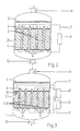
- a degassing and dewatering device in which the oil-like or oil-containing liquid, preferably insulating oil, in the direction of the arrow from a storage tank (not shown) or, for example, a transformer via a shut-off valve 17 via a -a arranged in a line Gear pump 14 is passed. From there, the insulating oil passes through the line -a- via a filter 15, a check valve 17 into the degassing boiler 1.
- the oil-like or oil-containing liquid preferably insulating oil
- the degassing boiler 1 is evacuated by a vacuum pump 18 via the vacuum line -c- that flows through the middle of the boiler lid through an inlet opening 11
- Insulating oil is distributed in a known manner via a distributor system 3 or a spray nozzle (not shown) and falls or flows down via guide elements 4 into a heating and / or degassing column 5, 6, which consists, for example, of three partially packed columns arranged horizontally one above the other (see 4) and is preferably formed from so-called Raschingrings, over which the insulating oil trickles.
- the packs 6 of the heating and / or degassing column 5,6 consisting of filled or filled up electrically conductive packing elements (16 or 16 'in FIG. 3 or FIG. 5) are connected in series and via connections
- the insulating oil 7 switchable to a power source 8 and electrically heated.
- the insulating oil In the upper part of the heating and / or degassing column 5, 6, the insulating oil is only slightly warmed, so that optimal degassing can take place; In the lower part, the insulating oil is raised to a predetermined temperature, which ensures optimal drainage of the oil.
- a vacuum pump 18 By means of a vacuum pump 18, the insulating oil escaping air and water vapor.
- a feed pump 19 for example a centrifugal pump, conveys the insulating oil through the line -b- from the degassing boiler 1 via a further shut-off valve 17 to a storage tank (not shown) or back into the transformer.
- the degassing room 2 is controlled by means of a level monitor 10.
- FIGS. 2, 3, 4 and 5 of the heating and / or degassing columns 5, 6; 5 ', 6' can be arranged such that they are flowed through both vertically in their longitudinal direction (Fig. 2 and Fig. 3), as well as the heating and / or degassing columns as shown in Figs. 4 and 5 5,6 are arranged horizontally and the insulating oil is fed through the inlet opening 11 via the distribution system 3 and guide elements 4 to the heating and / or degassing columns 5, 6 and likewise flows through the same in the vertical direction.
- the heating and / or degassing column according to FIG. 4 consists of partially packed columns arranged horizontally one above the other, which are electrically connected in series.
- the horizontally arranged heating and / or degassing column 5, 6, designed as a packed column, is suitable for devices with lower outputs.
- the Füil beneficiakladen can be filled in a known manner as regular packs 6,6 'in a housing 5,5', 5 ⁇ with packing 16 or as irregular packing 6,6 'in the housing 5,5', 5 ⁇ with packing 16 'loosely be.
- the individual fillers 16 and 16 '(indicated in Fig.3 and Fig.5 each) can also be welded together.
- the heating and / or degassing columns 5, 6 fastened to the inner wall of the boiler by means of brackets 21 are electrically connected in series via connections 7 and are designed to be electrically switchable and electrically heatable to a power source 8.
- the electric heater is preferably a resistance, a high-frequency or a microwave heater.
- the heating and / or degassing columns 5, 6 can also be in two or more column groups 5, 6; 5 ', 6' to be divided, which are electrically switchable and electrically heated to the corresponding current sources 8, 8 'via the connections 7, 7'.
- the heating and / or degassing columns 5, 6; 5 ', 6' have a geometric shape and are preferably cylindrical or prismatic, wire housings can also be provided.
- the housing surfaces of the heating and / or degassing columns 5, 6; 5 ', 6' can be perforated for better degassing and drainage.
Landscapes
- Chemical & Material Sciences (AREA)
- Chemical Kinetics & Catalysis (AREA)
- Degasification And Air Bubble Elimination (AREA)
- Vaporization, Distillation, Condensation, Sublimation, And Cold Traps (AREA)
Applications Claiming Priority (2)
| Application Number | Priority Date | Filing Date | Title |
|---|---|---|---|
| CH3078/89 | 1989-08-24 | ||
| CH307889A CH680050A5 (fr) | 1989-08-24 | 1989-08-24 |
Publications (3)
| Publication Number | Publication Date |
|---|---|
| EP0414126A2 true EP0414126A2 (fr) | 1991-02-27 |
| EP0414126A3 EP0414126A3 (en) | 1991-05-02 |
| EP0414126B1 EP0414126B1 (fr) | 1994-01-05 |
Family
ID=4248138
Family Applications (1)
| Application Number | Title | Priority Date | Filing Date |
|---|---|---|---|
| EP19900115684 Expired - Lifetime EP0414126B1 (fr) | 1989-08-24 | 1990-08-16 | Dispositif de dégazage |
Country Status (3)
| Country | Link |
|---|---|
| EP (1) | EP0414126B1 (fr) |
| CH (1) | CH680050A5 (fr) |
| DE (2) | DE4009333A1 (fr) |
Cited By (1)
| Publication number | Priority date | Publication date | Assignee | Title |
|---|---|---|---|---|
| EP1426844A1 (fr) | 2002-12-05 | 2004-06-09 | Micafil Ag | Dispositif pour réguler l'arrivée d'un fluide déversé dans un récipient et installation munie d'un tel dispositif |
Family Cites Families (13)
| Publication number | Priority date | Publication date | Assignee | Title |
|---|---|---|---|---|
| GB191015263A (en) * | 1910-06-25 | 1911-03-16 | Thomas Mcclelland | An Improved Method of and Apparatus for Evaporating, Volatilizing or Distilling Liquids and Solids. |
| DE882983C (de) * | 1951-05-05 | 1953-07-13 | Leybold S Nachfolger E | Verfahren und Einrichtung zum Entgasen und Destillieren von Fluessigkeiten im Vakuum mittels Fuellkoerpern |
| NL106854C (fr) * | 1957-04-29 | |||
| DE1302684B (fr) * | 1961-06-21 | 1971-04-01 | Automatic Process Control Inc | |
| DE1283806B (de) * | 1964-09-01 | 1968-11-28 | Siemens Ag | Vorrichtung zum Entgasen von Vergussmassen |
| SE333355B (fr) * | 1967-08-15 | 1971-03-15 | Sunds Ab | |
| DE2020871B2 (de) * | 1970-04-29 | 1975-09-25 | Leybold-Heraeus Gmbh & Co Kg, 5000 Koeln | Verfahren und Vorrichtung zur Vakuumentgasung von Flüssigkeiten |
| GB1417028A (en) * | 1972-11-22 | 1975-12-10 | Boc International Ltd | Liquid treatment apparatus |
| DE2262673C3 (de) * | 1972-12-21 | 1981-04-02 | Schladitz, Hermann J., Prof., 8000 München | Verfahren und Vorrichtung zum Verdampfen von Heizöl |
| CH547111A (de) * | 1973-02-22 | 1974-03-29 | Micafil Ag | Vorrichtung zum entgasen von fluessigkeiten. |
| NL7407357A (nl) * | 1974-06-21 | 1975-12-02 | Hick Hargreaves & Co Ltd | Inrichting voor het ontluchten van vloiestoffen. |
| JPS5772203A (en) * | 1980-10-24 | 1982-05-06 | Nippon Petrochemicals Co Ltd | Method of degassing electrically insulating oil |
| DE3414770A1 (de) * | 1984-04-18 | 1985-11-07 | Ebner & Co Kg Anlagen Und Apparate, 6419 Eiterfeld | Verfahren und vorrichtung zum entgasen von fluessigkeiten und deren verwendung |
-
1989
- 1989-08-24 CH CH307889A patent/CH680050A5/de not_active IP Right Cessation
-
1990
- 1990-03-23 DE DE19904009333 patent/DE4009333A1/de not_active Withdrawn
- 1990-08-16 DE DE90115684T patent/DE59004105D1/de not_active Expired - Fee Related
- 1990-08-16 EP EP19900115684 patent/EP0414126B1/fr not_active Expired - Lifetime
Cited By (1)
| Publication number | Priority date | Publication date | Assignee | Title |
|---|---|---|---|---|
| EP1426844A1 (fr) | 2002-12-05 | 2004-06-09 | Micafil Ag | Dispositif pour réguler l'arrivée d'un fluide déversé dans un récipient et installation munie d'un tel dispositif |
Also Published As
| Publication number | Publication date |
|---|---|
| EP0414126B1 (fr) | 1994-01-05 |
| DE4009333A1 (de) | 1991-02-28 |
| CH680050A5 (fr) | 1992-06-15 |
| EP0414126A3 (en) | 1991-05-02 |
| DE59004105D1 (de) | 1994-02-17 |
Similar Documents
| Publication | Publication Date | Title |
|---|---|---|
| EP3359288B1 (fr) | Dispositif réacteur destiné à la déshydrogénation d'un milieu vecteur | |
| DE3818844C1 (fr) | ||
| DE2207166C3 (de) | Kühlaggregat für Reaktionsapparate zur Durchführung exothermer chemischer Reaktionen | |
| DE1761106C3 (de) | Filter zur Reinigung von mit Feststoffen vermischten Flüssigkeiten | |
| WO1988005335A2 (fr) | Appareil de filtration pour filtrer des liquides contamines | |
| DE69411127T2 (de) | Wiederaufladbarer Dampferzeuger | |
| DE1275507B (de) | Duennschichtverdampfer | |
| DE2635862B2 (de) | Druckbehälter zum kontinuierlichen Abtrennen des Schwefels aus einer wäßrigen Schwefelsuspension | |
| DE3132530C2 (fr) | ||
| DE2256371A1 (de) | Vorrichtung an einem mediumtank | |
| EP0414126A2 (fr) | Dispositif de dégazage | |
| DE2354596B2 (de) | Elektrostatische Trennvorrichtung | |
| DE2710103A1 (de) | Fraktionierungsdestillationskolonne | |
| DE2358068A1 (de) | Vorrichtung zum erhitzen und entgasen von fluessigkeiten unter vakuum | |
| DE1542385B2 (de) | Verteiler für ein Emulsions-Behandlungsgerät | |
| DE1470610B2 (de) | Vorrichtung zum trennen von dispersionen im gleichbleibenden elektrischen feld | |
| DE3524083A1 (de) | Schmelzbehaelter | |
| CH659881A5 (de) | Vorrichtung zur verteilung der absorptionsfluessigkeit in einem absorptionskuehlapparat. | |
| EP0144360B1 (fr) | Filtres a cartouche et installation de filtrage | |
| EP0339706B1 (fr) | Dispositif pour la désodorisation de liquides organiques | |
| DE2442197C3 (fr) | ||
| EP0083429A1 (fr) | Friteuse | |
| DE1660629A1 (de) | Einrichtung zum Aufheizen von Kunststoffaeden | |
| DE1902309B2 (de) | Verteilerkopf zum Verteilen eines verflüssigten Gases in gleiche Teile | |
| DE3240631C2 (fr) |
Legal Events
| Date | Code | Title | Description |
|---|---|---|---|
| PUAI | Public reference made under article 153(3) epc to a published international application that has entered the european phase |
Free format text: ORIGINAL CODE: 0009012 |
|
| AK | Designated contracting states |
Kind code of ref document: A2 Designated state(s): CH DE FR GB IT LI |
|
| PUAL | Search report despatched |
Free format text: ORIGINAL CODE: 0009013 |
|
| AK | Designated contracting states |
Kind code of ref document: A3 Designated state(s): CH DE FR GB IT LI |
|
| 17P | Request for examination filed |
Effective date: 19910920 |
|
| 17Q | First examination report despatched |
Effective date: 19920812 |
|
| GRAA | (expected) grant |
Free format text: ORIGINAL CODE: 0009210 |
|
| AK | Designated contracting states |
Kind code of ref document: B1 Designated state(s): CH DE FR GB IT LI |
|
| REF | Corresponds to: |
Ref document number: 59004105 Country of ref document: DE Date of ref document: 19940217 |
|
| ITF | It: translation for a ep patent filed | ||
| GBT | Gb: translation of ep patent filed (gb section 77(6)(a)/1977) |
Effective date: 19940311 |
|
| ET | Fr: translation filed | ||
| PG25 | Lapsed in a contracting state [announced via postgrant information from national office to epo] |
Ref country code: GB Effective date: 19940816 |
|
| PLBE | No opposition filed within time limit |
Free format text: ORIGINAL CODE: 0009261 |
|
| STAA | Information on the status of an ep patent application or granted ep patent |
Free format text: STATUS: NO OPPOSITION FILED WITHIN TIME LIMIT |
|
| 26N | No opposition filed | ||
| GBPC | Gb: european patent ceased through non-payment of renewal fee |
Effective date: 19940816 |
|
| PG25 | Lapsed in a contracting state [announced via postgrant information from national office to epo] |
Ref country code: FR Effective date: 19950428 |
|
| REG | Reference to a national code |
Ref country code: CH Ref legal event code: PUE Owner name: MICAFIL VAKUUMTECHNIK AG |
|
| REG | Reference to a national code |
Ref country code: FR Ref legal event code: ST |
|
| REG | Reference to a national code |
Ref country code: CH Ref legal event code: NV Representative=s name: ASEA BROWN BOVERI AG ABT. TEI-IMMATERIALGUETERRECH |
|
| REG | Reference to a national code |
Ref country code: CH Ref legal event code: PUE Owner name: MICAFIL VAKUUMTECHNIK AG TRANSFER- MICAFIL AG Ref country code: CH Ref legal event code: NV Representative=s name: ABB SCHWEIZ AG INTELLECTUAL PROPERTY (CH-LC/IP) |
|
| PGFP | Annual fee paid to national office [announced via postgrant information from national office to epo] |
Ref country code: CH Payment date: 20020717 Year of fee payment: 13 |
|
| PGFP | Annual fee paid to national office [announced via postgrant information from national office to epo] |
Ref country code: DE Payment date: 20020809 Year of fee payment: 13 |
|
| PG25 | Lapsed in a contracting state [announced via postgrant information from national office to epo] |
Ref country code: LI Free format text: LAPSE BECAUSE OF NON-PAYMENT OF DUE FEES Effective date: 20030831 Ref country code: CH Free format text: LAPSE BECAUSE OF NON-PAYMENT OF DUE FEES Effective date: 20030831 |
|
| PG25 | Lapsed in a contracting state [announced via postgrant information from national office to epo] |
Ref country code: DE Free format text: LAPSE BECAUSE OF NON-PAYMENT OF DUE FEES Effective date: 20040302 |
|
| REG | Reference to a national code |
Ref country code: CH Ref legal event code: PL |
|
| PG25 | Lapsed in a contracting state [announced via postgrant information from national office to epo] |
Ref country code: IT Free format text: LAPSE BECAUSE OF NON-PAYMENT OF DUE FEES;WARNING: LAPSES OF ITALIAN PATENTS WITH EFFECTIVE DATE BEFORE 2007 MAY HAVE OCCURRED AT ANY TIME BEFORE 2007. THE CORRECT EFFECTIVE DATE MAY BE DIFFERENT FROM THE ONE RECORDED. Effective date: 20050816 |