EP0414242A1 - Rohranschluss und Rohr mit einem Rohranschluss - Google Patents
Rohranschluss und Rohr mit einem Rohranschluss Download PDFInfo
- Publication number
- EP0414242A1 EP0414242A1 EP19900116164 EP90116164A EP0414242A1 EP 0414242 A1 EP0414242 A1 EP 0414242A1 EP 19900116164 EP19900116164 EP 19900116164 EP 90116164 A EP90116164 A EP 90116164A EP 0414242 A1 EP0414242 A1 EP 0414242A1
- Authority
- EP
- European Patent Office
- Prior art keywords
- joint
- male
- female
- pipe
- joints
- Prior art date
- Legal status (The legal status is an assumption and is not a legal conclusion. Google has not performed a legal analysis and makes no representation as to the accuracy of the status listed.)
- Granted
Links
Images


Classifications
-
- F—MECHANICAL ENGINEERING; LIGHTING; HEATING; WEAPONS; BLASTING
- F16—ENGINEERING ELEMENTS AND UNITS; GENERAL MEASURES FOR PRODUCING AND MAINTAINING EFFECTIVE FUNCTIONING OF MACHINES OR INSTALLATIONS; THERMAL INSULATION IN GENERAL
- F16L—PIPES; JOINTS OR FITTINGS FOR PIPES; SUPPORTS FOR PIPES, CABLES OR PROTECTIVE TUBING; MEANS FOR THERMAL INSULATION IN GENERAL
- F16L15/00—Screw-threaded joints; Forms of screw-threads for such joints
- F16L15/001—Screw-threaded joints; Forms of screw-threads for such joints with conical threads
- F16L15/004—Screw-threaded joints; Forms of screw-threads for such joints with conical threads with axial sealings having at least one plastically deformable sealing surface
-
- F—MECHANICAL ENGINEERING; LIGHTING; HEATING; WEAPONS; BLASTING
- F16—ENGINEERING ELEMENTS AND UNITS; GENERAL MEASURES FOR PRODUCING AND MAINTAINING EFFECTIVE FUNCTIONING OF MACHINES OR INSTALLATIONS; THERMAL INSULATION IN GENERAL
- F16L—PIPES; JOINTS OR FITTINGS FOR PIPES; SUPPORTS FOR PIPES, CABLES OR PROTECTIVE TUBING; MEANS FOR THERMAL INSULATION IN GENERAL
- F16L15/00—Screw-threaded joints; Forms of screw-threads for such joints
- F16L15/001—Screw-threaded joints; Forms of screw-threads for such joints with conical threads
- F16L15/003—Screw-threaded joints; Forms of screw-threads for such joints with conical threads with sealing rings
-
- F—MECHANICAL ENGINEERING; LIGHTING; HEATING; WEAPONS; BLASTING
- F16—ENGINEERING ELEMENTS AND UNITS; GENERAL MEASURES FOR PRODUCING AND MAINTAINING EFFECTIVE FUNCTIONING OF MACHINES OR INSTALLATIONS; THERMAL INSULATION IN GENERAL
- F16L—PIPES; JOINTS OR FITTINGS FOR PIPES; SUPPORTS FOR PIPES, CABLES OR PROTECTIVE TUBING; MEANS FOR THERMAL INSULATION IN GENERAL
- F16L15/00—Screw-threaded joints; Forms of screw-threads for such joints
- F16L15/006—Screw-threaded joints; Forms of screw-threads for such joints with straight threads
- F16L15/008—Screw-threaded joints; Forms of screw-threads for such joints with straight threads with sealing rings
-
- F—MECHANICAL ENGINEERING; LIGHTING; HEATING; WEAPONS; BLASTING
- F16—ENGINEERING ELEMENTS AND UNITS; GENERAL MEASURES FOR PRODUCING AND MAINTAINING EFFECTIVE FUNCTIONING OF MACHINES OR INSTALLATIONS; THERMAL INSULATION IN GENERAL
- F16L—PIPES; JOINTS OR FITTINGS FOR PIPES; SUPPORTS FOR PIPES, CABLES OR PROTECTIVE TUBING; MEANS FOR THERMAL INSULATION IN GENERAL
- F16L17/00—Joints with packing adapted to sealing by fluid pressure
- F16L17/06—Joints with packing adapted to sealing by fluid pressure with sealing rings arranged between the end surfaces of the pipes or flanges or arranged in recesses in the pipe ends or flanges
- F16L17/067—Plastics sealing rings
Definitions
- This invention relates to the field of pipe joint and pipe with pipe joint which are being used in oil field technology or other general purpose areas, wherein a high sealing capability is required to prevent fluid in the piping system from leaking.
- joints for metallic pipe, plastic pipe, and fiber reinforced plastic pipe bell and spigot type joint, or glued joint, flanged type joint, screwed type joint, etc are utilized.
- the glued joint is mainly used for plastic pipes.
- the inside of the end of a plastic pipe is tapered which constitutes a female joint, whereas the outside of the end of another plastic pipe is tapered which constitutes a male joint. Both joints are jointed together by adhesive painted on the tapered surfaces. In some cases the tapered surfaces are equipped with screw and painted with adhesive.
- the flanged type joint is widely used in the metallic, plastic, and fiber reinforced plastic pipes.
- the hydraulic pressure of the fluid which is within the range of the sealing capacity, is comparatively low; 10 to 35 kgf/cm2 for plastic pipe, and about 210 kgf/cm2 for metallic pipe.
- the screwed type joint is widely used one.
- the screw may be a pair of parallel screws or tapered screws.
- the sealing is done by an O ring or by using the contact pressure between the thread of the screw in case of the metallic pipe joint.
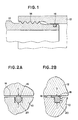
- Figure 1 shows the sectional view of the conventional screwed pipe joint.
- FIGS. 1 and 2B show the enlarged views of Figure 1 with respect to the parts surrouding the O ring.
- a predetermined force "a" is applied on the O ring.
- Figure 2B when hydraulic pressure is applied on the O ring, the ring is deformed and a part of the O ring is pressed in the gap of the joints 18 out of the groove 20.
- the force applied on the ring reaches "b" as the combined effect of "a” plus hydraulic pressure, the ring is destroyed and the fluid leaks into the gap 18.
- the problem of leakage is inevitable, with the exception of the joints with the materials, metal with metal.
- a pipe joint having male and female joints comprising: a coupling means which couples said male joint with the female joint, a contact surface on the male joint, a contact surface on the female surface, which is cotacted with the contact surface of the male joint in coupling the male joint with the female joint, a groove situated adjacent to said contact surface of which opening faces with the surface of an opposite joint, and connected to fluid in pipe via a clearance between the joints provided next to the groove, and an O ring which is contained in said groove, of which ends are contacted with the male and female joints.
- the gap between the male and the female joints should be nullified.
- the inventors solved the problem by contacting a part of the both joint adjacent to O ring, which is situated at the opposite side of the pressurized zone. By providing the contact zone, the deformation of the O ring is confined in the groove without the destruction of the ring.
- the means of coupling the male and female joints may be screws or flanges.
- the materials of the male and female joints may be metallic, plastic, or of fiber reinforced plastic.
- the groove may be attached to the male or the female joint.
- the gap between the male and the female joints denoted as the gap 18 in Figure 2B, should be nullified.
- the inventors solved the problem by contacting parts of the both joints adjacent to O ring, which are situated at the opposite side of the pressurized zone. By providing the contact zone, the deformation of the O ring is confined in the groove 20 denoted in Figure 2B without the destruction of the O ring.
- Figure 3 is the sectional view of the screw joint of a typical embodiment of the invention.
- the male joint 22 is coupled with the female joint 24 by the screw 26.
- the both joints are contacted at the contact surface 28.
- the unthreaded zone 29 is provided between the screw and the contact surface. Adjacent to the contact surface on the side of the male joint 22, the groove 30 for accomodating the O ring 32 is provided.
- the gap 31 between the both joint is provided to fit the male joint 22 into the female joint 24.
- Figures 4A and 4B are the enlarged views of Figure 3 with respect to the parts surrouding the O ring.
- a predetermined force "a" is applied on the O ring.
- Figure 4B when hydraulic pressure is applied on the ring, the ring is deformed.
- the force applied on the ring reaches "c" as the combined effect of "a” plus hydraulic pressure, the ring is deformed and pressed to the wall of the groove.
- the angle made by the contact zone 28 and the axial direction of the joints is denoted as ⁇ . The angle may vary between 0 to 90 degree.
- the angle is pertinent between 20 to 80 degree to ensure the good contact.
- the O ring and the groove are provided on the side of the male joint.
- the effect is the same when the O ring and the groove are provided on the female side.
- Figure 5 is an example of the embodiment of the invention.
- the male joint 33 is coupled with the female joint 34 by the thread 36.
- the both joints are contacted at the contact surface 38.
- the unthreaded zone 40 is provided between the screw and the contact surface.
- the groove 42 for accomodating the O ring 44 is provided Adjacent to the groove 42 the gap 46 between the both joint is provided to ensure the good contact.
- the O ring and the groove are provided on the side of the male joint. However the effect is the same when the O ring and the groove are provided on the female side.
- Figure 6 is another example of the embodiment of the invention.
- the male joint 50 is coupled with the female joint 52 by the tapered thread 54.
- the both joints are contacted at the contact surface 56.
- the unthreaded zone 58 is provided between the screw and the contact surface.
- the groove 60 for accomodating the O ring 62 is provided Adjacent to the groove 60 the gap 61 between the both joints is provided to ensure the good contact.
- the shape of the section of the groove 60 is triangular.
- the O ring and the groove are provided on the side of the female joint.
- the effect is the same when the O ring and the groove are provided on the male side.
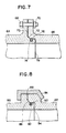
- Figure 7 is another example of the embodiment of the invention.
- the flanged male joint 64 is coupled with the flanged female joint 66 by the bolt 68 and the nut 70 The both joints are contacted at the contact surface 72.
- the clearance 73 is provided between the joints. Adjacent to the contact zone on the side of the flanged male joint 64, the groove 74 for accomodating the O ring 76 is provided. Adjacent to the groove 74 the gap 78 in between the both joint is provided to ensure the good contact. In this case the shape of the section of the groove 74 is square.
- the O ring and the groove are provided on the side of the male joint.
- the effect is the same when the O ring and the groove are provided on the female side.
- Figure 8 is another example of the embodiment of the invention.
- the flanged male joint 80 is coupled with the flanged female joint 82 by the means of engaging the flanges, in this case, by shrinkage fitting fixture 84.
- the both joints are contacted at the contact surface 86.
- the clearance 88 is provided between the joints. Adjacent to the contact zone on the side of the flanged male joint 80, the groove 90 for accomodating the O ring 92 is provided. Adjacent to the groove 90 the gap 94 between the both joint is provided to ensure the good contact.
- the shaped of the groove 90 is square sectional shape.
- the O ring and the groove are provided on the side of the male joint.
- the effect is the same when the O ring and the groove are provided on the female side.
- the hydrulic pressure tests are carried out to guarantee the invention.
- the test is conducted by the method described in ASTM D-1599 " THE SHORT TIME HYDRAULIC FAILURE PRESSURE OF PLASTIC PIPE, TUBING, AND FITTING " .
- the invented joints are used in tests from 1 to 5, and conventional joints are used in tests 6 and 7.
- the test sample is made of FRP male screwed joint and 13 Cr steel female screwed joint.
- the FRP tube has the dimensions; 50 mm in internal diameter and 8 mm in thickness.
- the test was interrupted since the FRP tubing was destructed at the pressure of 840 kgf/cm2.
- the test sample is made of FRP male and female screwed joints.
- the FRP tube has the dimensions; 50 mm in internal diameter and 8 mm in thickness.
- the test sample is made of metallic male screwed joint and FRP female screwed joint.
- the FRP tube has the dimensions; 50 mm in internal diameter and 12 mm in thickness.
- the test pressure without the destruction of the joints was more than 1050kgf/cm2, which is the target value.
- the test sample is made of metallic male flanged joint and FRP female flanged joint.
- the FRP tube has the dimensions; 50 mm in internal diameter and 12 mm in thickness.
- the test pressure without the destruction of the joints was more than 1000 kgf/cm2, which is the target value.
- the test sample is made of polyethyrene male screwed joint and polyethyrene female screwed joint.
- the polyethyrene tube has the dimensions; 48 mm in internal diameter and 6 mm in thickness.
- the test was interrupted since the polyethyrene tubing was destructed at the pressure of 40 kgf/cm2.
- test sample is made of FRP male screwed joint and 13 Cr steel female screwed joint.
- the test was interrupted since the leakage was found at the joint at the pressure of 450 kgf/cm2.
- test sample is made of FRP screwed joint.
- the test was interrupted since the leakage was found at the joint at the pressure of 480 kgf/cm2.
Landscapes
- Engineering & Computer Science (AREA)
- General Engineering & Computer Science (AREA)
- Mechanical Engineering (AREA)
- Physics & Mathematics (AREA)
- Fluid Mechanics (AREA)
- Flanged Joints, Insulating Joints, And Other Joints (AREA)
- Quick-Acting Or Multi-Walled Pipe Joints (AREA)
- Non-Disconnectible Joints And Screw-Threaded Joints (AREA)
Applications Claiming Priority (2)
| Application Number | Priority Date | Filing Date | Title |
|---|---|---|---|
| JP97920/89U | 1989-08-24 | ||
| JP9792089 | 1989-08-24 |
Publications (2)
| Publication Number | Publication Date |
|---|---|
| EP0414242A1 true EP0414242A1 (de) | 1991-02-27 |
| EP0414242B1 EP0414242B1 (de) | 1992-07-15 |
Family
ID=14205133
Family Applications (1)
| Application Number | Title | Priority Date | Filing Date |
|---|---|---|---|
| EP90116164A Expired - Lifetime EP0414242B1 (de) | 1989-08-24 | 1990-08-23 | Rohranschluss und Rohr mit einem Rohranschluss |
Country Status (3)
| Country | Link |
|---|---|
| EP (1) | EP0414242B1 (de) |
| CA (1) | CA2023087A1 (de) |
| DE (1) | DE69000198T2 (de) |
Cited By (4)
| Publication number | Priority date | Publication date | Assignee | Title |
|---|---|---|---|---|
| EP0565957A1 (de) * | 1992-04-11 | 1993-10-20 | Friatec Ag Keramik- Und Kunststoffwerke | Übergangsverbinder für eine Rohrleitung |
| EP1659329A1 (de) * | 2004-11-23 | 2006-05-24 | Fenis Teknik Ürünler A.S. | Verfahren und Vorrichtung für Korrosionsvermeidung der Verbindungsenden einer Heizanlage, insbesondere für Aluminiumflachheizkörper |
| DE202008014447U1 (de) * | 2008-10-30 | 2010-03-18 | Rehau Ag + Co | Verbindungsanordnung |
| WO2012081019A3 (en) * | 2010-12-14 | 2012-10-26 | Amiad Water Systems Ltd. | Filtration system and assembly thereof |
Families Citing this family (1)
| Publication number | Priority date | Publication date | Assignee | Title |
|---|---|---|---|---|
| CN104455811A (zh) * | 2014-12-07 | 2015-03-25 | 无锡高卓流体设备有限公司 | 一种新型管接头 |
Citations (3)
| Publication number | Priority date | Publication date | Assignee | Title |
|---|---|---|---|---|
| GB1503395A (en) * | 1975-09-19 | 1978-03-08 | Attock Oilfield Equip | Pipe connector |
| US4822081A (en) * | 1987-03-23 | 1989-04-18 | Xl Systems | Driveable threaded tubular connection |
| US4893844A (en) * | 1983-04-29 | 1990-01-16 | Baker Hughes Incorporated | Tubular coupling with ventable seal |
-
1990
- 1990-08-10 CA CA002023087A patent/CA2023087A1/en not_active Abandoned
- 1990-08-23 DE DE9090116164T patent/DE69000198T2/de not_active Expired - Fee Related
- 1990-08-23 EP EP90116164A patent/EP0414242B1/de not_active Expired - Lifetime
Patent Citations (3)
| Publication number | Priority date | Publication date | Assignee | Title |
|---|---|---|---|---|
| GB1503395A (en) * | 1975-09-19 | 1978-03-08 | Attock Oilfield Equip | Pipe connector |
| US4893844A (en) * | 1983-04-29 | 1990-01-16 | Baker Hughes Incorporated | Tubular coupling with ventable seal |
| US4822081A (en) * | 1987-03-23 | 1989-04-18 | Xl Systems | Driveable threaded tubular connection |
Cited By (4)
| Publication number | Priority date | Publication date | Assignee | Title |
|---|---|---|---|---|
| EP0565957A1 (de) * | 1992-04-11 | 1993-10-20 | Friatec Ag Keramik- Und Kunststoffwerke | Übergangsverbinder für eine Rohrleitung |
| EP1659329A1 (de) * | 2004-11-23 | 2006-05-24 | Fenis Teknik Ürünler A.S. | Verfahren und Vorrichtung für Korrosionsvermeidung der Verbindungsenden einer Heizanlage, insbesondere für Aluminiumflachheizkörper |
| DE202008014447U1 (de) * | 2008-10-30 | 2010-03-18 | Rehau Ag + Co | Verbindungsanordnung |
| WO2012081019A3 (en) * | 2010-12-14 | 2012-10-26 | Amiad Water Systems Ltd. | Filtration system and assembly thereof |
Also Published As
| Publication number | Publication date |
|---|---|
| CA2023087A1 (en) | 1991-02-25 |
| DE69000198T2 (de) | 1993-03-04 |
| DE69000198D1 (de) | 1992-08-20 |
| EP0414242B1 (de) | 1992-07-15 |
Similar Documents
| Publication | Publication Date | Title |
|---|---|---|
| CA1301800C (en) | High pressure coupling | |
| RU2452888C2 (ru) | Резьбовое соединение с уплотнением, выдерживающим повышенное давление | |
| RU2058505C1 (ru) | Герметичное соединение металлических труб | |
| US5906402A (en) | Dual synchronized thread fluid connector cross-reference to related application | |
| US5069485A (en) | Brittle lined pipe connector | |
| AU2014366892B2 (en) | Dismantling joint | |
| ZA200105197B (en) | Pipe coupling. | |
| US5131695A (en) | Coupling with teflon seat | |
| US3468566A (en) | Conduit coupling | |
| CA1110292A (en) | Flange sealing joint with removable metal gasket | |
| US4940259A (en) | Swivel lug pipe joint connections | |
| EP0414242B1 (de) | Rohranschluss und Rohr mit einem Rohranschluss | |
| US5161835A (en) | Pipe joint mechanism having high maintainability with wrap-around seal member | |
| CN2264832Y (zh) | 多功能管道接头 | |
| JP2026042909A (ja) | 油井管連結構造 | |
| GB2115897A (en) | Pipe couplings | |
| EP0371063A1 (de) | Feuerwiderstandsfähige rohrkupplungen. | |
| US3356391A (en) | Pipe or tube coupling device | |
| US5649797A (en) | Nut and bolt securing device | |
| US5240293A (en) | Brittle lined pipe connector | |
| JPH03234996A (ja) | パイプの継手構造 | |
| US3108827A (en) | Plastic fitting for substantially non-deformable tubes | |
| RU2014542C1 (ru) | Штуцерно-торцевое соединение трубопроводов | |
| RU2094688C1 (ru) | Соединение трубопроводов | |
| CA1313402C (en) | Pressure energized sealing joint |
Legal Events
| Date | Code | Title | Description |
|---|---|---|---|
| PUAI | Public reference made under article 153(3) epc to a published international application that has entered the european phase |
Free format text: ORIGINAL CODE: 0009012 |
|
| 17P | Request for examination filed |
Effective date: 19900823 |
|
| AK | Designated contracting states |
Kind code of ref document: A1 Designated state(s): DE FR GB |
|
| 17Q | First examination report despatched |
Effective date: 19911112 |
|
| GRAA | (expected) grant |
Free format text: ORIGINAL CODE: 0009210 |
|
| AK | Designated contracting states |
Kind code of ref document: B1 Designated state(s): DE FR GB |
|
| RIN1 | Information on inventor provided before grant (corrected) |
Inventor name: ISHIHARA, TOSHIO, C/O PATENT & LICENCE DEPT. Inventor name: NAKANO, TAKASHI, C/O PATENT & LICENCE DEPT. Inventor name: AKIYAMA, HIROSHI, C/O PATENT & LICENCE DEPT. |
|
| REF | Corresponds to: |
Ref document number: 69000198 Country of ref document: DE Date of ref document: 19920820 |
|
| PGFP | Annual fee paid to national office [announced via postgrant information from national office to epo] |
Ref country code: FR Payment date: 19920827 Year of fee payment: 3 |
|
| ET | Fr: translation filed | ||
| PLBE | No opposition filed within time limit |
Free format text: ORIGINAL CODE: 0009261 |
|
| STAA | Information on the status of an ep patent application or granted ep patent |
Free format text: STATUS: NO OPPOSITION FILED WITHIN TIME LIMIT |
|
| 26N | No opposition filed | ||
| PG25 | Lapsed in a contracting state [announced via postgrant information from national office to epo] |
Ref country code: FR Effective date: 19940429 |
|
| REG | Reference to a national code |
Ref country code: FR Ref legal event code: ST |
|
| PGFP | Annual fee paid to national office [announced via postgrant information from national office to epo] |
Ref country code: GB Payment date: 19950814 Year of fee payment: 6 |
|
| PGFP | Annual fee paid to national office [announced via postgrant information from national office to epo] |
Ref country code: DE Payment date: 19950828 Year of fee payment: 6 |
|
| PG25 | Lapsed in a contracting state [announced via postgrant information from national office to epo] |
Ref country code: GB Effective date: 19960823 |
|
| GBPC | Gb: european patent ceased through non-payment of renewal fee |
Effective date: 19960823 |
|
| PG25 | Lapsed in a contracting state [announced via postgrant information from national office to epo] |
Ref country code: DE Effective date: 19970501 |