EP0414312A1 - Unité de lampe/réflecteur - Google Patents
Unité de lampe/réflecteur Download PDFInfo
- Publication number
- EP0414312A1 EP0414312A1 EP90202225A EP90202225A EP0414312A1 EP 0414312 A1 EP0414312 A1 EP 0414312A1 EP 90202225 A EP90202225 A EP 90202225A EP 90202225 A EP90202225 A EP 90202225A EP 0414312 A1 EP0414312 A1 EP 0414312A1
- Authority
- EP
- European Patent Office
- Prior art keywords
- lamp
- reflector
- neck
- shaped portion
- seal
- Prior art date
- Legal status (The legal status is an assumption and is not a legal conclusion. Google has not performed a legal analysis and makes no representation as to the accuracy of the status listed.)
- Withdrawn
Links
- 239000004568 cement Substances 0.000 claims abstract description 13
- 239000002184 metal Substances 0.000 claims abstract description 9
- 229910052751 metal Inorganic materials 0.000 claims abstract description 9
- 239000004020 conductor Substances 0.000 claims description 4
- 239000004411 aluminium Substances 0.000 description 2
- 229910052782 aluminium Inorganic materials 0.000 description 2
- XAGFODPZIPBFFR-UHFFFAOYSA-N aluminium Chemical compound [Al] XAGFODPZIPBFFR-UHFFFAOYSA-N 0.000 description 2
- 150000001875 compounds Chemical class 0.000 description 2
- 239000011521 glass Substances 0.000 description 2
- 210000002105 tongue Anatomy 0.000 description 2
- 229910001369 Brass Inorganic materials 0.000 description 1
- 239000010951 brass Substances 0.000 description 1
- 238000010276 construction Methods 0.000 description 1
- 229910052736 halogen Inorganic materials 0.000 description 1
- 150000002367 halogens Chemical class 0.000 description 1
- 238000007373 indentation Methods 0.000 description 1
- 239000000463 material Substances 0.000 description 1
- 238000004080 punching Methods 0.000 description 1
Images
Classifications
-
- F—MECHANICAL ENGINEERING; LIGHTING; HEATING; WEAPONS; BLASTING
- F21—LIGHTING
- F21S—NON-PORTABLE LIGHTING DEVICES; SYSTEMS THEREOF; VEHICLE LIGHTING DEVICES SPECIALLY ADAPTED FOR VEHICLE EXTERIORS
- F21S8/00—Lighting devices intended for fixed installation
-
- F—MECHANICAL ENGINEERING; LIGHTING; HEATING; WEAPONS; BLASTING
- F21—LIGHTING
- F21V—FUNCTIONAL FEATURES OR DETAILS OF LIGHTING DEVICES OR SYSTEMS THEREOF; STRUCTURAL COMBINATIONS OF LIGHTING DEVICES WITH OTHER ARTICLES, NOT OTHERWISE PROVIDED FOR
- F21V19/00—Fastening of light sources or lamp holders
- F21V19/0005—Fastening of light sources or lamp holders of sources having contact pins, wires or blades, e.g. pinch sealed lamp
-
- H—ELECTRICITY
- H01—ELECTRIC ELEMENTS
- H01J—ELECTRIC DISCHARGE TUBES OR DISCHARGE LAMPS
- H01J5/00—Details relating to vessels or to leading-in conductors common to two or more basic types of discharge tubes or lamps
- H01J5/50—Means forming part of the tube or lamps for the purpose of providing electrical connection to it
- H01J5/54—Means forming part of the tube or lamps for the purpose of providing electrical connection to it supported by a separate part, e.g. base
- H01J5/58—Means for fastening the separate part to the vessel, e.g. by cement
Definitions
- the invention relates to a lamp/reflector unit comprising - a concave reflector with an axis, which has near its top a neck-shaped portion around that axis, - an electric lamp provided with - a lamp vessel having a seal, - an electric element in the lamp vessel, - current supply conductors extending from the electric element through the seal to the exterior, - a metal centring member in the neck-shaped portion having a transverse wall cross to the axis of the reflector, which wall has an opening in which the seal is accommodated, the lamp vessel being secured in the neck-shaped portion by means of cement.
- Such lamp/reflector units are commercially available.
- the centring member - a flat metal plate, a metal plate having a cylindrical rim, or a metal bush - facilitates assembly of the lamp in the reflector in a pre-determined position of the electric element relative to the reflector owing to the fact that the member centres the seal in the neck-shaped portion. By shifting and/or tilting the lamp vessel, it is possible to bring the electric element in the correct position.
- the centring member also has for its object to prevent the cement from flowing from the neck-shaped portion before it has set and from being deposited on the reflector.
- the invention has for its object to provide a lamp/reflector unit of the type described in the opening paragraph which amongst others is of a simple construction and in which fracture of the lamp vessel is avoided.
- This object is achieved in that recesses extend from the opening in the transverse wall of the centring member into that transverse wall.
- the invention is based on the recognition of the fact that the curing of the cement causes strain in the seal of the lamp vessel. At the surface of the cement mass remote from the reflector this compound has room to expand and thus to relieve strain. The part of the cement mass facing the reflector does not have this possibility in the known unit owing to the fact that the centring member is present there.
- the measure according to the invention gives the centring member flexibility in the axial direction of the reflector. The result is that strain in the cement mass, and thus in the seal, is reduced.
- the number and locations of the incisions depend on the nature and the thickness of the material of the centring member, the properties of the cement mass, and the temperature/time curve traversed during curing of the cement mass. It is easy for those skilled in the art, however, to determine the required configuration of the incisions for a given lamp by means of a few test samples.
- the electric element is an incandescent body, whether or not in a halogen-containing gas, or a pair of electrodes in an ionizable medium.
- the concave reflector is usually made of metal or glass.
- the centring member may be included in the neck-shaped portion with clamping fit, it may be secured in it by means of the cement compound holding the lamp vessel, or it may be fixed in it by means of indentations in the neck-shaped portion, or by means of welded or soldered joints.
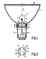
- the lamp/reflector unit has a concave reflector 1 with an axis 2, which has near its apex a neck-shaped portion 3 around that axis 2.
- the reflector 1 shown is of metal, for example aluminium
- An electric lamp 4 is provided with a lamp vessel 5 having a seal 6.
- An electric element 7, an incandescent body, is arranged in the lamp vessel.
- Current supply conductors 8 extend from the electric element 7 through the seal 6 to the exterior.
- a metal centring member 9 having a transverse wall 10 at right angles to the axis 2 of the reflector 1, which wall has an opening 11 (Fig. 2) in which the seal 6 is accommodated.
- the lamp vessel 5 is fixed in the neck-shaped portion 3 with cement 12.
- the centring member 9 has the shape of a bush, the base of which is the transverse wall 10. The centring member 9 is applied in the neck-shaped portion 3 with clamping fit.
- recesses 13 extend from the opening 11 in the transverse wall 10 of the centring member 9 (Fig. 2), substantially along the neck-shaped portion 3 (Fig. 1).
- the centring member 9 is made of brass with a thickness of 0,2 mm, while the reflector 1 is made of aluminium.
- the recesses 13 run as circular arcs in the transverse wall 10, thus forming flexible tongues 14 (Fig. 2) in that wall.
- Fig. 1 shows exaggeratedly that these tongues 14 are pressed outwards by the cement mass 12 from the original flat plane of the transverse wall 10.
- a lamp cap 15 is fixed around a neck-shaped portion 3, but alternatively the current supply conductors 8 may act as contact pins.
- the reflector 1 is closed off with a glass plate 16.
Landscapes
- Engineering & Computer Science (AREA)
- General Engineering & Computer Science (AREA)
- Non-Portable Lighting Devices Or Systems Thereof (AREA)
- Arrangement Of Elements, Cooling, Sealing, Or The Like Of Lighting Devices (AREA)
Applications Claiming Priority (2)
| Application Number | Priority Date | Filing Date | Title |
|---|---|---|---|
| NL8902102 | 1989-08-21 | ||
| NL8902102 | 1989-08-21 |
Publications (1)
| Publication Number | Publication Date |
|---|---|
| EP0414312A1 true EP0414312A1 (fr) | 1991-02-27 |
Family
ID=19855187
Family Applications (1)
| Application Number | Title | Priority Date | Filing Date |
|---|---|---|---|
| EP90202225A Withdrawn EP0414312A1 (fr) | 1989-08-21 | 1990-08-20 | Unité de lampe/réflecteur |
Country Status (4)
| Country | Link |
|---|---|
| US (1) | US5053935A (fr) |
| EP (1) | EP0414312A1 (fr) |
| JP (1) | JPH0395853A (fr) |
| HU (1) | HU203613B (fr) |
Cited By (4)
| Publication number | Priority date | Publication date | Assignee | Title |
|---|---|---|---|---|
| WO1996027205A1 (fr) * | 1995-03-02 | 1996-09-06 | Philips Electronics N.V. | Lampe electrique a reflecteur |
| EP1005061A1 (fr) * | 1998-11-26 | 2000-05-31 | Phoenix Electric Co., Ltd. | Lampe à halogène avec réflecteur |
| WO2004102613A3 (fr) * | 2003-05-16 | 2005-03-31 | Koninkl Philips Electronics Nv | Lampe et son procede de fabrication |
| WO2007110318A1 (fr) * | 2006-03-28 | 2007-10-04 | Osram Gesellschaft mit beschränkter Haftung | Procédé de fabrication d'un corps moulé isolé électriquement et douille pour une LAMPE |
Families Citing this family (7)
| Publication number | Priority date | Publication date | Assignee | Title |
|---|---|---|---|---|
| US5206799A (en) * | 1990-11-22 | 1993-04-27 | U.S. Philips Corporation | Lamp/reflector unit |
| USD352120S (en) | 1992-12-16 | 1994-11-01 | Gte Products Corporation | Reflector lamp with neck extender |
| USD352121S (en) | 1992-12-17 | 1994-11-01 | Gte Products Corporation | Reflector lamp with neck extender |
| DE4305503A1 (de) * | 1993-02-23 | 1994-08-25 | Patent Treuhand Ges Fuer Elektrische Gluehlampen Mbh | Einseitig gesockelte elektrische Lampe |
| EP1079740B1 (fr) * | 1998-05-21 | 2007-08-29 | Christopher J. Walshe | Systeme de fixation des tissus |
| TW570288U (en) * | 1998-11-18 | 2004-01-01 | Matsushita Electric Industrial Co Ltd | Lamp with reflector |
| US20030111944A1 (en) * | 2001-12-13 | 2003-06-19 | Vildana Jahic | Bulb attachment for temperature limited environment |
Citations (3)
| Publication number | Priority date | Publication date | Assignee | Title |
|---|---|---|---|---|
| US3026443A (en) * | 1959-11-30 | 1962-03-20 | Westinghouse Electric Corp | Electric lamp and base therefor |
| FR2385980A1 (fr) * | 1977-03-28 | 1978-10-27 | Patent Treuhand Ges Fuer Elektrische Gluehlampen Mbh | Module forme d'une lampe a incandescence a halogene et d'un reflecteur |
| EP0252447A2 (fr) * | 1986-07-07 | 1988-01-13 | GTE Products Corporation | Lampe électrique à porte-couverture flexible |
Family Cites Families (3)
| Publication number | Priority date | Publication date | Assignee | Title |
|---|---|---|---|---|
| US3314331A (en) * | 1965-04-29 | 1967-04-18 | Gen Electric | Photographic projection system and lamp |
| DE2933359A1 (de) * | 1979-08-17 | 1981-03-26 | Philips Patentverwaltung GmbH, 22335 Hamburg | Elektrische lampe mit einem huelsenfoermigen sockel |
| DE2938189C2 (de) * | 1979-09-21 | 1984-07-26 | Patent-Treuhand-Gesellschaft für elektrische Glühlampen mbH, 8000 München | Glühlampe mit am Quetschfuß kittlos befestigten Lampensockel |
-
1990
- 1990-08-15 US US07/567,855 patent/US5053935A/en not_active Expired - Fee Related
- 1990-08-17 HU HU905059A patent/HU203613B/hu unknown
- 1990-08-20 JP JP2217234A patent/JPH0395853A/ja active Pending
- 1990-08-20 EP EP90202225A patent/EP0414312A1/fr not_active Withdrawn
Patent Citations (3)
| Publication number | Priority date | Publication date | Assignee | Title |
|---|---|---|---|---|
| US3026443A (en) * | 1959-11-30 | 1962-03-20 | Westinghouse Electric Corp | Electric lamp and base therefor |
| FR2385980A1 (fr) * | 1977-03-28 | 1978-10-27 | Patent Treuhand Ges Fuer Elektrische Gluehlampen Mbh | Module forme d'une lampe a incandescence a halogene et d'un reflecteur |
| EP0252447A2 (fr) * | 1986-07-07 | 1988-01-13 | GTE Products Corporation | Lampe électrique à porte-couverture flexible |
Cited By (6)
| Publication number | Priority date | Publication date | Assignee | Title |
|---|---|---|---|---|
| WO1996027205A1 (fr) * | 1995-03-02 | 1996-09-06 | Philips Electronics N.V. | Lampe electrique a reflecteur |
| CN1096106C (zh) * | 1995-03-02 | 2002-12-11 | 皇家菲利浦电子有限公司 | 电反射灯 |
| EP1005061A1 (fr) * | 1998-11-26 | 2000-05-31 | Phoenix Electric Co., Ltd. | Lampe à halogène avec réflecteur |
| WO2004102613A3 (fr) * | 2003-05-16 | 2005-03-31 | Koninkl Philips Electronics Nv | Lampe et son procede de fabrication |
| US7372207B2 (en) | 2003-05-16 | 2008-05-13 | Koninklijke Philips Electronics, N.V. | Lamp and method of manufacturing a lamp |
| WO2007110318A1 (fr) * | 2006-03-28 | 2007-10-04 | Osram Gesellschaft mit beschränkter Haftung | Procédé de fabrication d'un corps moulé isolé électriquement et douille pour une LAMPE |
Also Published As
| Publication number | Publication date |
|---|---|
| HUT54829A (en) | 1991-03-28 |
| US5053935A (en) | 1991-10-01 |
| JPH0395853A (ja) | 1991-04-22 |
| HU905059D0 (en) | 1991-01-28 |
| HU203613B (en) | 1991-08-28 |
Similar Documents
| Publication | Publication Date | Title |
|---|---|---|
| US5053935A (en) | Lamp/reflector unit | |
| KR920009651B1 (ko) | 절연베이스가 달린 전등 | |
| EP0478078B1 (fr) | Lampe à décharge à haute pression à culot et douille pour une telle lampe | |
| US7439662B2 (en) | Lamp with single-sided socket | |
| KR100325645B1 (ko) | 시멘트레스 베이스 할로겐 백열 램프 | |
| KR0127100Y1 (ko) | 전기 반사램프 | |
| GB2066443A (en) | Lamp/reflector unit | |
| US4634920A (en) | Electrical lamp having a sleeve mounted in a lamp cap of synthetic material | |
| US4868456A (en) | Capped electric lamp having a bushing-sleeve arrangement permitting alignment of the lamp vessel with the lamp cap | |
| EP0664555A1 (fr) | Lampe à décharge haute pression | |
| US5130911A (en) | Two piece lamp holder | |
| KR960000559Y1 (ko) | 전기 램프 | |
| US5367219A (en) | Electric reflector lamp for use with IEC standard | |
| US4849670A (en) | Electric lamp having a pinch supported in a sleeve-shared cap | |
| US20080129179A1 (en) | Assembly of a Capped High-Pressure Discharge Lamp and a Lamp Holder | |
| US7345412B2 (en) | High pressure electric lamp having a base at one end | |
| EP0261722A1 (fr) | Lampe électrique | |
| EP1112610B1 (fr) | Lampe a decharge au gaz a basse pression | |
| EP0543448A1 (fr) | Lampe électrique à réflecteur | |
| CN1274470A (zh) | 具有成形的用于把底座固定到灯上之夹子的灯 | |
| GB2029093A (en) | Attachment of caps to press- sealed lamps | |
| EP0533250A1 (fr) | Lampe électrique munie d'un culot | |
| EP0497401B1 (fr) | Lampe électrique | |
| EP0387099A2 (fr) | Lampe à incandescence et corps de positionnement pour celle-ci | |
| JP2887903B2 (ja) | バルブ支持構造および管球 |
Legal Events
| Date | Code | Title | Description |
|---|---|---|---|
| PUAI | Public reference made under article 153(3) epc to a published international application that has entered the european phase |
Free format text: ORIGINAL CODE: 0009012 |
|
| AK | Designated contracting states |
Kind code of ref document: A1 Designated state(s): BE DE FR GB IT NL |
|
| 17P | Request for examination filed |
Effective date: 19910808 |
|
| STAA | Information on the status of an ep patent application or granted ep patent |
Free format text: STATUS: THE APPLICATION IS DEEMED TO BE WITHDRAWN |
|
| 18D | Application deemed to be withdrawn |
Effective date: 19930302 |