EP0414334A1 - Stossdämpfer für ein Untertagebohrlochwerkzeug - Google Patents
Stossdämpfer für ein Untertagebohrlochwerkzeug Download PDFInfo
- Publication number
- EP0414334A1 EP0414334A1 EP90301800A EP90301800A EP0414334A1 EP 0414334 A1 EP0414334 A1 EP 0414334A1 EP 90301800 A EP90301800 A EP 90301800A EP 90301800 A EP90301800 A EP 90301800A EP 0414334 A1 EP0414334 A1 EP 0414334A1
- Authority
- EP
- European Patent Office
- Prior art keywords
- shock absorber
- chamber
- support body
- side wall
- openings
- Prior art date
- Legal status (The legal status is an assumption and is not a legal conclusion. Google has not performed a legal analysis and makes no representation as to the accuracy of the status listed.)
- Granted
Links
- 230000035939 shock Effects 0.000 title claims abstract description 76
- 239000006096 absorbing agent Substances 0.000 title claims abstract description 59
- 239000012530 fluid Substances 0.000 claims abstract description 26
- 238000004891 communication Methods 0.000 claims description 18
- 230000006854 communication Effects 0.000 claims description 18
- 230000008878 coupling Effects 0.000 claims description 4
- 238000010168 coupling process Methods 0.000 claims description 4
- 238000005859 coupling reaction Methods 0.000 claims description 4
- 230000000694 effects Effects 0.000 claims description 4
- 230000000717 retained effect Effects 0.000 claims description 4
- 239000011800 void material Substances 0.000 claims 1
- 230000003467 diminishing effect Effects 0.000 abstract 1
- 239000000523 sample Substances 0.000 description 6
- 238000010521 absorption reaction Methods 0.000 description 5
- 239000004568 cement Substances 0.000 description 3
- 238000005553 drilling Methods 0.000 description 3
- 239000000203 mixture Substances 0.000 description 3
- 238000004806 packaging method and process Methods 0.000 description 3
- 238000007789 sealing Methods 0.000 description 3
- 238000009472 formulation Methods 0.000 description 2
- 239000000463 material Substances 0.000 description 2
- 230000013011 mating Effects 0.000 description 2
- 238000004382 potting Methods 0.000 description 2
- 238000005086 pumping Methods 0.000 description 2
- 229910000831 Steel Inorganic materials 0.000 description 1
- 230000005540 biological transmission Effects 0.000 description 1
- 238000009529 body temperature measurement Methods 0.000 description 1
- 239000000969 carrier Substances 0.000 description 1
- 238000010276 construction Methods 0.000 description 1
- 238000013016 damping Methods 0.000 description 1
- 238000009826 distribution Methods 0.000 description 1
- 238000011010 flushing procedure Methods 0.000 description 1
- 230000003116 impacting effect Effects 0.000 description 1
- 238000004519 manufacturing process Methods 0.000 description 1
- 238000005259 measurement Methods 0.000 description 1
- 238000000034 method Methods 0.000 description 1
- 229920001296 polysiloxane Polymers 0.000 description 1
- 230000003405 preventing effect Effects 0.000 description 1
- 230000000750 progressive effect Effects 0.000 description 1
- 239000007787 solid Substances 0.000 description 1
- 238000003892 spreading Methods 0.000 description 1
- 230000003068 static effect Effects 0.000 description 1
- 239000010959 steel Substances 0.000 description 1
- 239000000126 substance Substances 0.000 description 1
Images
Classifications
-
- E—FIXED CONSTRUCTIONS
- E21—EARTH OR ROCK DRILLING; MINING
- E21B—EARTH OR ROCK DRILLING; OBTAINING OIL, GAS, WATER, SOLUBLE OR MELTABLE MATERIALS OR A SLURRY OF MINERALS FROM WELLS
- E21B47/00—Survey of boreholes or wells
- E21B47/01—Devices for supporting measuring instruments on drill bits, pipes, rods or wirelines; Protecting measuring instruments in boreholes against heat, shock, pressure or the like
- E21B47/017—Protecting measuring instruments
-
- E—FIXED CONSTRUCTIONS
- E21—EARTH OR ROCK DRILLING; MINING
- E21B—EARTH OR ROCK DRILLING; OBTAINING OIL, GAS, WATER, SOLUBLE OR MELTABLE MATERIALS OR A SLURRY OF MINERALS FROM WELLS
- E21B23/00—Apparatus for displacing, setting, locking, releasing or removing tools, packers or the like in boreholes or wells
- E21B23/08—Introducing or running tools by fluid pressure, e.g. through-the-flow-line tool systems
- E21B23/10—Tools specially adapted therefor
-
- E—FIXED CONSTRUCTIONS
- E21—EARTH OR ROCK DRILLING; MINING
- E21B—EARTH OR ROCK DRILLING; OBTAINING OIL, GAS, WATER, SOLUBLE OR MELTABLE MATERIALS OR A SLURRY OF MINERALS FROM WELLS
- E21B47/00—Survey of boreholes or wells
- E21B47/06—Measuring temperature or pressure
- E21B47/07—Temperature
Definitions
- This invention relates to a shock absorber for a downhole tool.
- implements need to be put into the well. These can be mechanically conveyed into the well such as on a wire line or a tubing string, or they can be dropped into the well. As used herein, something is "dropped" into the well when it is not connected to any other structure and is placed in the well to free fall or be pumped by fluid.
- shock absorbers When an implement is conveyed or dropped into the well, sometimes it needs to be cushioned against shocks which might be transmitted to or through it upon the implement impacting the bottom of the hole or some other stop located within the well. To provide this cushioning, various types of shock absorbers have been proposed or used.
- Measuring temperature in a well is important because, for example, a knowledge of the temperature at which cement will be pumped and a knowledge of the temperature at which the cement will cure are needed for designing and performing a desired job of cementing pipe into the well bore. These measurements are needed to improve the formulation of a particular cement composition to be used in a particular well, which formulation should allow adequate pumping time and desired set up time after pumping.
- One type of device which has been put in a well to measure temperature comprises steel balls in which thermal paper is placed. The balls are dropped and circulated down the well bore and back to the top. During such a trip, the thermal paper records the maximum temperature. This device does not record other temperatures or indicate where the maximum temperature occurred.
- Electronic temperature probes have also been used. These have been carried in bundle carriers connected within a pipe string. This technique requires that taking of temperature measurements be planned with pipe string trips into and out of the well.
- Temperature probes have also been run into wells on wire lines. Wire lines, however, are typically difficult to get into the well bore at the same time as mud is to be circulated, such as may need to occur during drilling. Additionally, running a wire line after circulation stops will likely not yield an accurate temperature value which would occur during actual circulation.
- Static temperature buildup or different circulating temperature profiles cannot be measured except with the afore-mentioned bundle-carried temperature probe, but that option has the expensive and time-consuming shortcomings of requiring the use of tubing string and coordinating with a trip of such string into and out of the well.
- an apparatus which can obtain an accurate temperature at total depth without the use of a tubing string or wire line.
- an apparatus is preferably of the type which includes a temperature probe that can take the desired readings and also of the type which can be dropped into the well.
- a suitable shock absorber which will cushion the impact of the temperature probe upon impact at total depth.
- an improved shock absorber for use in a well which shock absorber can be part of an apparatus for carrying an object into a well.
- shock absorber for use in a well, which is particularly but not exclusively useful with an electronic temperature gauge.
- a shock absorber for an implement used in a well comprising a support body adapted to be connected with the implement, said support body including a side wall defining, at least in part, a chamber within said support body; and communication means, defined through said side wall, for permitting fluid communication across said side wall between said chamber and the exterior of said support body, over a length of said side wall; and a member retained within said support body to create a shock absorbing effect by movement of said member between a first position wherein said member does not block fluid flow through said communication means, and a second position wherein said member blocks at least a portion of said communication means, so that as said member is moved in a direction from said first towards said second position, a progressively smaller area of said communication means is available for fluid flow from the chamber.
- the invention also includes a downhole tool which can be dropped down a drill string to a drill bit connected at the bottom of the drill string, said tool comprising: a pressure-sealed housing having a top end and a bottom end; a sensor, for example an electronic temperature gauge, carried in said pressure-sealed housing; and a shock absorber connected to said bottom end of said pressure-sealed housing, said shock absorber being in accordance with the invention.
- the tools of the invention can be transported to the bottom of a well by being dropped into a drill string, for example, and pumped or allowed to free fall to the bottom of the string or well.
- the tools can withstand the shock and vibration of the fall as well as the impact on the drill bit or other stopping structure in the well, by virtue of the shock absorbers. Since the tools are preferably transported to the bottom by being dropped, the amount of time needed to prepare the drill string with special equipment is minimised as is the need for elaborate special equipment in the drill string as would be needed if the tool were to be conveyed on the string itself or on a wire line.
- the tools of the present invention can, however, be adapted for use with equipment which is conveyed into the well on some structure if desired.
- shock absorbers of the invention can be used alone or in combination with one or more other shock absorbers, including different types of shock absorbers such as dash pots.
- a particular embodiment of tool of the present invention comprises a pressure-sealed housing having a top end and a bottom end; an electronic temperature gauge carried in the pressure-sealed housing; and a shock absorber of the invention connected to the bottom end of the pressure-sealed housing, the shock absorber including a piston having a piston head at one end and a free end at the other end; a piston housing having an upper end connected to the bottom end of the pressure-sealed housing and the piston housing having a lower end receiving the piston head end of the piston, the piston housing having defined therein: a first set of longitudinally aligned holes, and a second set of longitudinally aligned holes circumferentially spaced from the first set and wherein the holes in the second set are longitudinally offset from the holes in the first set so that each hole lies on a different respective circumferential plane of the piston housing; a retainer connected to the free end of the piston so that the retainer engages the drill bit after the tool has been dropped down the drill string; and a spring
- top As used herein, terms such as “top”, “upper”, “bottom” and “lower” relate to the top and bottom of the pages of drawings and to the normal orientation of the embodiment of tool in a vertical well.
- longitudinal pertains to the lengthwise or longer dimension of the respective component.
- a well bore 2 is shown being drilled by a drill bit 4 connected at the bottom of a drill string 6 which comprises a string of interconnected tubular members as known in the art.
- the drill bit 4 has ports open to permit fluid flow, the drill bit 4 otherwise mechanically closes the lower end of the string 6. That is, the string 6 may be referred to as a mechanically closed-end string.
- the present invention is not, however, limited to use in this type of structure.
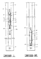
- the preferred embodiment is an apparatus 8 which carries and includes, in the preferred embodiment, an object 10. More specifically, the preferred embodiment of the present invention is a downhole tool which can be dropped down the drill string 6 to the drill bit 4. When it is dropped in the drill string 6, the apparatus 8 descends by free-fall and/or by being pumped with drilling mud or other substance typically circulated through the drill string 6, the drill bit 4 and an annulus 12 defined between the drill string 6 and the well bore 2. The preferred embodiment apparatus 8 will descend until it is stopped upon impact against the drill bit 4 as illustrated in FIG. 2.
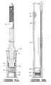
- the embodiment of the apparatus 8 includes the object 10; a housing 14 in which the object 10 is carried; a shock absorber 16 connected to the bottom of the housing 14 so that the shock absorber 16 absorbs shock in response to the apparatus 8 being dropped into the well and the shock absorber 16 engaging the bit 4 which acts as a stop preventing further downward movement of the dropped apparatus 8; other cushioning components 18 located within the housing 14 to further cushion the object 10; centralizers 20 for centralizing the apparatus 8 within the well, and particularly within the drill string 6, and for limiting the terminal velocity at which the apparatus 8 can fall or descend through the drill string 6 and for providing radial shock absorption; and a conventional overshot 22 connected to the top of the housing 14, which overshot 22 permits the apparatus 8 to be retrieved by suitable equipment known in the art.
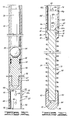
- These components, other than the conventional overshot 22, will be more particularly described with reference to FIGS. 3A-3D.
- the object 10 of the preferred embodiment is an electronic temperature gauge 24.
- An example of a suitable such gauge is the gauge disclosed in U.S. Patent No. 4,665,398 to Lynch et al, which gauge also measures pressure.
- the gauge 24 incluvers an elongated potted electronics package 26 (FIGS. 3A-3B) mechanically and electrically connected to an elongated potted battery package 28 (FIGS. 3B-3C).
- the connections are made through mechanically coupled mating connectors 30 which are extensions from the packages 26, 28.
- the connectors 30 are uncovered to permit a person to make a secure, positive mechanical connection between the two packages 26, 28.
- the electronics package 26 includes the electronics of the gauge 24, and the battery package 28 contains the batteries for energizing the electronics in the package 26. Both the electronics and the batteries are packaged in the same way.
- This packaging includes a cylindrical cardboard tube or sleeve 32 closed at one end by an end piece 34 and at the other end by the respective member of the connectors 30.
- a conventional silicone or other suitable type of potting material 36 is used between the inner diameter of the sleeve 32 and the respective electronics or batteries to secure the respective electronics or batteries within the respective sleeve.
- the potting material is of a type which can be removed to permit the electronics to be accessed if needed.
- Each of the sleeves 32 has an outer diameter substantially the same as the inner diameter of a chamber or cavity 38 defined within the housing 14.
- the chamber 38 of the housing 14 is defined within a cylindrical tubular member 40 (FIGS. 3A-3C) having a length greater than the combined length of the connected electronics package 26 and battery package 28.
- the chamber 38 is pressure-sealed by a top end adapter 41 (FIG. 3A) which carries sealing rings 42, 44 and by a bottom end adapter 46 (FIG. 3C) which carries sealing rings 48, 50.
- the adapters 41, 46 are threaded to mating threads defined at the top and bottom ends, respectively, of the housing tube 40. When so connected, the seal rings 42, 44, 48, 50 seal against the inner surface of the tubular member 40.
- the top end adapter 41 receives the overshot 22, and the bottom end adapter 46 receives the shock absorber 16.
- the shock absorber 16 can be any suitable type, but in the preferred embodiment the shock absorber 16 includes a support body 52 (FIGS. 3C-3D) which supports and receives an elongated member 54 (FIG. 3D).
- the support body 52 can be referred to as a piston housing, and the member 54 can be referred to as a piston.
- the support body 52 includes a cylindrical sleeve 56 which includes a side wall 58 defining, at least in part, a chamber 60.
- An upper end of the sleeve 56 has connected to it by threaded engagement, an end coupling adapter 62 having a threaded bore 64 which receives a threaded extension of the end adapter 46.
- the threaded bore 64 can also selectably couple with a member 54 of another shock absorber 16.
- the support body 52 also includes communication means, defined through the side wall 58, for permitting fluid communication across and along a length of the side wall between the chamber 60 and the exterior of the support body 52.
- the communication means includes a plurality of spaced openings 66 having effective outlet areas which are progressively reduced as the member 54 retracts into the sleeve 56.
- the openings 66 can be slots, holes, or the like, but they are depicted as circular radial holes in the preferred embodiment of FIGS. 3A-3D. In the preferred embodiment, there are at least two openings which are longitudinally spaced from each other so that the progressive area reduction results as the member 54 moves upwardly as depicted in the drawings.
- the member 54 As the member 54 moves upwardly as viewed in the drawings, it pushes fluid, which will be in the chamber 60 when the apparatus 8 is in a well, through at least two openings 66 ahead of it until the member 54 reaches a first one of the two, whereupon continued movement of the member 54 pushes fluid through the second one (and any others still ahead of the member 54) but not the first one (or any others which the member 54 has passed.)
- the effective outlet areas for this direction of movement of the member 54 are defined by any holes 66 which are above a particular position of the upper end of the member 54.
- a position resulting from such upward movement is depicted in FIG. 3D by the dot-dash lines.
- the effective outlet area for this position would include holes 66 shown in FIG. 3C and holes 66h, 66i in FIG. 3D.
- the preferred embodiment communication means specifically includes four sets of longitudinally aligned, but spaced, holes 66. Three of the sets are identified in FIGS. 3C-3D by the reference numerals 68a, 68b, 68c. The fourth set is in the removed section not shown in the drawings; it would lie diametrically opposite the set 68b.
- the sets 68 are circumferentially spaced from each other, and the holes 66 in each set are longitudinally offset from holes in the other sets so that each hole 66 lies on a different respective circumferential plane of the cylindrical side wall 58. As is apparent from FIGS. 3C-3D, this creates a distribution of holes wherein only a single hole at a time is closed as the member 54 progressively retracts.
- the communication means and the side wall 58 can be internal of the shock absorber 16 so that fluid is metered internally. More generally, other types of cushioning or damping can be used.
- the member, or piston, 54 includes a shaft 70 extending from a free end 72 to an enlarged, piston head, end 74 which is housed within the sleeve 56.
- the end 74 includes an annular surface 76 which abuts an annular shoulder 78 at the lower end of the support body 52 when the member 54 is in its fully extended position which is the primary position shown in FIG. 3D.
- the enlarged end 74 moves from this fully extended position where it is spaced from the lowermost hole 66 to a position of retraction, such as depicted by the reference numeral 80, wherein the enlarged end 74 blocks at least a portion of the communication means (e.g., hole 66g, with holes 66a-66f capable of allowing fluid into the chamber 60 behind the end 74, but not used for further cushioning fluid outlet flow for the specific upward stroke of the member 54).
- the communication means e.g., hole 66g, with holes 66a-66f capable of allowing fluid into the chamber 60 behind the end 74, but not used for further cushioning fluid outlet flow for the specific upward stroke of the member 54.
- the shock absorber 16 also includes one or more radial openings 82 defined through the side wall 58 at a location where each opening 82 is adjacent the enlarged end 74 at the fully extended position of the member 54. In the preferred embodiment, this places the opening 82 adjacent the annular shoulder 78 at the lower end of the support body 52. As shown in FIG. 3D, the enlarged end 74 blocks each opening 82 when the member 54 is fully extended. The function of the opening 82 is to receive external fluid when the member 54 retracts, and to flush internal fluid when the member 54 extends. The preferred embodiment positioning of the opening 82 allows complete flushing so that full extension can be obtained.
- the shock absorber 16 also includes a retainer cap 84 which is threadedly connected to the free end 72 of the member 54.
- the retainer 84 includes a face 86 which engages the drill bit 4 (or other structure it encounters) when the shock absorber 16 is to function (i.e. upon impact of the shock absorber 16 against the stopping structure).
- the retainer 84 includes one or more voids or grooves 88 which extend from the face 86 so that the face 86 cannot seal against the stop.
- the shock absorber 16 also includes a spring 90 retained concentrically about the shaft 70 of the member 54 by the retainer cap 84 which is threaded onto the free end 72 of the member 54 after the spring 90 has been received on the shaft 70.
- the other end of the spring 90 abuts an outer annular surface 92 at the bottom end of the support body 52.
- the spring 90 provides a biasing force which tends to move the member 54 to its fully extended position.
- the shock absorber 16 can include additional shock absorber structures connected in series to the shock absorber 16 described hereinabove.
- the retainer cap 84 is unscrewed from the free end 72 of the member 54 and a duplicate shock absorber 16a (FIG. 1) is connected by screwing the free end 72 from which the cap 84 has been removed into the end coupling adapter of the other shock absorber 16a. Additional shock absorbers can be similarly connected.
- shock absorber(s) 16 is(are) the primary cushioning means in the preferred embodiment of the present invention
- other shock absorbing or cushioning is provided by the components 18.
- These include a resilient ball 94 disposed in the pressure-sealed housing 14 between the gauge 24 and the bottom end adapter 46.
- the resilient ball 94 supports the gauge 24 from below, and it prevents or reduces high frequency shock transmissions which might otherwise be passed through the solid structural pieces of the apparatus 8 to the gauge 24 thereof.
- Another additional cushioning component 18 is a spring 96 disposed in the pressure-sealed housing 14 between the gauge 24 and the top end adapter 40.
- the spring 96 sup ports the gauge 24 from above and it takes up any slack to obviate close manufacturing tolerances in the housing 14 and to allow the use of one housing size for different sized objects 10.
- the preferred embodiment of the apparatus 8 also incluvers the centralizers 20.
- the centralizer 98 is retained between the threadedly coupled adapters 46 and 62.
- the centralizer 98 also helps maintain the shock absorber housing 52 spaced from the drill string 6 so that an annular space is maintained between the holes 66 and the inner surface of the drill string 6 for permitting proper fluid flow through the holes 66.
- the centralizer 100 is secured between the threadedly connected adapter 40 and overshot 22. The centralizer 100 also helps maintain the overshot 22 centered within the drill string 6 so that it can be readily engaged by suitable retrieval equipment known in the art.
- the apparatus 8 To use the preferred embodiment of the apparatus 8, it is assembled in the manner illustrated in FIGS. 3A-3D. Once assembled, the apparatus 8 can be dropped down the drill string 6, which dropping can be done in a manner as known in the art.
- the apparatus 8 will fall and/or be pumped downwardly.
- One position of such descent is shown in FIG. 1.
- the apparatus 8 will impact on the drill bit 4.
- the retainer cap 84 will engage the drill bit 4 as shown in FIG. 2.
- the grooves 88 in the cap 84 prevent sealing between the face 86 of the cap 84 and the drill bit 4.
- Chamber 60 of the support body 52 of the shock absorber 16 is filled with fluid against which the enlarged end 74 of the member 54 works as the member 54 relatively retracts into the chamber 60.
- One position of such retraction is identified by the reference numeral 80 in FIG. 3D.
- the chamber 60 is either preloaded with a suitable fluid, such as one with a known viscosity, or simply fills with the fluid within the drill string 6 once the apparatus 8 is dropped into the drill string 6.
- the fluid in the chamber 60 resists or slows the retraction of the member 54, but it yields by flowing out of remaining open ones of the holes 66 in advance of the moving member 54.
- the shock absorption achieved by the preferred embodiment tends to be linearized by the longitudinally off set, non-overlapping layout of the holes 66 previously described.
- the member 54 can return to the fully extended position under the biasing force of the spring 90.
- the electronics and battery packaging is designed to minimize the effects of shock and vibration on the electronic components.
- the pressure-sealed housing 14 protects the thus packaged gauge 24 from the well bore pressure.
- the shock absorber 16 absorbs the shock of the final impact by spreading the impact loading over a longer time span.
- the centralizers 20 maintain a stand-off between the rest of the apparatus 8 and the inner surface of the drill string 6, and they provide drag on the apparatus 8 to reduce the terminal velocity of the apparatus 8. The reduction of terminal velocity reduces the energy the shock absorber 16 has to absorb.
- the centralizers 20 and the components 18 also provide additional shock absorption or cushioning.
Landscapes
- Geology (AREA)
- Life Sciences & Earth Sciences (AREA)
- Engineering & Computer Science (AREA)
- Mining & Mineral Resources (AREA)
- Physics & Mathematics (AREA)
- Environmental & Geological Engineering (AREA)
- Fluid Mechanics (AREA)
- General Life Sciences & Earth Sciences (AREA)
- Geochemistry & Mineralogy (AREA)
- Geophysics (AREA)
- Earth Drilling (AREA)
- Fluid-Damping Devices (AREA)
- Measuring Fluid Pressure (AREA)
Applications Claiming Priority (2)
| Application Number | Priority Date | Filing Date | Title |
|---|---|---|---|
| US07/397,080 US4932471A (en) | 1989-08-22 | 1989-08-22 | Downhole tool, including shock absorber |
| US397080 | 1989-08-22 |
Publications (2)
| Publication Number | Publication Date |
|---|---|
| EP0414334A1 true EP0414334A1 (de) | 1991-02-27 |
| EP0414334B1 EP0414334B1 (de) | 1994-09-21 |
Family
ID=23569761
Family Applications (1)
| Application Number | Title | Priority Date | Filing Date |
|---|---|---|---|
| EP90301800A Expired - Lifetime EP0414334B1 (de) | 1989-08-22 | 1990-02-20 | Stossdämpfer für ein Untertagebohrlochwerkzeug |
Country Status (4)
| Country | Link |
|---|---|
| US (1) | US4932471A (de) |
| EP (1) | EP0414334B1 (de) |
| CA (1) | CA2011139C (de) |
| DE (1) | DE69012717T2 (de) |
Cited By (1)
| Publication number | Priority date | Publication date | Assignee | Title |
|---|---|---|---|---|
| FR2824373A1 (fr) * | 2001-05-03 | 2002-11-08 | Sondex Ltd | Appareil amortisseur de choc |
Families Citing this family (41)
| Publication number | Priority date | Publication date | Assignee | Title |
|---|---|---|---|---|
| GB2231070B (en) * | 1989-04-29 | 1992-07-29 | Baroid Technology Inc | Down-hole decelerators |
| DE4129709C1 (de) * | 1991-09-06 | 1992-12-03 | Bergwerksverband Gmbh | |
| US5320169A (en) * | 1992-12-14 | 1994-06-14 | Panex Corporation | Gauge carrier |
| EP0658683A1 (de) * | 1993-12-17 | 1995-06-21 | Cooper Cameron Corporation | Einführungswerkzeug |
| US5520246A (en) * | 1994-11-14 | 1996-05-28 | Scientific Drilling International | Multi-mode cushioning an instrument suspended in a well |
| CA2141086A1 (en) * | 1995-01-25 | 1996-07-26 | Gerhard Herget | Rock extensometer |
| US6412614B1 (en) | 1999-09-20 | 2002-07-02 | Core Laboratories Canada Ltd. | Downhole shock absorber |
| US6536519B1 (en) * | 2000-10-13 | 2003-03-25 | Schlumberger Technology Corp. | Downhole tool to generate tension pulses on a slickline |
| US6708761B2 (en) | 2001-11-13 | 2004-03-23 | Halliburton Energy Services, Inc. | Apparatus for absorbing a shock and method for use of same |
| US6761230B2 (en) * | 2002-09-06 | 2004-07-13 | Schlumberger Technology Corporation | Downhole drilling apparatus and method for using same |
| US7090010B1 (en) | 2003-09-25 | 2006-08-15 | Todd Martin | Gauge carrier sub apparatus |
| US20060118297A1 (en) * | 2004-12-07 | 2006-06-08 | Schlumberger Technology Corporation | Downhole tool shock absorber |
| US7779907B2 (en) * | 2008-03-25 | 2010-08-24 | Baker Hughes Incorporated | Downhole shock absorber with crushable nose |
| US9523270B2 (en) * | 2008-09-24 | 2016-12-20 | Halliburton Energy Services, Inc. | Downhole electronics with pressure transfer medium |
| US8011428B2 (en) * | 2008-11-25 | 2011-09-06 | Baker Hughes Incorporated | Downhole decelerating device, system and method |
| US20100132957A1 (en) * | 2008-12-02 | 2010-06-03 | Baker Hughes Incorporated | Downhole shape memory alloy actuator and method |
| US8604634B2 (en) * | 2009-06-05 | 2013-12-10 | Schlumberger Technology Corporation | Energy harvesting from flow-induced vibrations |
| US9816533B2 (en) | 2011-07-06 | 2017-11-14 | Kelvin FALK | Jet pump data tool system |
| US9004183B2 (en) | 2011-09-20 | 2015-04-14 | Baker Hughes Incorporated | Drop in completion method |
| US8813876B2 (en) | 2011-10-18 | 2014-08-26 | Schlumberger Technology Corporation | Downhole tool impact dissipating tool |
| US8820402B2 (en) | 2012-01-09 | 2014-09-02 | Baker Hughes Incorporated | Downhole shock absorber with guided crushable nose |
| US9624996B2 (en) * | 2015-01-15 | 2017-04-18 | Flowco Production Solutions, LLC | Robust bumper spring assembly |
| CA2918007C (en) * | 2015-01-15 | 2022-10-18 | Flowco Production Solutions, LLC | Robust bumper spring assembly |
| US9963957B2 (en) | 2015-02-20 | 2018-05-08 | Flowco Production Solutions, LLC | Clutch assembly for bypass plungers |
| CA2921175C (en) | 2015-02-20 | 2023-09-26 | Flowco Production Solutions, LLC | Improved dart valves for bypass plungers |
| US10669824B2 (en) | 2015-02-20 | 2020-06-02 | Flowco Production Solutions, LLC | Unibody bypass plunger and valve cage with sealable ports |
| US11578570B2 (en) * | 2015-02-20 | 2023-02-14 | Flowco Production Solutions, LLC | Unibody bypass plunger and valve cage with sealable ports |
| US10221849B2 (en) | 2015-05-18 | 2019-03-05 | Patriot Artificial Lift, LLC | Forged flange lubricator |
| US10161230B2 (en) | 2016-03-15 | 2018-12-25 | Patriot Artificial Lift, LLC | Well plunger systems |
| CA3093112C (en) | 2018-03-06 | 2023-09-05 | Flowco Production Solutions, LLC | Internal valve plunger |
| US20220056785A1 (en) * | 2018-09-13 | 2022-02-24 | Flowco Production Solutions, LLC | Unibody bypass plunger with integral dart valve cage |
| US11293267B2 (en) | 2018-11-30 | 2022-04-05 | Flowco Production Solutions, LLC | Apparatuses and methods for scraping |
| USD937982S1 (en) | 2019-05-29 | 2021-12-07 | Flowco Production Solutions, LLC | Apparatus for a plunger system |
| US11448049B2 (en) | 2019-09-05 | 2022-09-20 | Flowco Production Solutions, LLC | Gas assisted plunger lift control system and method |
| US12680428B2 (en) | 2019-09-18 | 2026-07-14 | Flowco Masterco Llc | Unibody shift rod plunger |
| CA3097855A1 (en) * | 2019-11-25 | 2021-05-25 | Extensive Energy Technologies Partnership | Downhole vibration and shock absorbing device |
| SA121420921B1 (ar) * | 2020-12-17 | 2024-03-17 | شلمبيرجر تكنولوجي بي. في | أداة ابطاء حفر حفرة بئر هيدروليكية |
| CN112943113B (zh) * | 2021-01-28 | 2023-01-20 | 成都希能能源科技有限公司 | 一种近钻头减震工具 |
| CN112832704B (zh) * | 2021-01-29 | 2024-06-21 | 成都维锐泰达能源技术有限公司 | 用于泵送智能开启装置的减震扶正装置、智能开启装置及多级压裂智能控制系统 |
| US12404733B2 (en) * | 2023-10-03 | 2025-09-02 | Scientific Drilling International, Inc. | Drop tool impact shock mitigation with fluid retention method and system |
| CN117738596B (zh) * | 2024-02-19 | 2024-04-16 | 成都之恒油气技术开发有限公司 | 一种井下振动缓冲型钻井工具 |
Citations (2)
| Publication number | Priority date | Publication date | Assignee | Title |
|---|---|---|---|---|
| DD207237A5 (de) * | 1982-02-05 | 1984-02-22 | Dailey Oil Tools Inc | Bohrlochwerkzeug |
| EP0173922A1 (de) * | 1984-09-06 | 1986-03-12 | Secoroc AB | Verbindungsvorrichtung in Verlängerungsbohrgestängen für schlagendes Bohren |
Family Cites Families (11)
| Publication number | Priority date | Publication date | Assignee | Title |
|---|---|---|---|---|
| US2176766A (en) * | 1936-11-20 | 1939-10-17 | Mordica O Johnston | Pressure bomb mounting |
| US2576924A (en) * | 1948-05-11 | 1951-12-04 | Dresser Equipment Company | Fluid operated pump with hydraulic shock absorber |
| US2577599A (en) * | 1948-08-03 | 1951-12-04 | Sun Oil Co | Shockproof case for borehole measuring instruments |
| US3381780A (en) * | 1966-04-01 | 1968-05-07 | Schlumberger Technology Corp | Well tool shock absorber |
| US4057129A (en) * | 1976-06-28 | 1977-11-08 | Hennells Ransom J | Self adjusting energy absorber employing conical control sleeve |
| US4149593A (en) * | 1977-12-27 | 1979-04-17 | Otis Engineering Corporation | Well testing tool system |
| US4223746A (en) * | 1979-01-29 | 1980-09-23 | Schlumberger Technology Corporation | Shock limiting apparatus |
| US4585099A (en) * | 1984-01-10 | 1986-04-29 | Tayco Developments, Inc. | Molded plastic cylinder for energy absorbers, fluid cylinders, and the like |
| US4665398A (en) * | 1985-05-06 | 1987-05-12 | Halliburton Company | Method of sampling and recording information pertaining to a physical condition detected in a well bore |
| US4693317A (en) * | 1985-06-03 | 1987-09-15 | Halliburton Company | Method and apparatus for absorbing shock |
| US4679669A (en) * | 1985-09-03 | 1987-07-14 | S.I.E., Inc. | Shock absorber |
-
1989
- 1989-08-22 US US07/397,080 patent/US4932471A/en not_active Expired - Lifetime
-
1990
- 1990-02-20 EP EP90301800A patent/EP0414334B1/de not_active Expired - Lifetime
- 1990-02-20 DE DE69012717T patent/DE69012717T2/de not_active Expired - Fee Related
- 1990-02-28 CA CA002011139A patent/CA2011139C/en not_active Expired - Fee Related
Patent Citations (2)
| Publication number | Priority date | Publication date | Assignee | Title |
|---|---|---|---|---|
| DD207237A5 (de) * | 1982-02-05 | 1984-02-22 | Dailey Oil Tools Inc | Bohrlochwerkzeug |
| EP0173922A1 (de) * | 1984-09-06 | 1986-03-12 | Secoroc AB | Verbindungsvorrichtung in Verlängerungsbohrgestängen für schlagendes Bohren |
Cited By (3)
| Publication number | Priority date | Publication date | Assignee | Title |
|---|---|---|---|---|
| FR2824373A1 (fr) * | 2001-05-03 | 2002-11-08 | Sondex Ltd | Appareil amortisseur de choc |
| WO2002090715A1 (en) | 2001-05-03 | 2002-11-14 | Sondex Limited | Shock absorber |
| US7044219B2 (en) | 2001-05-03 | 2006-05-16 | Sondex Limited | Shock absorber |
Also Published As
| Publication number | Publication date |
|---|---|
| CA2011139A1 (en) | 1991-02-22 |
| US4932471A (en) | 1990-06-12 |
| EP0414334B1 (de) | 1994-09-21 |
| DE69012717T2 (de) | 1995-02-09 |
| DE69012717D1 (de) | 1994-10-27 |
| CA2011139C (en) | 1994-10-18 |
Similar Documents
| Publication | Publication Date | Title |
|---|---|---|
| EP0414334B1 (de) | Stossdämpfer für ein Untertagebohrlochwerkzeug | |
| US5083623A (en) | Hydraulic shock absorber | |
| US3998443A (en) | Multidirectional shock absorbing device | |
| US6454012B1 (en) | Tool string shock absorber | |
| US5181565A (en) | Well probe able to be uncoupled from a rigid coupling connecting it to the surface | |
| US4693317A (en) | Method and apparatus for absorbing shock | |
| CA2966920C (en) | Vibration dampener | |
| US4901806A (en) | Apparatus for controlled absorption of axial and torsional forces in a well string | |
| CA1094948A (en) | Self-adjusting liquid spring operating apparatus and method for use in an oil well valve | |
| US5133419A (en) | Hydraulic shock absorber with nitrogen stabilizer | |
| CA2259852C (en) | Wireless coiled tubing joint locator | |
| US3963228A (en) | Drill string shock absorber | |
| US4223746A (en) | Shock limiting apparatus | |
| US4979563A (en) | Offset shock mounted recorder carrier including overpressure gauge protector and balance joint | |
| GB2170528A (en) | Casing extender | |
| CA2766168A1 (en) | Hydraulically locking stabilizer | |
| CA1114360A (en) | Temperature compensating hydraulic jarring tool | |
| CA2851823A1 (en) | Downhole tool impact dissipating tool | |
| AU2026202842A1 (en) | Shock absorber for a downhole tool, and running gear for downhole surveying | |
| US4681160A (en) | Apparatus for securing a measurement-while-drilling (MWD) instrument within a pipe | |
| RU2259466C1 (ru) | Пакер-пробка | |
| CA1130781A (en) | Drill string shock absorbr with pressurized lubricant system | |
| US12454884B2 (en) | Downhole tool assemblies | |
| US2819878A (en) | Suspension drilling device and jar | |
| SU1078043A1 (ru) | Устройство дл регистрации гидродинамического давлени и осевой нагрузки |
Legal Events
| Date | Code | Title | Description |
|---|---|---|---|
| PUAI | Public reference made under article 153(3) epc to a published international application that has entered the european phase |
Free format text: ORIGINAL CODE: 0009012 |
|
| AK | Designated contracting states |
Kind code of ref document: A1 Designated state(s): DE FR GB IT NL |
|
| 17P | Request for examination filed |
Effective date: 19910816 |
|
| 17Q | First examination report despatched |
Effective date: 19930126 |
|
| GRAA | (expected) grant |
Free format text: ORIGINAL CODE: 0009210 |
|
| ITF | It: translation for a ep patent filed | ||
| AK | Designated contracting states |
Kind code of ref document: B1 Designated state(s): DE FR GB IT NL |
|
| REF | Corresponds to: |
Ref document number: 69012717 Country of ref document: DE Date of ref document: 19941027 |
|
| ET | Fr: translation filed | ||
| PGFP | Annual fee paid to national office [announced via postgrant information from national office to epo] |
Ref country code: GB Payment date: 19950210 Year of fee payment: 6 Ref country code: FR Payment date: 19950210 Year of fee payment: 6 |
|
| PGFP | Annual fee paid to national office [announced via postgrant information from national office to epo] |
Ref country code: DE Payment date: 19950222 Year of fee payment: 6 |
|
| PGFP | Annual fee paid to national office [announced via postgrant information from national office to epo] |
Ref country code: NL Payment date: 19950228 Year of fee payment: 6 |
|
| PLBE | No opposition filed within time limit |
Free format text: ORIGINAL CODE: 0009261 |
|
| STAA | Information on the status of an ep patent application or granted ep patent |
Free format text: STATUS: NO OPPOSITION FILED WITHIN TIME LIMIT |
|
| 26N | No opposition filed | ||
| PG25 | Lapsed in a contracting state [announced via postgrant information from national office to epo] |
Ref country code: GB Effective date: 19960220 |
|
| PG25 | Lapsed in a contracting state [announced via postgrant information from national office to epo] |
Ref country code: NL Effective date: 19960901 |
|
| GBPC | Gb: european patent ceased through non-payment of renewal fee |
Effective date: 19960220 |
|
| PG25 | Lapsed in a contracting state [announced via postgrant information from national office to epo] |
Ref country code: FR Effective date: 19961031 |
|
| NLV4 | Nl: lapsed or anulled due to non-payment of the annual fee |
Effective date: 19960901 |
|
| PG25 | Lapsed in a contracting state [announced via postgrant information from national office to epo] |
Ref country code: DE Effective date: 19961101 |
|
| REG | Reference to a national code |
Ref country code: FR Ref legal event code: ST |
|
| PG25 | Lapsed in a contracting state [announced via postgrant information from national office to epo] |
Ref country code: IT Free format text: LAPSE BECAUSE OF NON-PAYMENT OF DUE FEES;WARNING: LAPSES OF ITALIAN PATENTS WITH EFFECTIVE DATE BEFORE 2007 MAY HAVE OCCURRED AT ANY TIME BEFORE 2007. THE CORRECT EFFECTIVE DATE MAY BE DIFFERENT FROM THE ONE RECORDED. Effective date: 20050220 |