EP0414380B1 - Gerät zur optischen Aufnahme und Wiedergabe und Adaptor zum Gebrauch mit diesem Gerät - Google Patents
Gerät zur optischen Aufnahme und Wiedergabe und Adaptor zum Gebrauch mit diesem Gerät Download PDFInfo
- Publication number
- EP0414380B1 EP0414380B1 EP90308038A EP90308038A EP0414380B1 EP 0414380 B1 EP0414380 B1 EP 0414380B1 EP 90308038 A EP90308038 A EP 90308038A EP 90308038 A EP90308038 A EP 90308038A EP 0414380 B1 EP0414380 B1 EP 0414380B1
- Authority
- EP
- European Patent Office
- Prior art keywords
- optical
- optical length
- data recording
- data
- optical disk
- Prior art date
- Legal status (The legal status is an assumption and is not a legal conclusion. Google has not performed a legal analysis and makes no representation as to the accuracy of the status listed.)
- Expired - Lifetime
Links
Images




Classifications
-
- G—PHYSICS
- G11—INFORMATION STORAGE
- G11B—INFORMATION STORAGE BASED ON RELATIVE MOVEMENT BETWEEN RECORD CARRIER AND TRANSDUCER
- G11B7/00—Recording or reproducing by optical means, e.g. recording using a thermal beam of optical radiation by modifying optical properties or the physical structure, reproducing using an optical beam at lower power by sensing optical properties; Record carriers therefor
- G11B7/12—Heads, e.g. forming of the optical beam spot or modulation of the optical beam
- G11B7/135—Means for guiding the beam from the source to the record carrier or from the record carrier to the detector
- G11B7/1392—Means for controlling the beam wavefront, e.g. for correction of aberration
- G11B7/13925—Means for controlling the beam wavefront, e.g. for correction of aberration active, e.g. controlled by electrical or mechanical means
-
- G—PHYSICS
- G11—INFORMATION STORAGE
- G11B—INFORMATION STORAGE BASED ON RELATIVE MOVEMENT BETWEEN RECORD CARRIER AND TRANSDUCER
- G11B7/00—Recording or reproducing by optical means, e.g. recording using a thermal beam of optical radiation by modifying optical properties or the physical structure, reproducing using an optical beam at lower power by sensing optical properties; Record carriers therefor
- G11B7/08—Disposition or mounting of heads or light sources relatively to record carriers
- G11B7/09—Disposition or mounting of heads or light sources relatively to record carriers with provision for moving the light beam or focus plane for the purpose of maintaining alignment of the light beam relative to the record carrier during transducing operation, e.g. to compensate for surface irregularities of the latter or for track following
- G11B7/0945—Methods for initialising servos, start-up sequences
-
- G—PHYSICS
- G11—INFORMATION STORAGE
- G11B—INFORMATION STORAGE BASED ON RELATIVE MOVEMENT BETWEEN RECORD CARRIER AND TRANSDUCER
- G11B7/00—Recording or reproducing by optical means, e.g. recording using a thermal beam of optical radiation by modifying optical properties or the physical structure, reproducing using an optical beam at lower power by sensing optical properties; Record carriers therefor
- G11B7/12—Heads, e.g. forming of the optical beam spot or modulation of the optical beam
- G11B7/135—Means for guiding the beam from the source to the record carrier or from the record carrier to the detector
- G11B7/1365—Separate or integrated refractive elements, e.g. wave plates
- G11B7/1369—Active plates, e.g. liquid crystal panels or electrostrictive elements
-
- G—PHYSICS
- G11—INFORMATION STORAGE
- G11B—INFORMATION STORAGE BASED ON RELATIVE MOVEMENT BETWEEN RECORD CARRIER AND TRANSDUCER
- G11B11/00—Recording on or reproducing from the same record carrier wherein for these two operations the methods are covered by different main groups of groups G11B3/00 - G11B7/00 or by different subgroups of group G11B9/00; Record carriers therefor
- G11B11/10—Recording on or reproducing from the same record carrier wherein for these two operations the methods are covered by different main groups of groups G11B3/00 - G11B7/00 or by different subgroups of group G11B9/00; Record carriers therefor using recording by magnetic means or other means for magnetisation or demagnetisation of a record carrier, e.g. light induced spin magnetisation; Demagnetisation by thermal or stress means in the presence or not of an orienting magnetic field
- G11B11/105—Recording on or reproducing from the same record carrier wherein for these two operations the methods are covered by different main groups of groups G11B3/00 - G11B7/00 or by different subgroups of group G11B9/00; Record carriers therefor using recording by magnetic means or other means for magnetisation or demagnetisation of a record carrier, e.g. light induced spin magnetisation; Demagnetisation by thermal or stress means in the presence or not of an orienting magnetic field using a beam of light or a magnetic field for recording by change of magnetisation and a beam of light for reproducing, i.e. magneto-optical, e.g. light-induced thermomagnetic recording, spin magnetisation recording, Kerr or Faraday effect reproducing
-
- G—PHYSICS
- G11—INFORMATION STORAGE
- G11B—INFORMATION STORAGE BASED ON RELATIVE MOVEMENT BETWEEN RECORD CARRIER AND TRANSDUCER
- G11B7/00—Recording or reproducing by optical means, e.g. recording using a thermal beam of optical radiation by modifying optical properties or the physical structure, reproducing using an optical beam at lower power by sensing optical properties; Record carriers therefor
- G11B2007/0003—Recording, reproducing or erasing systems characterised by the structure or type of the carrier
- G11B2007/0006—Recording, reproducing or erasing systems characterised by the structure or type of the carrier adapted for scanning different types of carrier, e.g. CD & DVD
-
- G—PHYSICS
- G11—INFORMATION STORAGE
- G11B—INFORMATION STORAGE BASED ON RELATIVE MOVEMENT BETWEEN RECORD CARRIER AND TRANSDUCER
- G11B7/00—Recording or reproducing by optical means, e.g. recording using a thermal beam of optical radiation by modifying optical properties or the physical structure, reproducing using an optical beam at lower power by sensing optical properties; Record carriers therefor
- G11B2007/0003—Recording, reproducing or erasing systems characterised by the structure or type of the carrier
- G11B2007/0009—Recording, reproducing or erasing systems characterised by the structure or type of the carrier for carriers having data stored in three dimensions, e.g. volume storage
- G11B2007/0013—Recording, reproducing or erasing systems characterised by the structure or type of the carrier for carriers having data stored in three dimensions, e.g. volume storage for carriers having multiple discrete layers
Definitions
- the present invention relates to an optical recording/reproducing apparatus and an adaptor for run with this apparatus.
- optical disk apparatuses There are three different operational types of the disk apparatuses: a read-only type apparatus, e.g. a popular compact disk player or a laser disk player; a write-once-read-many type apparatus for handling e.g. document files or data files; and a rewritable optical disk apparatus.
- a read-only type apparatus e.g. a popular compact disk player or a laser disk player
- a write-once-read-many type apparatus for handling e.g. document files or data files
- rewritable optical disk apparatus e.g. a rewritable optical disk apparatus.
- each disk substrate is commonly about 1.2 mm in thickness.
- an objective lens is employed which has a large numerical aperture for convergence of light close to the limit of wavelength diffraction and can focus behind the disk substrate without aberration.
- the substrate preferably has a specific thickness.
- a known optical disk is at least 3.5 inches in diameter. However, it is much desired to reduce not only the diameter of the substrate but also the thickness for the purpose of improving the portability and minimizing the installation area of an optical disk recording/reproducing apparatus. To play beck a disk having such a thinner substrate, the playback device needs to have a specified objective lens corresponding to the thickness of the substrate from the reason described previously. Then, the problem arises that a conventional optical disk cannot be played back with the arrangement of such a modified optical system.
- multi-layer optical disks having a plurality of date layers.
- U.S.Patent 3,999,009 is shown in Fig.8 in which a detachable transparent plate 9 is provided between a recording medium and an objective lens 8 for displacing the focal point of the objective lens for reproduction of data from an arbitrary data layer. More particularly, the focusing is made on an objective lens side one 2a of the two data layers 2a and 2b provided on both sides of a substrate 1 with the absence of the transparent plate 9 (Fig. 8-a) and on the other data layer 2b when the transparent plate 9 is mounted in place (Fig.8-b).
- the transparent plate 9 is employed only for increasing the focal length of the objective lens 8 and no aberration of the lens 8 is regarded. In fact, even if the convergence of light is established close to the limit of diffraction as shown in Fig.8a, the use of the transparent plate 9 causes aberration due to a difference in the light path distance across the objective lens 8 and the substrate 1, thus increasing the size of a light spot. Because the light spots on the data layers are different in aberration. the recording of data onto the data layers of the optical disk should be carried out by changing the recording density of data in response to the size of each light spot on the corresponding data layer. The disadvantage is that when the number of data layers is increased the recording density becomes decreased.
- a first object of the present invention to provide an apparatus capable of reproducing data from different optical data recording mediums whose substrates are different in thickness from each other.
- the present invention provides an optical data recording/reproducing apparatus for recording and reproducting data on an optical data recording medium having a data recording layer disposed on a transparent substrate thereof, the apparatus comprising:
- an optical distance between the objective lens and the recording surface of the data recording layer medium remains constant allowing a light spot to be established with less aberration on a data recording layer of the optical recording medium.
- the reproduction of data is possible from various optical disks whose substrates are different in thickness from each other.
- the apparatus can be modified to record data signals on and reproduce data signals from a recording medium having at least two data recording layers with less optical aberration.
- Such an arrangement comprises a light source, an objective lens capable of focusing behind a planar plate having a specific optical length and converging a light beam from the light source on any data recording layer of an optical recording medium, an optical length correcting means provided between the objective lens and the optical recording medium and having at least two different optical lengths. and a photo-detector for detecting a reflected or transmitted light from the recording medium so that a desired optical length of the optical length correcting means can be determined corresponding to the location of the data layer.
- a light spot with less aberration will be established on an arbitrary data layer of the optical recording medium.
- Fig.1 illustrates an optical data recording/reproducing apparatus according to the present invention.
- an optical disk 100 having a data layer 2 disposed on a transparent substrate 1.
- the data layer 2 incorporates pits arranged thereon corresponding to data signals or patterns of optical density variations or magnetization changes developed thereon.
- a light source, or laser diode, 3 which emits light of 830 nm wavelength is used.
- the light emitted from the laser diode 3 after modulation with a laser driver 4 is shifted by a collimator lens 5 to a parallel beam which is then reflected by a polarized beam splitter 6 and passes across a 1/4 wave plate 7 to an objective lens 8 and an optical length correcting transparent plate 9 before converging on the data layer 2 of the optical disk.
- the objective lens 8 is arranged to focus the light beam on the data layer 2, without the transparent plate 9, when the optical length of the transparent substrate 1 of the optical disk 100 is equal to a predetermined optical length.
- the transparent plate 9 is placed across the light path between the objective lens 8 and the optical disk 100.
- the optical length of the transparent plate 9 is equal to a difference between the optical length of the transparent substrate 1 and the predetermined optical length.
- the transparent plate 9 is actuated by a plate actuator 11 for moving into and withdrawing from the light path according to information of the substrate thickness detected by a disk shape detector 10.
- the light reflected on the data layer 2 then passes in sequence the transparent plate 9, the objective lens 8, the 1/4 wave plate 7, the polarized beam splitter 6, and a lens 12 to a mirror 13. Then, a portion of the light reflected from the mirror 13 enters a focus control photodetector 14 having two separate sensor areas for focus control, while the remaining light goes straight to a two-sensor photodetector 15 for tracking control and data reproduction.
- the corresponding signals from the two photodetectors 14 and 15 are transmitted to a signal reproduction controller 16 where they are turned to a reproduced data signal and a control signal: the latter actuates a voice coil 17 for focusing and tracking control so that the focal point of the objective lens 8 goes to a target data pattern on the data layer 2.
- the optical system may be modified for detection of variations in the magnetization by means of a magneto-optical effect, in which the polarized beam splitter 6 and mirror 13 are replaced with a half mirror and a large-size polarized beam splitter respectively.
- the substrate of the optical disk may be made of a resin material, e.g. polycarbonate and polymethyl- methacrylate (PMMA), or glass.
- a resin material e.g. polycarbonate and polymethyl- methacrylate (PMMA), or glass.
- the transparent plate 9 is preferably such that both incident and emerging surfaces thereof are approximately parallel to each other, the transmittance is high at the wavelength of the incident light, and the refractive index at the wavelength of the incident light is equal to that of the substrate of the optical disk. Also, its material can be selected from glass and synthetic resin. A reflection prevention layer may additionally be provided on either or both the incident and emerging surfaces of the transparent plate for increasing the transmittance efficiency of the incident light, thus ensuring the efficient use of the output of the laser diode.
- the objective lens employed in the optical disk apparatus is designed for corresponding to the wavelength of the laser light used and allowing the light beam to focus through the substrate having a specific optical length, e.g. 1.2 mm (with less effects of various aberrations).
- a commonly available standard optical disk incorporates a transparent substrate having such a specific optical length.
- a particular transparent plate is employed such that the total thickness of the substrate and the transparent plate becomes 1.2 mm. For example, if the thickness of the optical disk substrate 1 is 0.8 mm, the transparent plate 9 having a thickness of 0.4 mm may be used.
- the optical length from the objective lens 8 to the data layer 2 is recovered to equal to the original length with the standard optical disk, ensuring the convergence of light with less optical error such as spherical aberration.
- the transparent plate can be installed upon detecting, with the disk shape detector 10, the thickness of an optical disk inserted into the optical disk recording/reproducing apparatus.
- the thickness of an optical disk may also be identified by reading a marking of thickness which has been formed on the disk or a cartridge of the disk. According to the information given by calculating the difference between the thickness of the optical disk and a thickness of a reference substrate which has been predetermined according to the design conditions of the objective lens, the controller 16 actuates the plate actuator 11 to set the transparent plate 9 of a desired thickness across the light path.
- a particular shape of the transparent plate 9 can be provided as shown in Fig.2.
- the plates are shaped so that the optical length thereof can be varied with or without steps: the optical length may vary continuously (Figs.2-a and 2-b) and in steps (Fig.2-c).
- the plates may be adapted for rotating movement (Fig.2-a) or for linear movement (Figs.2-b and 2-c).
- a plurality of transparent plates may be provided for use in combination, as shown in Fig.2-d.
- the arrow mark in Fig.2 represent the direction of the movement of the transparent plate.
- the focus control is first made using the transparent plate situated at a proper location and a reproduced signal from the optical disk is detected. Then, while the transparent plate is rotated or linearly displaced, the amplitude of the signal is examined. When the signal amplitude reaches a maximum, the transparent plate is fixed at the position.
- the optical disk For constant positioning of the transparent plate, it is desired that the optical disk carries a signal recorded on a specified location thereof for control of the transparent plate thickness.
- the address or clock signal section for control of data signals where a pattern of the control signal is duly identified, can be utilized for the purpose. In this manner, data signals on the optical disk will be read by the optimum focusing for reproduction.
- This procedure is also applicable to an optical disk apparatus in which the thickness of each disk can be identified from its cartridge or the like and different type optical disks can be played back.
- the transparent plate 9 is removed by the plate actuator 11 from the optical path between the disk and the objective lens 8.
- the transparent plate 9 is inserted between the disk and the objective lens 8 by the plate actuator 11. The thickness of the transparent plate 9 should correspond to that of a different optical disk to be read.
- the foregoing description is made with reference to a data layer carrying recorded data. If the data layer is capable of writing and reading, the recording of data is carried out by feeding data signals to be recorded from the outside and in response to the input signals, modulating the output of the laser diode with the laser driver circuit 4.
- the recording or reproduction from various optical disks which are different in thickness from each other can be executed and an apparatus for the recording and reproduction will be feasible.
- the transparent plate is provided as a primary component in the optical playback system as described in Embodiment 1, the present invention resides in any medium which can complement the thickness of a substrate of an optical disk between the objective lens and the optical disk.
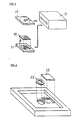
- the application of such a transparent plate to an optical disk in a prior art optical playback system will now be described referring to Figs.3, 4, and 5.
- a known optical disk cartridge 19 carrying an optical disk therein is inserted into a conventional playback device 18 for setting to a disk motor, prior to reproduction of data from the optical disk.
- a small-sized optical disk cartridge 20 incorporating a thinner substrate is accommodated in a conversion adapter 21 which has a size equal to the known optical disk cartridge 19 for reproduction with the conventional playback device 18.
- the conversion adapter 21 is shown in more detail in Fig.4.
- the conversion adapter 21 is provided with a transparent plate 22 for complement to the thickness of the optical disk and at the central region, a spacer ring 23 for complement to the thickness of the substrate of the optical disk.
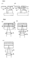
- Figs.5-a and 5-b are cross sectional views showing an optical disk of 1.2 mm thick loaded and a thinner disk loaded with the help of the spacer ring 23 in a playback device respectively, in which other components including a casing of the cartridge are not shown.
- the spacer ring 23 mounted on a disk motor shaft 24 raises the thinner disk 25 allowing the distance between the data layer 2 and the objective lens 8 to be the same as with a conventional optical disk.
- any thinner optical disk can be played back by a conventional playback device with the use of a conversion adapter.
- an optical disk having a plurality of data recording layers can be played back using a transparent plate interposed between the objective lens and the optical disk for shifting the focal position of a light spot.
- a multilayer optical disk 26 has three data layers 28, 29, and 30 disposed on a substrate 27 thereof and separated by transparent partition layers 31 and 32 respectively.
- the transparent partition layers 31 and 32 are each preferably made of a resin material, e.g. polycarbonate or polymethylmethacrylate (PMMA), or glass, having a property of high transmission at the wavelength of light used.
- Any data layer can be selected by setting a corresponding transparent plate between the objective lens and the optical disk: with no use of any transparent plate, data on the third data layer 30 is reproduced with focusing the objective lens (Fig.6-a); data on the second data layer 29 is reproduced with a transparent plate 33 interposed between the objective lens and the optical disk for deflecting light to focus on the data surface of the layer 29 (Fig.6-b); and data on the first layer 28 is reproduced with the use of a thicker transparent plate 34 allowing the focal point to be located near the surface of the substrate.
- each data layer is determined so that the total thickness of the transparent plate, disk substrate, and transparent partition layer(s) is 1.2 mm between the objective lens and the target data layer.
- the thickness of the data layer 28, 29, or 30 is as small as less than 1 ⁇ m, compared with that of the other layers.
- the thickness of each of the transparent partition layers 31 and 32 is 100 ⁇ m
- the two transparent plates are 100 ⁇ m and 200 ⁇ m in thickness and the substrate of the optical disk has a thickness of 1 mm.
- the disk substrate, transparent partition layers, transparent plates are the same in the refractive index so that the optimum convergence of light can be ensured.
- the light absorption of each data layer is 20%.
- Fig.7 illustrates a focus error signal (Fig.7-a) and a reproduced signal amplitude (Fig.7-b) varying as the objective lens is displaced towards and then away from the substrate of the optical disk.
- Fig.7-a Three of S-shaped error signs corresponding to their respective three data layers are shown in Fig.7-a.
- corresponding amplitude faults to the S-shaped errors in the focus error signal appear in the reproduced signal as shown in Fig.7-b.
- the focusing onto the second data layer will be accomplished.
- the focusing is carried out upon detecting the third S-shaped error with a 200 ⁇ m-thick transparent plate employed.
- the focusing is made upon detecting the first S-shaped error with no use of the transparent plate.
- the incident light beam tends to be refracted due to the recording variations on the data layer(s) existing in the incident light side.
- the portion of the light beam refracted at the first data layer is diffused before reaching the second data layer and after reflected, will be averaged until it affects on a detector for reproduction, increasing the noise in general term but not distorting the reproduced signal.
- the reproduction of data from the data layers can be made.
- the data layers may be provided in the form of pit arrangements, e.g. on a compact disc, perforated thin films, variations in the amorphous crystalline state, magne-to-optical recording layers for reproduction of signals from a magnetic medium by means of magneto-optical effects, or a combination thereof.
- a magneto-optical recording layer as the first layer and other non-magneto-optical data layers is employed, the refraction of incident light beams can be disregarded because the first data layer causes the polarization of light to be slightly diverted. Hence, the interference to the signals on the second and following layers will be minimized. Accordingly, the reproduction of data from the multi-layer optical disk can be realized and the recording data capacity of each optical disk will thus be increased.
- Embodiments 1, 2, and 3 are described in the respect of reproducing signals, the present invention will afford equal success in recording, erase, and over-writing of signals.
Landscapes
- Physics & Mathematics (AREA)
- Optics & Photonics (AREA)
- Chemical & Material Sciences (AREA)
- Crystallography & Structural Chemistry (AREA)
- Optical Recording Or Reproduction (AREA)
- Optical Head (AREA)
- Optical Record Carriers And Manufacture Thereof (AREA)
Claims (9)
- Aufzeichnungs-/Wiedergabegerät für optische Daten zur Aufzeichnung und Wiedergabe von Daten auf bzw. von einem Aufzeichnungsmedium für optische Daten (100), welches eine Datenaufzeichnungsschicht (2) auf ihrem transparenten Substrat (1) aufweist, wobei das Gerät umfaßt:eine Lichtquelle (3) zum Aussenden eines Lichtstrahls,eine Objektivlinse (8) zum Bündeln des Lichtstrahls von der Lichtquelle undeine Positioniereinrichtung für das Aufzeichnungsmedium für optische Daten, so daß dessen Datenaufzeichnungsschicht in eine vorgegebene Position gebracht wird,wobei die Objektivlinse (8) so angeordnet ist, daß sie während des Betriebs den Lichtstrahl durch das transparente Substrat eines Aufzeichnungsmediums für optische Daten, welches von der Positioniereinrichtung eingesetzt wurde, bündelt und somit einen Brennpunkt auf der Datenaufzeichnungsschicht bildet, wenn das transparente Substrat eine vorgegebene optische Länge hat;und das Gerät weiterhin umfaßt: einen Fotodetektor (14, 15) zum Erfassen des Lichts, das während des Betriebs durch das Aufzeichhungsmedium durchgelassen oder von ihm reflektiert wurde, undeine Korrektureinrichtung (9) für die optische Länge während des Betriebs, die zwischen der Objektivlinse und der vorgegebenen Position angebracht ist,wobei die Korrektureinrichtung für die optische Länge eine optische Länge aufweist, die der Differenz zwischen der vorgegebenen optischen Länge und einer anderen optischen Länge entspricht, damit die optische Länge zwischen der Linse (8) und der vorgegebenen Position auch dann aufrechterhalten wird, wenn von der Positioniereinrichtung ein optisches Aufzeichnungsmedium mit einem transparenten Substrat eingelegt wurde, dessen optische Länge mit der anderen optischen Länge identisch ist.
- Gerät nach Anspruch 1, welches weiterhin umfaßt: eine Erfassungseinrichtung (10), die so angeordnet ist, daß sie während des Betriebs die optische Länge des transparenten Substrat eines Aufzeichungsmediums für optische Daten erfaßt, welches durch die Überwachungseinrichtung positioniert wurde, um die erfaßte optische Länge zu erhalten, und
eine Bewegungseinrichtung (11), mit der die Korrektureinrichtung für die optische Länge derart bewegt wird, daß die optische Länge der Korrektureinrichtung für die optische Länge genauso groß ist wie die Differenz zwischen der vorgegebenen optischen Länge und der erfaßten optischen Länge. - Gerät nach Anspruch 1. wobei die Korrektureinrichtung für die optische Länge eine transparente, planare Platte mit konstanter Dicke ist.
- Gerät nach Anspruch 1, wobei die Korrektureinrichtung für die optische Länge kontinuierlich oder stufenweise verändert werden kann.
- Gerät nach Anspruch 1 zum Aufzeichnen und Wiedergeben von Daten auf bzw. von einem Aufzeichnungsmedium für optische Daten mit mindestens zwei Datenaufzeichnungsschichten (28, 29, 30),wobei das Gerät zudem eine Brennpunktsteuereinrichtung zum Einstellen des Abstandes zwischen der Objektivlinse und einer der Datenaufzeichnungsschichten auf einen konstanten Wert umfaßt unddie Korrektureinrichtung für die optische Länge (33, 34) mindestens zwei verschiedene optische Längen hat.
- Gerät nach Anspruch 5, wobei die Differenz zwischen den verschiedenen optischen Längen der Korrektureinrichtung für die optische Länge genauso groß ist wie der Abstand zwischen den Datenaufzeichnungsschichten.
- Gerät nach Anspruch 5, wobei mindestens eine der Datenaufzeichnungsschichten zur Aufzeichnung und Wiedergabe über den magneto-optischen Effekt vorgesehen ist.
- Adapter (21) zur Verwendung mit einem Aufzeichnungs-/Wiedergabegerät, der zum Aufzeichnen und Wiedergeben von Daten vorgesehen ist, indem ein Lichtstrahl auf eine erste optische Speicherplattenkassette (19) gerichtet wird, welche eine Datenaufzeichnungsschicht auf einem ersten transparenten Substrat mit einer ersten vorgegebenen optischen Länge hat, und einen Brennpunkt auf der Datenaufzeichnungsschicht erzeugt,wobei der Adapter die Aufzeichnung und Wiedergabe von Daten auf einer zweiten optischen Speicherplattenkassette (20) ermöglicht, welche eine Datenaufzeichnungsschicht auf einem zweiten transparenten Substrat mit einer zweiten vorgegebenen optischen Länge hat, die kleiner als die erste vorgegebene optische Länge ist.und der Adapter annähernd so groß ist wie die erste optische Speicherplattenkassette und einen Innenraum aufweist, in dem eine zweite optische Speicherplattenkassette aufgenommen werden kann, undder Adapter eine Korrektureinrichtung (22) für die optische Länge umfaßt, deren optische Länge einer Differenz zwischen der ersten vorgegebenen optischen Länge und der zweiten vorgegebenen optischen Länge entspricht, wodurch während des Betriebs ein Brennpunkt des Lichtstrahls auf der Datenaufzeichnungsschicht der zweiten optischen Speicherplattenkassette entsteht, die im Adapter untergebracht ist.
- Adapter nach Anspruch 8, welcher in einem Teil eine Substratdicken-Korrekturplatte trägt, deren Dicke identisch mit der der Korrektureinrichtung für die optische Länge ist und die für die synchrone Bewegung mit dem Datenaufzeichnungsmedium vorgesehen ist.
Applications Claiming Priority (2)
| Application Number | Priority Date | Filing Date | Title |
|---|---|---|---|
| JP1191003A JPH0354740A (ja) | 1989-07-24 | 1989-07-24 | 光学情報記録部材および光学情報記録再生装置 |
| JP191003/89 | 1989-07-24 |
Publications (3)
| Publication Number | Publication Date |
|---|---|
| EP0414380A2 EP0414380A2 (de) | 1991-02-27 |
| EP0414380A3 EP0414380A3 (en) | 1992-01-02 |
| EP0414380B1 true EP0414380B1 (de) | 1997-05-02 |
Family
ID=16267252
Family Applications (1)
| Application Number | Title | Priority Date | Filing Date |
|---|---|---|---|
| EP90308038A Expired - Lifetime EP0414380B1 (de) | 1989-07-24 | 1990-07-23 | Gerät zur optischen Aufnahme und Wiedergabe und Adaptor zum Gebrauch mit diesem Gerät |
Country Status (4)
| Country | Link |
|---|---|
| US (1) | US5097464A (de) |
| EP (1) | EP0414380B1 (de) |
| JP (1) | JPH0354740A (de) |
| DE (1) | DE69030608T2 (de) |
Families Citing this family (83)
| Publication number | Priority date | Publication date | Assignee | Title |
|---|---|---|---|---|
| US5303225A (en) * | 1989-10-30 | 1994-04-12 | Matsushita Electrical Industrial Co., Ltd. | Multi-layered optical disk with track and layer identification |
| FR2663146A1 (fr) * | 1990-06-12 | 1991-12-13 | Thomson Csf | Stockage optique d'informations en strates superposees. |
| US5235581A (en) | 1990-08-09 | 1993-08-10 | Matsushita Electric Industrial Co., Ltd. | Optical recording/reproducing apparatus for optical disks with various disk substrate thicknesses |
| NL9002841A (nl) * | 1990-12-21 | 1992-07-16 | Philips Nv | Werkwijze en inrichting voor het langs optische weg inschrijven, uitlezen, en wissen van een meervlaks registratiedrager, en registratiedrager geschikt voor deze werkwijze en inrichting. |
| US5677903A (en) * | 1991-03-25 | 1997-10-14 | U.S. Phillips Corporation | Multi-layer information storage system with improved aberration correction |
| FR2676302B1 (fr) * | 1991-05-07 | 1993-07-16 | Thomson Csf | Procede de lecture des informations contenues dans un disque optique. |
| US5666344A (en) * | 1991-06-04 | 1997-09-09 | International Business Machines Corporation | Multiple data surface optical data storage system |
| US5202875A (en) * | 1991-06-04 | 1993-04-13 | International Business Machines Corporation | Multiple data surface optical data storage system |
| US5255262A (en) * | 1991-06-04 | 1993-10-19 | International Business Machines Corporation | Multiple data surface optical data storage system with transmissive data surfaces |
| CN1303588C (zh) * | 1991-06-04 | 2007-03-07 | 三菱电机株式会社 | 光学数据存贮介质 |
| TW218427B (de) * | 1991-06-04 | 1994-01-01 | Ibm | |
| US5449590A (en) * | 1991-06-04 | 1995-09-12 | International Business Machines Corporation | Multiple data surface optical data storage system |
| US5586107A (en) * | 1991-06-04 | 1996-12-17 | International Business Machines Corporation | Multiple data surface optical data storage system |
| JP2986587B2 (ja) * | 1991-08-21 | 1999-12-06 | 松下電器産業株式会社 | 光学的情報記録/再生装置 |
| JP3266627B2 (ja) * | 1991-10-11 | 2002-03-18 | 株式会社日立製作所 | 情報再生装置 |
| US7286153B1 (en) | 1991-10-11 | 2007-10-23 | Hitachi, Ltd. | Three-dimensional recording and reproducing apparatus |
| JPH0777031B2 (ja) * | 1991-10-16 | 1995-08-16 | インターナショナル・ビジネス・マシーンズ・コーポレイション | 収差補償装置 |
| US5157555A (en) * | 1991-12-04 | 1992-10-20 | General Electric Company | Apparatus for adjustable correction of spherical aberration |
| US5295125A (en) * | 1992-02-03 | 1994-03-15 | Hitachi, Ltd. | Optical head device for recording/reproduction for recording medium using plural light spots |
| JPH0636517A (ja) * | 1992-07-16 | 1994-02-10 | Matsushita Electric Ind Co Ltd | 光情報記録再生装置 |
| ATE181614T1 (de) * | 1993-01-04 | 1999-07-15 | Koninkl Philips Electronics Nv | Mehrflächen informationsspeichersystem und aufzeichnungsträger zür verwendung in einem derartigen system |
| TW273616B (de) * | 1993-12-15 | 1996-04-01 | Ibm | |
| US5729510A (en) * | 1994-01-19 | 1998-03-17 | Kabushiki Kaisha Toshiba | Optical head used for recording on optical recording medium having various thicknesses, warpage and the like |
| US5757763A (en) * | 1994-07-12 | 1998-05-26 | Massachusetts Institute Of Technology | Optical information storage via amplitude modulation |
| JP3240846B2 (ja) * | 1994-08-12 | 2001-12-25 | 松下電器産業株式会社 | 光ヘッド |
| JP3519804B2 (ja) | 1994-11-10 | 2004-04-19 | オリンパス株式会社 | 光ピックアップ装置 |
| DE69526435T2 (de) * | 1994-12-28 | 2002-12-12 | Sony Corp., Tokio/Tokyo | Optische abtastvorrichtung |
| US5644555A (en) * | 1995-01-19 | 1997-07-01 | International Business Machines Corporation | Multiple data surface magneto-optical data storage system |
| KR100200837B1 (ko) * | 1995-01-24 | 1999-06-15 | 윤종용 | 다층 기록막을 갖는 광디스크를 위한 광픽업 |
| JP3864428B2 (ja) * | 1995-02-24 | 2006-12-27 | ソニー株式会社 | 光学装置及び記録媒体再生装置 |
| US6026065A (en) * | 1995-03-04 | 2000-02-15 | Lg Electronics Inc. | Optical pick-up apparatus capable of reading data irrespective of disc type |
| US5625609A (en) * | 1995-03-13 | 1997-04-29 | International Business Machines Corporation | Multiple data layer optical disk drive system with fixed aberration correction and optimum interlayer spacing |
| US5930224A (en) * | 1995-04-25 | 1999-07-27 | Olympus Optical Co., Ltd. | Information recording/reproduction apparatus |
| US5889749A (en) * | 1995-04-27 | 1999-03-30 | Fuji Photo Optical Co., Ltd. | Optical pickup apparatus |
| US5754513A (en) * | 1995-04-28 | 1998-05-19 | Konica Corporation | Information pick-up apparatus and optical disk apparatus |
| US5627817A (en) * | 1995-05-08 | 1997-05-06 | International Business Machines Corporation | Optical disk data storage system with multiple write-once dye-based data layers |
| JP3210549B2 (ja) * | 1995-05-17 | 2001-09-17 | 日本コロムビア株式会社 | 光情報記録媒体 |
| AU714000B2 (en) * | 1995-06-12 | 1999-12-16 | Sony Corporation | Optical pickup |
| WO1997001167A1 (en) * | 1995-06-21 | 1997-01-09 | Massachusetts Institute Of Technology | Apparatus and method for accessing data on multilayered optical media |
| US5555537A (en) * | 1995-06-30 | 1996-09-10 | International Business Machines Corporation | Optical data storage system with multiple write-once phase-change recording layers |
| CN1075222C (zh) | 1995-07-27 | 2001-11-21 | 松下电器产业株式会社 | 光盘装置 |
| US5907530A (en) * | 1995-08-30 | 1999-05-25 | Samsung Electronics Co., Ltd. | Optical pickup device |
| US5787061A (en) * | 1995-08-31 | 1998-07-28 | Sanyo Electric Co., Ltd. | Optical disc recording reproducing apparatus recording/reproducing information to/from optical discs according to different standards |
| JP2981644B2 (ja) * | 1995-09-14 | 1999-11-22 | 富士通株式会社 | 光ディスク装置の対物レンズ切替え方法 |
| DE19536396A1 (de) * | 1995-09-29 | 1997-04-03 | Thomson Brandt Gmbh | Wiedergabe- und/oder Aufzeichnungsgerät für optische Aufzeichnungsträger unterschiedlicher Speicherdichte |
| KR970017245A (ko) * | 1995-09-29 | 1997-04-30 | 배순훈 | 듀얼 포커스 광 픽업장치 |
| US5717678A (en) * | 1995-11-16 | 1998-02-10 | Ricoh Company, Ltd. | Optical pickup device for accessing each of optical disks of different types |
| US5673247A (en) * | 1995-11-29 | 1997-09-30 | Sharp Kabushiki Kaisha | Optical pickup having two objective lenses |
| JP3510947B2 (ja) * | 1995-12-01 | 2004-03-29 | パイオニア株式会社 | 光ピックアップ装置 |
| DE19544966A1 (de) * | 1995-12-04 | 1997-06-05 | Thomson Brandt Gmbh | Gerät zum Beschreiben und/oder Lesen optischer Aufzeichnungsträger unterschiedlichen Aufbaus |
| DE19609575A1 (de) | 1996-03-12 | 1997-09-18 | Thomson Brandt Gmbh | Gerät zum Beschreiben und/oder Lesen optischer Aufzeichnungsträger unterschiedlichen Aufbaus |
| DE19611904A1 (de) * | 1996-03-26 | 1997-10-02 | Thomson Brandt Gmbh | Gerät zum Lesen und/oder Beschreiben optischer Aufzeichnungsträger |
| US6016301A (en) * | 1996-04-01 | 2000-01-18 | Sony Corporation | Optical pickup device and optical disc reproducing apparatus |
| JP2820116B2 (ja) * | 1996-05-13 | 1998-11-05 | 日本電気株式会社 | 光ディスク装置 |
| US6222812B1 (en) | 1996-08-29 | 2001-04-24 | Samsung Electronics Co., Ltd. | Optical pickup using an optical phase plate |
| EP0844606B1 (de) | 1996-11-20 | 2002-10-09 | Matsushita Electric Industrial Co., Ltd. | Objektivlinse und optischer Kopf und damit versehenes optisches Plattengerät |
| US6639889B1 (en) | 1997-02-13 | 2003-10-28 | Samsung Electronics Co., Ltd. | Recording/reproducing apparatus including an optical pickup having an objective lens compatible with a plurality of optical disk formats |
| US6304540B1 (en) | 1998-03-30 | 2001-10-16 | Samsung Electronics Co., Ltd. | Optical pickup compatible with a digital versatile disk and a recordable compact disk using a holographic ring lens |
| JPH10334575A (ja) * | 1997-06-04 | 1998-12-18 | Nec Corp | 光学的情報記録装置 |
| JPH11259873A (ja) * | 1998-03-12 | 1999-09-24 | Olympus Optical Co Ltd | 光ピックアップ |
| US6091549A (en) * | 1998-04-14 | 2000-07-18 | Siros Technologies, Inc. | Method and apparatus for adjustable spherical aberration correction and focusing |
| US5995292A (en) * | 1998-06-16 | 1999-11-30 | Siros Technologies, Inc. | Apparatus for adjustable spherical aberration correction |
| US6590852B1 (en) * | 1999-01-05 | 2003-07-08 | Call/Recall, Inc. | Massively-parallel writing and reading of information within the three-dimensional volume of an optical disk, particularly by use of a doubly-telecentric afocal imaging system |
| DE19947782A1 (de) * | 1999-09-24 | 2001-04-05 | Beiersdorf Ag | Datenspeicher |
| US7038978B2 (en) * | 2000-11-21 | 2006-05-02 | Matsushita Electric Industrial Co., Ltd. | Optical information recording and reproducing apparatus for recording information bits into an optical disk in a three dimensional arrangement |
| DE10064053A1 (de) * | 2000-12-21 | 2002-07-04 | Thomson Brandt Gmbh | Unspezifizierte Spursuche bei optischen Speichermedien |
| JP2002352469A (ja) | 2001-05-25 | 2002-12-06 | Pioneer Electronic Corp | 多層情報記録媒体及び情報記録再生装置 |
| US6940794B2 (en) * | 2001-08-03 | 2005-09-06 | Matsushita Electric Industrial Co., Ltd. | Information recording/reproducing apparatus that determines the number of recording layers of an information recording medium |
| US20030174639A1 (en) * | 2002-03-12 | 2003-09-18 | Ritek Corporation | Thin-type optical disc |
| JP3639262B2 (ja) * | 2002-03-13 | 2005-04-20 | ローム株式会社 | 光ピックアップ及び光ディスクシステム |
| KR20030093683A (ko) * | 2002-06-05 | 2003-12-11 | 삼성전자주식회사 | 호환형 광픽업 |
| USD491185S1 (en) | 2002-07-31 | 2004-06-08 | Sony Corporation | Suspension for head |
| JPWO2005015701A1 (ja) * | 2003-08-07 | 2006-10-12 | 日本電気株式会社 | 多ビームレーザを用いた光源 |
| JP2005267795A (ja) * | 2004-03-19 | 2005-09-29 | Sony Corp | 光ピックアップ及び光学記録媒体記録再生装置 |
| JP4641189B2 (ja) * | 2005-01-14 | 2011-03-02 | パイオニア株式会社 | 情報再生装置 |
| JP2005116176A (ja) * | 2005-01-14 | 2005-04-28 | Pioneer Electronic Corp | 多層情報記録媒体及び情報再生装置 |
| JP2005116177A (ja) * | 2005-01-14 | 2005-04-28 | Pioneer Electronic Corp | 多層情報記録媒体及び情報再生装置 |
| JP2006268888A (ja) | 2005-03-22 | 2006-10-05 | Hitachi Ltd | 情報記録装置、情報記録媒体及び情報記録方法 |
| JP2007115319A (ja) * | 2005-10-19 | 2007-05-10 | Canon Inc | 光ピックアップ装置 |
| DE102007063494A1 (de) * | 2007-11-14 | 2009-05-28 | Technische Universität Berlin | Verfahren und Vorrichtung zur Erzeugung von Hologrammen |
| JP4563444B2 (ja) * | 2007-12-19 | 2010-10-13 | シャープ株式会社 | 光記録再生装置 |
| WO2014120380A1 (en) | 2013-02-04 | 2014-08-07 | Olsen David Allen | System and method for grouping segments of data sequences into clusters |
| WO2023007581A1 (ja) | 2021-07-27 | 2023-02-02 | ファナック株式会社 | 数値制御装置 |
Family Cites Families (4)
| Publication number | Priority date | Publication date | Assignee | Title |
|---|---|---|---|---|
| US3999009A (en) * | 1971-03-11 | 1976-12-21 | U.S. Philips Corporation | Apparatus for playing a transparent optically encoded multilayer information carrying disc |
| JPS52153705A (en) * | 1976-06-17 | 1977-12-21 | Teac Co | Optical disc regenerator |
| NL7907180A (nl) * | 1979-09-27 | 1981-03-31 | Philips Nv | Registratiedrager waarin informatie is aangebracht in een optisch uitleesbare informatiestruktuur, alsmede inrichting voor het uitlezen daarvan. |
| JPH0762913B2 (ja) * | 1984-08-17 | 1995-07-05 | 株式会社日立製作所 | 自動焦点制御方法 |
-
1989
- 1989-07-24 JP JP1191003A patent/JPH0354740A/ja active Pending
-
1990
- 1990-07-23 DE DE69030608T patent/DE69030608T2/de not_active Expired - Fee Related
- 1990-07-23 EP EP90308038A patent/EP0414380B1/de not_active Expired - Lifetime
- 1990-07-24 US US07/556,975 patent/US5097464A/en not_active Expired - Lifetime
Also Published As
| Publication number | Publication date |
|---|---|
| EP0414380A3 (en) | 1992-01-02 |
| DE69030608T2 (de) | 1997-11-06 |
| EP0414380A2 (de) | 1991-02-27 |
| US5097464A (en) | 1992-03-17 |
| JPH0354740A (ja) | 1991-03-08 |
| DE69030608D1 (de) | 1997-06-05 |
Similar Documents
| Publication | Publication Date | Title |
|---|---|---|
| EP0414380B1 (de) | Gerät zur optischen Aufnahme und Wiedergabe und Adaptor zum Gebrauch mit diesem Gerät | |
| US6337841B1 (en) | Compatible optical pickup | |
| US5134604A (en) | Combination optical data medium with multiple data surfaces and cassette therefor | |
| EP0862166B1 (de) | Verfahren zur Aufzeichnung/Wiedergabe von Information auf/von eine(r) aufzeichnungsfähige(n) optische(n) Platte | |
| JP4574183B2 (ja) | ホログラム記録媒体 | |
| US7453791B2 (en) | Optical recording medium having a plurality of guide tracks transfer regions | |
| US20080037083A1 (en) | Hologram Recording Carrier and Recording/Reproduction Method and Device | |
| KR19980702367A (ko) | 광 데이터 기록/재생 매체 및 기록 방법 | |
| US5917800A (en) | Optical pickup device for reproducing discs of two types with different densities by double beam focuses of different sizes | |
| US20060023615A1 (en) | Optical disk and information playback apparatus | |
| US5684781A (en) | Optical pickup for recording/reproducing double-sided disc | |
| US5671206A (en) | Optical pickup device | |
| JP2616596B2 (ja) | 光ディスク | |
| JPH02244445A (ja) | 光学的情報記録媒体および光学的情報記録再生装置 | |
| JPH10334575A (ja) | 光学的情報記録装置 | |
| EP0737964A1 (de) | Gerät und Verfahren zur Wiedergabe von Informationen aus unterschiedlichen optischen Platten und Aufzeichnungs-/Wiedergabegerät für optische Platten | |
| US6229783B1 (en) | Optical recording device having a medium with two superimposed levels and method for reading | |
| EP0786766A2 (de) | Optische Abtastvorrichtung und Wiedergabegerät für ein optisches Aufzeichnungsmedium | |
| JP2863431B2 (ja) | 光磁気記録再生装置 | |
| US6349085B1 (en) | High density recording medium with pit width to track pitch ratio in the range of 0.4 to 0.55 for push-pull tracking servo control | |
| JP3108671B2 (ja) | 光磁気メモリ素子 | |
| JP2863206B2 (ja) | 光情報記録装置及びこれに用いる光情報記録媒体 | |
| JP3019870B2 (ja) | 光ヘッドおよび光学的情報記録/再生装置 | |
| US20020122374A1 (en) | Optical recording medium, optical information processing apparatus and optical recording and reproducing method | |
| JP3422732B2 (ja) | 光ヘッド |
Legal Events
| Date | Code | Title | Description |
|---|---|---|---|
| PUAI | Public reference made under article 153(3) epc to a published international application that has entered the european phase |
Free format text: ORIGINAL CODE: 0009012 |
|
| AK | Designated contracting states |
Kind code of ref document: A2 Designated state(s): DE FR GB |
|
| PUAL | Search report despatched |
Free format text: ORIGINAL CODE: 0009013 |
|
| AK | Designated contracting states |
Kind code of ref document: A3 Designated state(s): DE FR GB |
|
| 17P | Request for examination filed |
Effective date: 19920701 |
|
| 17Q | First examination report despatched |
Effective date: 19931123 |
|
| GRAG | Despatch of communication of intention to grant |
Free format text: ORIGINAL CODE: EPIDOS AGRA |
|
| GRAH | Despatch of communication of intention to grant a patent |
Free format text: ORIGINAL CODE: EPIDOS IGRA |
|
| GRAH | Despatch of communication of intention to grant a patent |
Free format text: ORIGINAL CODE: EPIDOS IGRA |
|
| GRAA | (expected) grant |
Free format text: ORIGINAL CODE: 0009210 |
|
| AK | Designated contracting states |
Kind code of ref document: B1 Designated state(s): DE FR GB |
|
| REF | Corresponds to: |
Ref document number: 69030608 Country of ref document: DE Date of ref document: 19970605 |
|
| ET | Fr: translation filed | ||
| PLBE | No opposition filed within time limit |
Free format text: ORIGINAL CODE: 0009261 |
|
| STAA | Information on the status of an ep patent application or granted ep patent |
Free format text: STATUS: NO OPPOSITION FILED WITHIN TIME LIMIT |
|
| 26N | No opposition filed | ||
| REG | Reference to a national code |
Ref country code: GB Ref legal event code: IF02 |
|
| PGFP | Annual fee paid to national office [announced via postgrant information from national office to epo] |
Ref country code: FR Payment date: 20060719 Year of fee payment: 17 Ref country code: GB Payment date: 20060719 Year of fee payment: 17 |
|
| PGFP | Annual fee paid to national office [announced via postgrant information from national office to epo] |
Ref country code: DE Payment date: 20060720 Year of fee payment: 17 |
|
| GBPC | Gb: european patent ceased through non-payment of renewal fee |
Effective date: 20070723 |
|
| PG25 | Lapsed in a contracting state [announced via postgrant information from national office to epo] |
Ref country code: DE Free format text: LAPSE BECAUSE OF NON-PAYMENT OF DUE FEES Effective date: 20080201 |
|
| PG25 | Lapsed in a contracting state [announced via postgrant information from national office to epo] |
Ref country code: GB Free format text: LAPSE BECAUSE OF NON-PAYMENT OF DUE FEES Effective date: 20070723 |
|
| REG | Reference to a national code |
Ref country code: FR Ref legal event code: ST Effective date: 20080331 |
|
| PG25 | Lapsed in a contracting state [announced via postgrant information from national office to epo] |
Ref country code: FR Free format text: LAPSE BECAUSE OF NON-PAYMENT OF DUE FEES Effective date: 20070731 |