EP0414413A2 - Pendelbeschleunigungsmesser für elektrisch betätigte Bremssysteme - Google Patents
Pendelbeschleunigungsmesser für elektrisch betätigte Bremssysteme Download PDFInfo
- Publication number
- EP0414413A2 EP0414413A2 EP90308702A EP90308702A EP0414413A2 EP 0414413 A2 EP0414413 A2 EP 0414413A2 EP 90308702 A EP90308702 A EP 90308702A EP 90308702 A EP90308702 A EP 90308702A EP 0414413 A2 EP0414413 A2 EP 0414413A2
- Authority
- EP
- European Patent Office
- Prior art keywords
- pendulum
- support
- securing
- inertial
- integrally
- Prior art date
- Legal status (The legal status is an assumption and is not a legal conclusion. Google has not performed a legal analysis and makes no representation as to the accuracy of the status listed.)
- Granted
Links
Images

Classifications
-
- G—PHYSICS
- G01—MEASURING; TESTING
- G01P—MEASURING LINEAR OR ANGULAR SPEED, ACCELERATION, DECELERATION, OR SHOCK; INDICATING PRESENCE, ABSENCE, OR DIRECTION, OF MOVEMENT
- G01P15/00—Measuring acceleration; Measuring deceleration; Measuring shock, i.e. sudden change of acceleration
- G01P15/02—Measuring acceleration; Measuring deceleration; Measuring shock, i.e. sudden change of acceleration by making use of inertia forces using solid seismic masses
- G01P15/08—Measuring acceleration; Measuring deceleration; Measuring shock, i.e. sudden change of acceleration by making use of inertia forces using solid seismic masses with conversion into electric or magnetic values
- G01P15/093—Measuring acceleration; Measuring deceleration; Measuring shock, i.e. sudden change of acceleration by making use of inertia forces using solid seismic masses with conversion into electric or magnetic values by photoelectric pick-up
-
- G—PHYSICS
- G01—MEASURING; TESTING
- G01P—MEASURING LINEAR OR ANGULAR SPEED, ACCELERATION, DECELERATION, OR SHOCK; INDICATING PRESENCE, ABSENCE, OR DIRECTION, OF MOVEMENT
- G01P1/00—Details of instruments
- G01P1/003—Details of instruments used for damping
Definitions
- This invention relates generally to electrically-actuated braking systems for towed vehicles and the like, in particular the control means for such systems. More particularly still, the invention pertains to inertially-responsive control means for such braking systems, and in particular to inertial sensors, or accelerometers, for use therein.
- the pendulum utilized in this system comprises a "sandwich" of laminated members, e.g., a pair of outer layers of thin sheet metal, in particular beryllium copper, and a centre layer of yieldable, elastomeric material, to which the outer metal layers are adhered.
- This construction is utilized to provide self-damping pendulum deflection, since the pendulum is mounted from its top and flexes laterally from the bottom when subjected to orthogonally-oriented acceleration forces, the pendulum being weighted at the bottom to augment such flexure.
- This lateral deflection of the pendulum requires that its two sheet metal layers move longitudinally with respect to one another, and this causes the elastomeric layer adhered therebetween to undergo elastic deformation since it is subjected to shear forces as a result of its side extremities moving in opposite longitudinal directions.
- This elastic deformation of the resilient inner layer of the pendulum is intended to damp pendulum deflection in a desirable manner, and to augment return of the pendulum to its normal position as inertial forces diminish, thereby contributing to smooth and controlled braking response as well as helping to remove the braking effects as quickly as possible when they are no longer needed.
- the adverse effects just noted have resulted from the manner in which the laminate-form leaf-type pendulum was mounted for inertia-induced flexure. That is, the multi-layer "sandwich" structure of the pendulum was typically mounted by use of a clamping means by which the top of the pendulum was clamped to a fixed, rigid mount or support structure.
- the lower extremity of the pendulum carried a weight, whose purpose is to accentuate the inertial effect on the pendulum caused by braking of the towing vehicle, and the customary manner of securing this weight to the lower extremity of the pendulum securely captures the entire lower extremity of the latter, i.e., both metal layers as well as the elastomeric internal layer.
- both the upper and lower extremities of the pendulum were rigidly captured relative to one another, with the result that the different layers were unable to move longitudinally relative to one another as the pendulum underwent lateral flexure, except to the very limited extent that such motion was made possible through tensional lengthening of one metal layer accompanied by compressive shortening of the other, and the extent to which the metal layers could separate by bowing and moving away from one another, stretching the elastomeric intermediate layer laterally through tension.
- the pendulum motion may be used to either occlude or open a path for a light beam extending between a source and a photo detector, such that higher inertial levels causing greater pendulum deflection correspondingly increase the amount of light sensed by the photodetector.
- higher inertial levels causing greater pendulum deflection correspondingly increase the amount of light sensed by the photodetector.
- the invention has various aspects which may be considered as being independent from one another or one, more or all of which may be combined together to provide preferred constructions.
- the invention may be ascertained from the claims.
- the present invention provides novel and highly advantageous solutions for the problems described above, based upon new perceptions and recognition of the underlying problems. More particularly, the present invention, according to its various aspects, provides subtle structural changes and enhancements in the basic form and suspension of multi-layer inertial sensing pendulum used in electric braking systems of the type described above, by which the eccentricities and irregularities of the resulting braking control system are obviated and precluded, with the result that inertial sensing is carried on in a much smoother, distortion-free and extremely reliable manner which in addition is not subject to disruption due to such effects as inertial surges, "jerks,” and the like resulting from such things as road surface irregularities, etc.
- the inertial sensing function provided in accordance with the present invention is so smooth, reliable and distortion-free that the resulting system does not require the customary interconnection with the tow vehicle brake light circuit, by which most state of the art inertially-actuated electric braking systems are maintained in a de-energized state until the tow vehicle brakes are actuated and their brake lights energized, notwithstanding the fact that the inertial sensor is supposed to be controlling the braking system.
- the invention contemplates the provision of a new and advantageous form of pendulum-mounting structure, which provides for high efficiency and reliability in the manufacture and assembly of the resulting unit, while at the same time achieving increased effectiveness and ease in achieving attitude correction for pendulum positioning, by which the pendulum may be readily adjusted to a vertical orientation following installation of the control unit in the tow vehicle, during which the particularities of the position in which the control is mounted often are such as to otherwise place the pendulum in a non-vertical position and thus interfere with normal sensing of horizontally-directed inertia forces, as normally occur during vehicle braking.
- this form of inertial sensing pendulum comprises a multiple-layered "sandwich" comprising, in the preferred embodiment, a pair of beryllium copper strips which are disposed along opposite sides of, and adhesively secured along their length to a layer of elastomeric material (for example, "double-faced" rubber-based or other such elastomeric tape, preferably a thin, adhesively-coated polyester film such as that manufactured by Morgan Adhesive Company of Stow, Ohio, and identified as "IB-1190").
- elastomeric material for example, "double-faced" rubber-based or other such elastomeric tape, preferably a thin, adhesively-coated polyester film such as that manufactured by Morgan Adhesive Company of Stow, Ohio, and identified as "IB-1190"
- the way such a pendulum is typically mounted is by bending the top end extremities of the beryllium copper strips laterally at right angles, so that the pendulum may be supported from its top by resting such offsets upon a slot-like support, and then rigidly clamping the pendulum blade against an adjacent vertical surface located immediately beneath the splayed top of the pendulum.
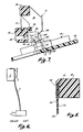
- a mounting arrangement is shown pictorially or schematically in Fig. 6, in which the pendulum is designated by the numeral 1, the support 2, and the clamp 3.
- the splayed upper portion of the pendulum is merely to help initially suspend the pendulum from corresponding support, and is not in and of itself suitable for actual operation in a vehicle since, in the first place, such a suspension would merely permit the pendulum to rock back and forth under the influence of braking inertia, and would not produce any flexure of the pendulum blade or any resilient damping effect, etc., and, in the second place, such a mounting would not secure the pendulum against vertical forces generated when the vehicle encountered road surface irregularities, etc.
- the present invention recognizes that the typical prior art pendulum mounting, such as that illustrated in Fig. 6, severely inhibits consistent and gradual pendulum flexure in response to inertial loading, since it forces the pendulum to act, in effect, as a multi-leaf spring having both of its ends rigidly secured together. In such a situation, the resulting spring action is irregular and erratic, for the reasons noted previously. Indeed, the pattern of flexure for such a pendulum is likely to be that indicated in Fig. 6, in which the pendulum blade 1 actually defines a somewhat S-shaped curve rather than the anticipated and desired smooth arcuate curve which would result from a single leaf or from multiple leaves which are not fixed to one another at both ends.
- the motion pattern characteristic of a pendulum which exhibits such flexure is complex and non-uniform; consequently, this erratic pattern will also be present in the analog output of any sensor used to monitor and represent the pendulum motion, as well as in the resultant actuation of the brake system so controlled, which will thus embody irregular application, chatter, and other undesirable attributes.
- the pendulum While the lower extremity of the pendulum used in accordance with the present invention continues to maintain the presence of a centred weight or mass which enhances pendulum flexure under the influence of braking inertia, the pendulum itself is mounted in an entirely different way at the top, providing for free longitudinal movement of the metal leaves relative to one another, under the influence of viscous damping provided by the interposed elastomeric adhesive layer which interconnects the two metal strips.
- the inertial sensing pendulum 10 in accordance with the present invention is comparatively short with respect to its width, particularly in relation to prior art structures (in which the "free" portion of which, between the mounting at the top and the weight block at the bottom, was of the order of about three times longer).
- the preferred length-width ratio for this "free" portion of the pendulum in accordance herewith is of the order of about 1:2, for the particular embodiment being described.
- Other important attributes of this form of pendulum are set forth in more detail hereinafter.
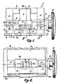
- the pendulum 10 is mounted on a pivotal or support assembly 12 comprising a pair of mutually-spaced upwardly-extending support arms 14 and 16 which carry a crossbeam 18 from which the pendulum 10 is suspended, preferably in a particular manner described more fully hereinafter.
- the mutually-spaced support arms 14 and 16 are also interconnected by a small-section blocking bar 20 which is disposed directly in alignment with a weighting block 22 secured at the bottom of the pendulum, so as to prevent undue excursion of the pendulum in that direction.
- the block 22 comprises a rectangular member mounted on the end of the pendulum 10 and having a transverse passage 24 in which a metal or other weight is secured.
- the weighting block 22 receives the bottom of the pendulum in a slot and is secured in place by adhesive or the like in a manner which provides a unified structure that captures the lower end of the pendulum and secures its different component layers with respect to one another.
- An alternative arrangement will be noted hereinafter.
- the mounting assembly 12 preferably comprises an integrally-moulded structure which includes not only the elements mentioned above (i.e., suspension arms 14 and 16, and crossarm 18) but, in addition, a support base portion 26 having mutually-spaced support arms 28 and 30, upon which the suspension arms 14 and 16 are mounted.
- the manner in which this is preferably accomplished is by moulding the entire assembly as an integral one-piece unit and providing a thin "living hinge" section 32, which allows for pivotal movement of the suspension arms with respect to their corresponding support arms, the extent of such movement being limited to a predetermined range by corresponding angularly-disposed shoulders 34, 36 and 38, 40, respectively.
- a suitable material for the integrally-moulded mounting assembly 12 is nylon, but other generally rigid polymers or the like may be equally suitable.
- the support base 26 is preferably formed so as to be directly mountable upon a printed circuit (i.e., "p.c.") board 42, such that the entire inertial sensor may be so mounted for rapid assembly procedures.
- a printed circuit i.e., "p.c.”
- pendulum attitude adjustment was provided by mounting the pendulum in a manner permitting relative angular motion of the entire pendulum support structure with respect to the instrument housing in which it was contained, as opposed to the more limited type of adjustment provided in accordance herewith, as just described.
- the present invention provides for mounting of the optical components (here designated by the numerals 44 and 46, and constituting an "optical pair," i.e., a light source such as a photodiode and a light detector such as a phototransistor) directly upon the pendulum mounting assembly support base 26, in a manner whereby the height of the light beam provided by the optical pair (here indicated by the circular passage 48) is readily aligned and located in its desired position with respect to the pendulum. That is, the electrical conductors 50 and 52 of the optical pair extend downwardly through appropriate passages in support base 26 and through the p.c. board 42, where they are accessible for connection to the other electrical components of the brake-actuation system.
- an optical pair i.e., a light source such as a photodiode and a light detector such as a phototransistor
- the optical pair is positioned and mounted by use of a support base 26 having a separately-formed, and separable, mounting block 26a (Figs. 1 and 2), which fits into a recess defined between leg portions 26b of the support base.
- This facilitates mounting of the optical pair 44, 46, since one need only place the mounting block 26a atop the circuit board in the desired position, separate and apart from the remainder of the mounting assembly 12, and insert the leads 50, 52 through the corresponding passages in the mounting block and the p.c. board, bending the protruding portions laterally as shown in Fig. 1 to hold the optical devices and mounting block in position on the circuit board and at the same time automatically set the desired location of the optical path 48. That is, the thickness of mounting block 26a may be made such that the optical pair is automatically indexed in position at a desired level above the top of the support base 26 when they are mounted in the manner just stated.
- the mounting assembly 12 is secured to the p.c. board 42 with leg portions 26b disposed on each side of mounting block 26a, as shown in Fig. 2.
- the attachment of support base 26 to circuit board 42 is accomplished by one or more pairs of spaced posts 54 which are moulded integrally as part of the pendulum mounting assembly 12 and are of a stiffly flexible nature, the preferred assembly procedure being to place the integral mounting assembly 12 upon the p.c. board 42 in the position just noted, and push the posts 54 through corresponding passages provided in the p.c. board for this purpose.
- the pendulum 10 is secured to the mounting assembly 12 in a novel and distinctive manner. More particularly, the entire securement for the pendulum is preferably accomplished by adhesive attachment of one of its metal leaves to the face of the crossbeam 18 in the desired location (which may be denoted by an integrally-moulded recess in the face of crossbeam 18, or by a slightly protruding peripheral frame 68 [Figs. 1 and 2] having a size substantially corresponding to that of the end of pendulum 10). In this manner, only one of the metal strips comprising the laminate pendulum structure 10 is actually secured to the mounting assembly 12, i.e., the metal strip 10c (Fig. 5) disposed closest to crossbeam 18.
- a preferred adhesive 70 for use in mounting the pendulum 10 in this manner is the resin adhesive sold by Morgan Adhesive Company and identified as "Dymax 029," using activator 535; however, many commercial adhesives would no doubt be satisfactory for such an application.
- a flag or shutter 56 carried with the weight block 22 moves correspondingly to the left, thereby progressively opening a light passage between the optical pair 44, 46, along path 48.
- the pendulum 10 flexes laterally in a smooth arcuate bending mode, requiring that the metal strip 10a disposed on the left as seen in Fig. 5 begins to describe a curve of shorter radius than the metal strip 10c disposed on the right side of the pendulum as seen in that Figure. Consequently, the metal strip 10a located on the left must not be precluded from moving longitudinally upwardly with respect to the other strip 10c, as seen in such Figure, and this capability is provided by the novel mounting in accordance with the present invention.
- suitable clearance may need to be provided between the upper edge of the metal strip 10a and the overhang of the block 18 to facilitate this or the overhang may be omitted.
- the left-hand strip of metal in the pendulum would have to exhibit compound flexure, potentially including even certain bending in the nature of elastic buckling, in responding to the inertial forces applied (e.g., as illustrated at least partially in Fig. 6).
- the pendulum mounting provided by the present invention facilitates the free flexure of the two metal strips in the pendulum, together with enabling the consistent and unrestricted viscous damping characteristic provided by the elastomeric connecting layer, will be appreciated by those skilled in the art.
- the bottom extremity of the pendulum may also be secured in this general manner, i.e., by securing only one of the metal leaves to the weight block 22, leaving the other free to move longitudinally with respect thereto.
- the top end of the pendulum may, if desired, be secured in a different manner, even by clamping, but it will also be understood that the preferred adhesive mounting structure for the top of the pendulum disclosed above is a significant improvement, in and of itself, from the standpoint of effective, efficient, and reliable manufacturing techniques, the upper portion of the mounting assembly (suspension arms 14 and 16, crossbeam 18, etc.) already being secured to the lower portion (including the support base 26 and support arms 28, 30, etc.) upon initial forming of the component parts.
- the means for rotating the pendulum suspension arms 14 and 16 with respect to the support base, etc., in order to adjust the attitude (e.g., verticality) of the pendulum in a given setting is preferably comprised of an integrally-moulded stub shaft and eccentric assembly 60 (Figs. 1 and 2), which includes an adjustment shaft 62 which is secured to suspension arm 16 through an eccentric connecting link 64 and a stub shaft 66, the axis of shaft 62 being centred upon the hinge pivot axis 48a.
- An operating knob 68a is also preferably moulded integrally with the adjustment shaft 62, to provide a convenient means for the vehicle operator to effect rotational adjustment as required, shaft 62 extending outward through the case wall of the instrument by means of an appropriate aperture (not specifically shown).
- shaft 62 is encircled by an appropriate split grommet (not shown) which interposes frictional forces between the shaft and the housing wall through which it extends, such that the entire adjustment assembly 60, together with support arms 14 and 16 and crossbeam 18, will automatically be held, by such frictional forces, in desired positions of adjustment once rotational correction has been made.
- corrective pendulum attitude adjustment comprises rotation about the optical axis of the detection pair 44, 46, so that the verticality of the pendulum may be corrected under any anticipated mounting position without changing the relative position of the shutter flag 56 with respect to such optical axis and thereby changing the inertial sensitivity of the device.
- the support base 26 in particular, the mounting block portion 26a thereof
- forms a recess 72 Figs. 1 and 2 into which the projecting end of pendulum flag 56 may move upon corresponding rotational movement of adjustment knob 66.
- a preferred optical pair 44, 46 for use in connection with the invention is that manufactured by Motorola and identified as MLED 71 (infrared L.E.D.) and MRD 701 (phototransistor), or equivalent, which provides a highly restricted (small diameter) optical beam for interaction with the pendulum shutter 56.
- MLED 71 infrared L.E.D.
- MRD 701 phototransistor
- detection beam which has a width of the order of only about 0.5 mm (twenty thousandths of an inch), and this makes possible the use of the relatively short, stiff (minimum deflection) pendulum, as noted above.
- inertial sensing stability is so improved that the braking control unit may entirely omit the customary interconnection with the vehicle brake light circuit, heretofore considered an indispensable part of electric brake control apparatus whether inertially-responsive or otherwise. Nonetheless, there is no need to fear the presence of erratic or inadvertent actuation resulting from rough driving surfaces, etc., due to the extreme stability provided by the present improvements.
- braking actuation of the towed vehicle occurs smoothly and effectively, and only as a result of intentional or intended actuation, and is of substantially better quality and resolution than that characteristically provided by prior art devices.
Landscapes
- Physics & Mathematics (AREA)
- General Physics & Mathematics (AREA)
- Vehicle Body Suspensions (AREA)
- Switches Operated By Changes In Physical Conditions (AREA)
- Force Measurement Appropriate To Specific Purposes (AREA)
Applications Claiming Priority (2)
| Application Number | Priority Date | Filing Date | Title |
|---|---|---|---|
| US07/390,280 US5058960A (en) | 1989-08-07 | 1989-08-07 | Pendulum-type accellerometer for electrically-actuated braking systems |
| US390280 | 1989-08-07 |
Publications (3)
| Publication Number | Publication Date |
|---|---|
| EP0414413A2 true EP0414413A2 (de) | 1991-02-27 |
| EP0414413A3 EP0414413A3 (en) | 1991-03-06 |
| EP0414413B1 EP0414413B1 (de) | 1994-03-16 |
Family
ID=23541835
Family Applications (1)
| Application Number | Title | Priority Date | Filing Date |
|---|---|---|---|
| EP90308702A Expired - Lifetime EP0414413B1 (de) | 1989-08-07 | 1990-08-07 | Pendelbeschleunigungsmesser für elektrisch betätigte Bremssysteme |
Country Status (5)
| Country | Link |
|---|---|
| US (1) | US5058960A (de) |
| EP (1) | EP0414413B1 (de) |
| AU (2) | AU629634B2 (de) |
| CA (1) | CA2014084C (de) |
| DE (1) | DE69007376T2 (de) |
Cited By (1)
| Publication number | Priority date | Publication date | Assignee | Title |
|---|---|---|---|---|
| EP0707213A3 (de) * | 1994-10-11 | 1999-12-08 | Fujikura Ltd. | Servo-Beschleunigungsmessaufnehmer sowie Verfahren zur Berechnung der Beschleunigung eines Fahrzeuges auf einer geneigten Ebene |
Families Citing this family (20)
| Publication number | Priority date | Publication date | Assignee | Title |
|---|---|---|---|---|
| US5442332A (en) * | 1993-02-19 | 1995-08-15 | Hughes; Michael T. | Vehicle interface system and method |
| US5333948A (en) * | 1993-06-22 | 1994-08-02 | Tekonsha Engineering Company | Multiple-gain electronic brake actuator with trigger point inertial sensor |
| JPH08297139A (ja) * | 1995-04-26 | 1996-11-12 | Mitsubishi Electric Corp | 半導体加速度センサ |
| US5700068A (en) * | 1995-10-16 | 1997-12-23 | Tekonsha Engineering Company | Positioning apparatus for inertial sensors |
| US6068352A (en) * | 1996-08-20 | 2000-05-30 | Tekonsha Engineering Company | Microprocessor-based control for trailer brakes |
| CA2303060A1 (en) | 1999-04-14 | 2000-10-14 | United States Gear Corporation | Towed vehicle brake controller |
| US6282480B1 (en) | 1999-10-29 | 2001-08-28 | Dennis M. Morse | Electronic brake controller and display |
| US6367588B1 (en) * | 2000-04-20 | 2002-04-09 | Hayes Lemmerz International, Inc. | Deceleration sensor for an electric brake controller |
| US6445993B1 (en) | 2000-11-22 | 2002-09-03 | Larry Eccleston | Brake control unit |
| US8746812B2 (en) * | 2004-10-08 | 2014-06-10 | Marcia Albright | Brake control unit |
| US8789896B2 (en) * | 2004-10-08 | 2014-07-29 | Cequent Electrical Products | Brake control unit |
| USD527710S1 (en) | 2004-10-27 | 2006-09-05 | Cequent Electric Products | Vehicle brake controller |
| US8430458B2 (en) * | 2005-11-23 | 2013-04-30 | Hopkins Manufacturing Corp. | Towed vehicle braking apparatus |
| US20080296968A1 (en) * | 2007-05-30 | 2008-12-04 | Hayes Brake Controller Company, Llc | Electric trailer brake controller with an adjustable accelerometer mounting |
| USD598395S1 (en) | 2007-11-26 | 2009-08-18 | Cequent Electrical Products Inc. | Power control unit for trailer mounted brake controller |
| USD584695S1 (en) | 2007-11-26 | 2009-01-13 | Cequent Electrical Products, Inc. | Hand control unit for trailer mounted brake controller |
| US20110087413A1 (en) * | 2009-10-13 | 2011-04-14 | D-Brake, Llc | Tow brake |
| US10946841B2 (en) | 2016-09-16 | 2021-03-16 | Horizon Global Americas Inc. | Driver and diagnostic system for a brake controller |
| AU2017326536A1 (en) | 2016-09-16 | 2019-05-02 | Horizon Global Americas Inc. | Combination of trailer braking and lighting functions |
| US10363910B2 (en) | 2016-12-07 | 2019-07-30 | Horizon Global Americas Inc. | Automated gain and boost for a brake controller |
Family Cites Families (13)
| Publication number | Priority date | Publication date | Assignee | Title |
|---|---|---|---|---|
| US3738710A (en) * | 1971-02-25 | 1973-06-12 | Jordan Res Corp | Electronic trailer brake actuator |
| US3953084A (en) * | 1973-08-02 | 1976-04-27 | Tekonsha Engineering Co. | Towed vehicle electric brake control |
| US3909075A (en) * | 1973-08-02 | 1975-09-30 | Tekonsha Engineering Co | Towed vehicle electric brake control system |
| US3897979A (en) * | 1974-07-15 | 1975-08-05 | Vantronics Inc | Trailer brake control system |
| US3981544A (en) * | 1974-12-09 | 1976-09-21 | Tekonsha Engineering Company | Brake controller and short circuit probe disconnect |
| US3967863A (en) * | 1974-12-09 | 1976-07-06 | Tekonsha Engineering Company | Brake controller and short circuit probe disconnect |
| US4030756A (en) * | 1975-12-29 | 1977-06-21 | Tekonsha Engineering Company | Magnetic dampened inertial sensor for brake and sway controls |
| SE411687B (sv) * | 1978-05-31 | 1980-01-28 | Aga Ab | Accelerometer for metning av vinkellege i vertikalled |
| GB2146697B (en) * | 1983-09-17 | 1986-11-05 | Stc Plc | Flexible hinge device |
| SE441127B (sv) * | 1984-01-25 | 1985-09-09 | Asea Ab | Accelerometer |
| US4726627A (en) * | 1984-10-22 | 1988-02-23 | Kelsey-Hayes Co. | Deceleration sensor for an electric brake controller |
| US4638669A (en) * | 1985-05-07 | 1987-01-27 | Massachusetts Institute Of Technology | Quantum tunneling cantilever accelerometer |
| US4849655A (en) * | 1985-07-04 | 1989-07-18 | Hayman-Reese Party, Limited | Accelerometer or decelerometer for vehicle brake control system |
-
1989
- 1989-08-07 US US07/390,280 patent/US5058960A/en not_active Expired - Lifetime
-
1990
- 1990-04-06 CA CA002014084A patent/CA2014084C/en not_active Expired - Fee Related
- 1990-05-11 AU AU54988/90A patent/AU629634B2/en not_active Ceased
- 1990-08-07 EP EP90308702A patent/EP0414413B1/de not_active Expired - Lifetime
- 1990-08-07 DE DE69007376T patent/DE69007376T2/de not_active Expired - Fee Related
-
1992
- 1992-11-23 AU AU28567/92A patent/AU655515B2/en not_active Ceased
Cited By (1)
| Publication number | Priority date | Publication date | Assignee | Title |
|---|---|---|---|---|
| EP0707213A3 (de) * | 1994-10-11 | 1999-12-08 | Fujikura Ltd. | Servo-Beschleunigungsmessaufnehmer sowie Verfahren zur Berechnung der Beschleunigung eines Fahrzeuges auf einer geneigten Ebene |
Also Published As
| Publication number | Publication date |
|---|---|
| CA2014084C (en) | 1995-10-24 |
| DE69007376T2 (de) | 1994-06-23 |
| AU5498890A (en) | 1991-02-07 |
| DE69007376D1 (de) | 1994-04-21 |
| AU629634B2 (en) | 1992-10-08 |
| AU655515B2 (en) | 1994-12-22 |
| CA2014084A1 (en) | 1991-02-07 |
| US5058960A (en) | 1991-10-22 |
| AU2856792A (en) | 1993-01-28 |
| EP0414413A3 (en) | 1991-03-06 |
| EP0414413B1 (de) | 1994-03-16 |
Similar Documents
| Publication | Publication Date | Title |
|---|---|---|
| EP0414413B1 (de) | Pendelbeschleunigungsmesser für elektrisch betätigte Bremssysteme | |
| JP4091202B2 (ja) | 測定装置用の懸架装置 | |
| US5277064A (en) | Thick film accelerometer | |
| EP0137283B1 (de) | Optischer Kopf | |
| US5027657A (en) | Acceleration sensor with cantilevered bending beam | |
| US5001583A (en) | Flexible polymeric resinous magnetic head supporting device | |
| US5006946A (en) | Flexible polymeric resinous magnetic head supporting device | |
| US6469415B2 (en) | Balanced microdevice and rotary electrostatic microactuator use therewith | |
| US5072433A (en) | Objective lens mount utilizing leaf springs | |
| JP4028785B2 (ja) | 荷重検出ユニットおよびこれを利用した電子秤 | |
| US5144607A (en) | Objective lens driving device | |
| CA2186902C (en) | Positioning apparatus for inertial sensors | |
| US5231879A (en) | Semiconductor acceleration detecting apparatus | |
| JPS62189679A (ja) | リミツト・ストツプ装置 | |
| CA1191712A (en) | Accelerometer pendulum support assembly | |
| KR930009682B1 (ko) | 광디스크 구동장치의 광픽업장치 | |
| US5542296A (en) | Compact capacitive acceleration sensor | |
| US4938065A (en) | Acceleration detecting device | |
| US6903486B2 (en) | Balanced microdevice | |
| JPS6218980B2 (de) | ||
| US6377407B1 (en) | Optical scanning device having an improved response characteristic | |
| US7558168B2 (en) | Optical pickup device with a tilt adjusting actuator | |
| US7468826B2 (en) | Silicon mirrors having reduced hinge stress from temperature variations | |
| US4188829A (en) | Flexure pivot accelerometer | |
| CA2569295C (en) | Seismic sensor |
Legal Events
| Date | Code | Title | Description |
|---|---|---|---|
| PUAI | Public reference made under article 153(3) epc to a published international application that has entered the european phase |
Free format text: ORIGINAL CODE: 0009012 |
|
| PUAL | Search report despatched |
Free format text: ORIGINAL CODE: 0009013 |
|
| AK | Designated contracting states |
Kind code of ref document: A2 Designated state(s): BE DE GB |
|
| AK | Designated contracting states |
Kind code of ref document: A3 Designated state(s): BE DE GB |
|
| 17P | Request for examination filed |
Effective date: 19910816 |
|
| 17Q | First examination report despatched |
Effective date: 19920903 |
|
| GRAA | (expected) grant |
Free format text: ORIGINAL CODE: 0009210 |
|
| AK | Designated contracting states |
Kind code of ref document: B1 Designated state(s): BE DE GB |
|
| REF | Corresponds to: |
Ref document number: 69007376 Country of ref document: DE Date of ref document: 19940421 |
|
| PLBE | No opposition filed within time limit |
Free format text: ORIGINAL CODE: 0009261 |
|
| STAA | Information on the status of an ep patent application or granted ep patent |
Free format text: STATUS: NO OPPOSITION FILED WITHIN TIME LIMIT |
|
| 26N | No opposition filed | ||
| REG | Reference to a national code |
Ref country code: GB Ref legal event code: IF02 |
|
| PGFP | Annual fee paid to national office [announced via postgrant information from national office to epo] |
Ref country code: GB Payment date: 20050707 Year of fee payment: 16 |
|
| PGFP | Annual fee paid to national office [announced via postgrant information from national office to epo] |
Ref country code: BE Payment date: 20050826 Year of fee payment: 16 |
|
| PGFP | Annual fee paid to national office [announced via postgrant information from national office to epo] |
Ref country code: DE Payment date: 20050831 Year of fee payment: 16 |
|
| PG25 | Lapsed in a contracting state [announced via postgrant information from national office to epo] |
Ref country code: BE Free format text: LAPSE BECAUSE OF NON-PAYMENT OF DUE FEES Effective date: 20060831 |
|
| PG25 | Lapsed in a contracting state [announced via postgrant information from national office to epo] |
Ref country code: DE Free format text: LAPSE BECAUSE OF NON-PAYMENT OF DUE FEES Effective date: 20070301 |
|
| GBPC | Gb: european patent ceased through non-payment of renewal fee |
Effective date: 20060807 |
|
| PG25 | Lapsed in a contracting state [announced via postgrant information from national office to epo] |
Ref country code: GB Free format text: LAPSE BECAUSE OF NON-PAYMENT OF DUE FEES Effective date: 20060807 |
|
| BERE | Be: lapsed |
Owner name: *TEKONSHA ENGINEERING CY Effective date: 20060831 |