EP0414426B1 - Supraleitender Analog-zu-Digital-Konverter mit einem geerdeten Vier-Übergang-Squid-Zweirichtungszähler - Google Patents
Supraleitender Analog-zu-Digital-Konverter mit einem geerdeten Vier-Übergang-Squid-Zweirichtungszähler Download PDFInfo
- Publication number
- EP0414426B1 EP0414426B1 EP90308873A EP90308873A EP0414426B1 EP 0414426 B1 EP0414426 B1 EP 0414426B1 EP 90308873 A EP90308873 A EP 90308873A EP 90308873 A EP90308873 A EP 90308873A EP 0414426 B1 EP0414426 B1 EP 0414426B1
- Authority
- EP
- European Patent Office
- Prior art keywords
- junction
- count
- flop
- flip
- squid
- Prior art date
- Legal status (The legal status is an assumption and is not a legal conclusion. Google has not performed a legal analysis and makes no representation as to the accuracy of the status listed.)
- Expired - Lifetime
Links
- 230000002457 bidirectional effect Effects 0.000 title claims description 23
- 241000238366 Cephalopoda Species 0.000 title description 102
- 230000004907 flux Effects 0.000 claims description 34
- 238000007667 floating Methods 0.000 claims description 14
- 230000001965 increasing effect Effects 0.000 claims description 12
- 230000003247 decreasing effect Effects 0.000 claims description 11
- 230000001939 inductive effect Effects 0.000 claims description 2
- 238000010586 diagram Methods 0.000 description 12
- 238000005070 sampling Methods 0.000 description 8
- 238000006243 chemical reaction Methods 0.000 description 6
- 238000000034 method Methods 0.000 description 6
- 230000008859 change Effects 0.000 description 5
- 230000007704 transition Effects 0.000 description 5
- 230000000644 propagated effect Effects 0.000 description 4
- 230000035945 sensitivity Effects 0.000 description 4
- 238000004804 winding Methods 0.000 description 4
- 230000000737 periodic effect Effects 0.000 description 3
- 230000007423 decrease Effects 0.000 description 2
- 230000001419 dependent effect Effects 0.000 description 2
- 230000000694 effects Effects 0.000 description 2
- 230000008569 process Effects 0.000 description 2
- 238000006842 Henry reaction Methods 0.000 description 1
- 238000005516 engineering process Methods 0.000 description 1
- 239000000463 material Substances 0.000 description 1
- 230000004044 response Effects 0.000 description 1
- 239000002887 superconductor Substances 0.000 description 1
Images


Classifications
-
- H—ELECTRICITY
- H03—ELECTRONIC CIRCUITRY
- H03M—CODING; DECODING; CODE CONVERSION IN GENERAL
- H03M1/00—Analogue/digital conversion; Digital/analogue conversion
- H03M1/12—Analogue/digital converters
- H03M1/48—Servo-type converters
Definitions
- This invention relates generally to analog-to-digital converters and, more particularly, to high-speed, high-resolution analog-to-digital converters employing superconducting Josephson junctions.
- High-performance analog-to-digital (A/D) converters are required in a variety of commercial and military electronic devices. Two of the more important measures of an A/D converter's performance are its speed, as measured by the number of samples converted per second, and resolution, as measured by the smallest increment of change that can be detected in an analog signal.
- Superconducting technology is particularly well suited to performing high-speed, high-resolution A/D conversion because Josephson junctions, which are the basic switching elements utilized in superconducting electronic devices, possess a unique combination of speed, sensitivity, and periodic response characteristics.
- the Josephson junction is a simple bistable switching device having a very thin insulating layer sandwiched between two superconducting electrodes.
- the device When current supplied to the Josephson junction is increased above the critical current of the junction, the device is switched from a superconducting zero-voltage state to a resistive voltage state.
- the resistive voltage state in which the voltage drop across the device is equal to the energy gap of the superconductor material, is switched off by reducing the current supplied to the junction to about zero. Because this switching operation can occur in as little as a few picoseconds, the Josephson junction is truly a high speed switching device.
- a superconducting A/D converter one or more of the Josephson junctions are combined with one or more inductive loads to form a logic circuit called a SQUID, or Superconducting Quantum Interference Device.
- the characteristics of the SQUID that provide the basis for superconducting A/D conversion can best be explained with reference to a single-junction SQUID.
- the single-junction SQUID which is simply a Josephson junction connected across an inductance to form a superconducting loop, exhibits a periodic and multivalued relationship between the current injected into the inductance and the magnetic flux in the loop.
- the magnetic flux in the loop increases by a small quantum whenever the current increases by a small and precisely repeatable increment. This quantum of flux gives rise to a small but measurable voltage pulse across the junction.
- the magnetic flux in the loop decreases by the small quantum, and a corresponding voltage pulse of the opposite polarity is produced across the junction.
- the analog signal is introduced into the SQUID as a varying current. Each time the current increases or decreases by a predetermined amount, a measurable voltage pulse is generated across the junction. In this manner, the SQUID functions as a quantizer, with the resultant pulses being detected and counted in one or more binary counters.
- the principle advantages of this superconducting counting A/D converter are its near perfect linearity and its high sensitivity and speed.
- the current increment or decrement which determines the resolution of the device, can be made extremely small. This is because a single flux quantum is only 2.07 x 10 ⁇ 15 weber and the current increment or decrement is the flux quantum divided by the value of the inductance (measured in henries).
- U.S. Patent No. 4,646,060 to Phillips et al. discloses a superconducting counting A/D converter having a double-junction SQUID quantizer and a bidirectional binary counter comprised of n stages of double-junction SQUID flip-flops, where n is the number of bits of accuracy of the counter.
- the quantizer generates up-count and down-count voltage pulses of the same polarity on two different output lines, rather than voltage pulses of the opposite polarity on the same output line, as in the single-junction SQUID.
- the bidirectional binary counter algebraically counts the voltage pulses, increasing the binary count when up-count pulses are received and decreasing the binary count when down-count pulses are received.
- Superconducting logic circuitry which includes numerous AND and OR gates, provides the carry and borrow functions of the counter.
- the Phillips et al. A/D converter has certain advantages, it also has several disadvantages.
- One disadvantage is that the additional logic circuitry reduces the speed and increases the device count of the A/D converter.
- An increased device count reduces the reliability of the A/D converter and also increases its cost. Accordingly, there has been a need for a superconducting analog-to-digital converter that does not require this additional logic circuitry.
- the present invention fulfills this need.
- the present invention resides in a high-speed, high-resolution superconducting counting A/D converter providing greatly increased conversion speeds with a low device count.
- the superconducting counting A/D converter includes a double-junction SQUID quantizer and a bidirectional binary counter having n stages of four-junction SQUID flip-flops that may be either floating or grounded, where n is the number of bits of accuracy of the counter.
- the quantizer continuously tracks an analog signal, generating up-count and down-count voltage pulses of the same polarity on two different output lines for increasing and decreasing values of the analog current, respectively.
- the bidirectional binary counter algebraically counts the voltage pulses, increasing the binary count when up-count pulses are received and decreasing the binary count when down-count pulses are received.
- the quantizer includes two Josephson junctions and a center-tapped inductance connected together to form a superconducting loop.
- a constant gate current is injected into the center-tap terminal of the inductance, while the analog signal is transformer-coupled through a winding to the inductance.
- the bidirectional binary counter includes n stages of the floating four-junction SQUID flip-flops connected together in a cascade arrangement from the least significant bit (LSB) to the most significant bit (MSB).
- Each floating four-junction SQUID flip-flop includes four Josephson junctions and two center-tapped inductances connected together to form a superconducting loop.
- the four-junction SQUID flip-flop is a bistable logic circuit in which the direction of the circulating current determines the state of the circuit.
- a "O" bit is represented by a counterclockwise circulating supercurrent and a "I” bit is represented by a clockwise circulating supercurrent
- an up-count or down-count pulse is applied to the SQUID flip-flop, the current through one of the Josephson junctions is raised momentarily above the critical current of the junction. This causes the Josephson junction to generate a voltage pulse, thereby reversing the direction of the circulating current. Subsequent pulses applied to the SQUID flip-flop cause the flip-flop to toggle or reverse state.
- an up-count pulse will ripple from flip-flop to flip-flop, changing the binary state of each stage and generating a carry pulse if the initial state of the stage is a "1.”
- a down-count pulse will also ripple from flip-flop to flip-flop, changing the binary state of each stage and generating a borrow pulse if the initial state of the stage is a "0.”
- the quantizer is a single-junction SQUID quantizer.
- the single-junction quantizer generates up-count and down-count voltage pulses of the opposite polarity on a single output line for positive and negative values of an analog voltage, respectively.
- the quantizer digitizes an analog voltage, rather than an analog current, using the alternating current effect of Josephson junctions. When a voltage is applied to a Josephson junction, an alternating current is generated across the junction. Because the frequency of the current is dependent on the magnitude of the voltage, the average voltage during the sampling interval can be digitized by counting the frequency of the alternating current over that time interval.
- the SQUID flip-flops are grounded three-junction SQUID flip-flops.
- Each grounded three-junction SQUID flip-flop includes two inductances and three Josephson junctions. Two of the Josephson junctions are similar to the two Josephson junctions in the four-junction SQUID flip-flop and the third Josephson junction replaces the other two Josephson junctions by pulsing either positively or negatively.
- the quantizer and the LSB four-junction SQUID flip-flop are combined to provide a four-junction SQUID quantizer having an additional bit of sensitivity.
- the high-speed, high-resolution superconducting counting A/D converter of the present invention may be used with means for reading the contents of the counter at the end of each sampling interval.
- One technique for reading the contents of the counter is to utilize a toggling quantizer and two bidirectional binary counters.
- the quantizer toggles between the two counters at the end of each sampling interval so that one counter can be read while the other counter is counting, and vice versa.
- An adder combines the outputs of the two counters.
- Another technique for reading the contents of the binary counter is to utilize a variable-hysteresis quantizer.
- the variable-hysteresis quantizer inhibits the generation of voltage pulses during the read period, allowing the counter to be read without missing any changes in the analog signal.
- the A/D converter of the present invention has many advantages, including very fast A/D conversion speeds and a low device count. These advantages result from the ability of the four-junction SQUID flip-flops to control both the binary states of the stages of the counter and the bidirectional transitions and propagations of the counter.
- the gates that would normally process this logic cannot operate at the required speeds. Therefore, eliminating the logic gates results in an extremely fast counter which can count up or down at speeds greater than 1 count every 10 picoseconds, or a counting rate of 100 GHz. Eliminating the logic gates also reduces the device count, which greatly enhances reliability and reduces power consumption and cost.
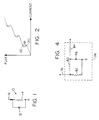
- Figure 1 illustrates a single-junction SQUID 10 in which a Josephson junction 12 is connected across an inductance 14 to form a superconducting loop.
- One terminal of the inductance 14 is connected to a current source, indicated at 16, and the other terminal is connected to ground.
- Figure 2 is a simplified representation of the relationship between the injected current and the magnetic flux in the loop.
- the magnetic flux increases, until a multi-valued region of the curve is reached, as indicated at 18.
- a current-reversal point 20 is reached, a further increase in the current causes the magnetic flux to jump to a higher level of the multi-valued region, as indicated at 22. This sudden flux increment results in a small but measurable voltage pulse across the Josephson junction 12.
- the curve of Figure 2 is perfectly periodic in that the current increments between successive peaks in the curve are uniform, as are the magnetic flux increments that are generated as a result of the current increments.
- the magnetic flux in the loop is reduced, and corresponding voltage pulses of the opposite polarity are generated across the Josephson junction 12.
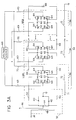
- Figures 3A and 3B illustrate a high-speed, high resolution superconducting counting A/D converter according to the present invention with Figure 3A representing the bidirectional counter 34 having n stages of floating four-junction SQUID flip-flops 36 and in Figure 3B the four-junction SQUID flip-flops 236 are grounded.
- Figure 3A illustrates a high-speed, high-resolution superconducting counting A/D converter according to the present invention.
- the superconducting counting A/D converter includes a double-junction SQUID quantizer 32 and a bidirectional binary counter 34 having n stages of floating four-junction SQUID flip-flops 36, where n is the number of bits of accuracy of the counter.
- the A/D converter includes a double junction SQUID quantizer 232 and a bidirectional binary counter 234 having n states of grounded four-junction SQUID flip-flops 236..
- the quantizer 232 continuously tracks an analog signal, on line 238, generating up-count and down-count voltage pulses of the same polarity on two different output lines for increasing and decreasing values of the analog current, respectively.
- the bidirectional binary counter 34 (Fig 3A) and 234 (Fig. 3B) algebraically counts the voltage pulses, increasing the binary count when up-count pulses are received and decreasing the binary count when down-count pulses are received.
- the quantizer 32 includes two Josephson junctions 40, 42 and a center-tapped inductance 44 connected together to form a superconducting loop.
- One terminal of each of the Josephson junctions 40, 42 is connected to a different end terminal of the inductance 44 and the other terminal of each of the Josephson junctions 40, 42 is connected to ground.
- a constant gate current, on line 46 is injected into the center-tap terminal of the inductance 44.
- the analog signal on line 38 is transformer-coupled through a winding 48 to the inductance 44. Alternatively, the analog signal on line 38 may be directly coupled into the inductance 44.
- up-count and down-count signals are output to the binary counter 34 from the terminals between the inductance 44 and the Josephson junctions 40, 42, respectively, and are each applied to the counter through a resistor 50.
- the bidirectional binary counter 34 includes n stages of the floating four-junction SQUID flip-flops 36 connected together in a cascade arrangement from the least significant bit (LSB) to the most significant bit (MSB).
- Each floating four-junction SQUID flip-flop 36 includes four Josephson junctions 52, 54, 56, 58 and two center-tapped inductances 60, 62 connected together to form a superconducting loop.
- One terminal of each of the Josephson junctions 52, 54 is connected to a different end terminal of inductance 60 and one terminal of each of the Josephson junctions 56, 58 is connected to a different end terminal of inductance 62.
- Josephson junctions 52, 56 are connected together and the other terminals 5 of Josephson junctions 54, 58 are connected together.
- Each of the Josephson junctions 52, 54, 56, 58 also has a shunt resistor 64 connected across its terminals.
- the center-tap terminal of inductance 60 receives the carry signal from the preceding four-junction SQUID flip-flop 36 and 36′, or the up-count signal from the quantizer 32 if the four-junction SQUID flip-flop is the LSB flip-flop, and the center-tap terminal of inductance 62 receives the down-count or borrow signal.
- the carry and borrow signals are output to the succeeding four-junction SQUID flip-flop 36 from the terminal between Josephson junction 54 and inductance 60 and from the terminal between Josephson junction. 58 and inductance 62, respectively, and are each applied to the succeeding SQUID flip-flop through a resistor 66.
- a constant gate current is supplied to each four-junction SQUID flip-flop 36 by applying an ungrounded constant voltage source 68 ungrounded to resistors 69 ( Figure 3A).
- the constant gate current flows through each SQUID flip-flop from the terminal between Josephson junctions 52, 56 to the terminal between Josephson junctions 54, 58, where it is returned to the constant voltage source 68 through resistors 70. Because the voltage source 68 and the four-junction SQUID flip-flops 36 are ungrounded, the SQUID flip-flops operate in a floating mode. This allows all four Josephson junctions to be identical, providing a symmetrical SQUID flip-flop.
- a flux bias of F O /2 is generated in each SQUID flip-flop by a flux bias line 71 and inductances 72.
- the flux bias can be applied to the SQUID flip-flops by individual flux bias lines rather than by the single flux bias line 71.
- the flux bias induces a flux bias current in each SQUID flip-flop.
- the Josephson junctions 52, 54, 56, 58 are resistively shunted so that the SQUID flip-flops 36 operate in a nonlatching mode, which allows the SQUID flip-flops to operate at much faster speeds than when operated in a latching mode.
- Each four-junction SQUID flip-flop 36 (Fig. 3A) is a bistable logic circuit in which the direction of the circulating current determines the state of the circuit.
- a "O" bit is represented by a counterclockwise circulating supercurrent and a "l" bit is represented by a clockwise circulating supercurrent.
- an up-count or carry signal will ripple from flip-flop to flip-flop, changing the binary state of each stage and generating a further carry signal if the initial state of the stage is a "1.”
- a down-count or borrow signal will also ripple from flip-flop to flip-flop, changing the binary state of each stage and generating a further borrow signal if the initial state of the stage is a "0.”
- Josephson junction 54 When a SQUID flip-flop is indicating a "l", an 5 up-count or carry signal causes Josephson junction 54, to pulse and output a carry signal to the suceeding SQUID flip-flop, while a down-count or borrow signal causes Josephson junction 52 to pulse.
- Josephson junction 54 are the add-with-carry junction
- Josephson junction 56 are the add-without-carry junction
- Josephson junction 58 are the subtract-with borrow junction
- Josephson junction 52 are the subtract-without-borrow junction.
- a down-count or borrow signal supplies current to the loop which combines positively with the current through Josephson junction 58 and negatively with the current through Josephson junction 56. Therefore, the current through Josephson junction 58 will exceed its critical current, causing the junction to generate a voltage pulse.
- the circulation state of the SQUID flip-flop will change to a clockwise direction, and a borrow signal will be propagated to the next bit.
- the flux bias current and the gate current combine positively in Josephson junctions 52, 54 and negatively in Josephson junctions 56, 58. Accordingly, Josephson junctions 52, and 54 support relatively large current flows which will allow them to pulse due to a carry or borrow signal.
- An up-count or carry signal supplies current to the loop which combines positively with the current through Josephson junction 54 and negatively with the current through Josephson junction 52. Therefore, the current through Josephson junction 54 will exceed its critical current, causing the junction to generate a voltage pulse.
- the circulation state of the SQUID flip-flop will change to a counterclockwise direction, indicating a "0,” and a carry signal will be propagated to the next bit.
- a down-count or borrow signal supplies current to the loop which combines positively with the current through Josephson junction 52 and negatively with the current through Josephson junction 54. Therefore, the current through Josephson junction 52 will exceed its critical current, causing the junction to generate a voltage pulse.
- the circulation state of the SQUID flip-flop will change to a counterclockwise direction, and no carry or borrow signal will be propagated to the next bit.
- a flux bias of F O /2 is generated in each SQUID flip-flop by individual flux bias lines 270 and inductances 272.
- the flux bias can be applied to the SQUID flip-flops by a single flux bias line rather than by individual flux bias lines.
- the flux bias induces a flux bias current in each SQUID flip-flop.
- the Josephson junctions 252, 254, 256, 258 are resistively shunted so that the SQUID flip-flops 236 operate in a nonlatching mode, which allows the SQUID flip-flops to operate at much faster speeds than when operated in a latching mode.
- Each four-junction SQUID flip-flop 236 is a bistable logic circuit which operates in the same manner as described in connection with Figure 3A.
- the four possible transitions for each of the SQUID flip-flops 236, from a "0" up to a "1", from a “0” down to a “1”, from a "1” up to a “0”, and from a "1” down to a “0” function the same as the flip-flops 36 in Figure 3A.
- the quantizer is a single-junction SQUID quantizer 74, as illustrated in 35 Figure 4.
- the single-junction quantizer 74 generates up-count and down-count voltage pulses of the opposite polarity on a single output line for positive and negative values of an analog voltage, on line 76.
- the single output line of the quantizer 74 is applied to the center-tap terminal of inductance 60, while the center-tap terminal of inductance 62 is grounded.
- the single-junction quantizer 74 includes a Josephson junction 78, an inductance 80 and a resistor 82 connected together to form a superconducting loop.
- One terminal of the inductance 80 is connected to a terminal of the Josephson junction 78
- the other terminal of the inductance 80 is connected to a terminal of the resistor 82
- the other terminal of the resistor 82 is connected to the other terminal of the Josephson junction 78.
- the terminal between the Josephson junction 78 and the resistor 82 is grounded and the terminal between the inductance 80 and the resistor 82 receives the analog signal.
- the up-count/down-count signal is output to the binary counter from the terminal between the inductance 80 and the Josephson junction 78 and is applied to the Counter through a resistor 84.
- the single-junction SQUID quantizer 74 digitizes an analog voltage, rather than an analog current, using the alternating current effect of Josephson junctions. When a voltage is applied to a Josephson junction, an alternating current is generated across the junction. Because the frequency of the current is dependent on the magnitude of the voltage, the average voltage during the sampling interval can be digitized by counting the frequency of the alternating current over that time interval.
- the high-speed, high-resolution superconducting counting A/D converter of the present invention may be used with means for reading the contents of the counter at the end of each sampling interval.
- One technique for reading the contents of the counter is to utilize a toggling quantizer 120 and two bidirectional binary counters 34, as illustrated in Figure 5.
- the quantizer 120 toggles between the two counters at the end of each sampling interval so that counter A can be read while counter B is counting, and vice versa.
- An adder (not shown) combines the outputs of the two counters.
- the toggling quantizer 120 includes the four Josephson junctions 52, 54, 56, 58 and the two inductances 60, 62 of the four-junction SQUID flip-flop 36, and first and second resistors 122.
- One terminal of the first resistor 122 is connected to the center-tap terminal of inductance 60
- one terminal of the second resistor 122 is connected to the center-tap terminal of inductance 62
- the other terminals of the resistors 122 are connected together.
- An analog signal, on line 124 is transformer-coupled through windings 126 to the inductances 60, 62.
- a constant gate current, on line 128, is injected into the quantizer at the terminal between the two resistors 122.
- Counter A is selected for counting by grounding the terminal between Josephson junctions 52, 56 and counter B is selected for counting by grounding the terminal between Josephson junctions 54, 58.
- the gate current flows through the two Josephson junctions having the grounded terminal, which allows the two Josephson junctions to be switched by the analog current.
- a diagram of the gate current flowing through the quantizer as a function of time is illustrated in Figure 6. No information can be lost during the toggling because at the crossover points, when the currents A and B are equal, one counter or the other will receive the pulses.
- variable-hysteresis quantizer 130 Another technique for reading the contents of the binary counter 34 is to utilize a variable-hysteresis quantizer 130, as illustrated in Figure 7.
- the variable-hysteresis quantizer 130 inhibits the generation of voltage pulses during the read period, allowing the counter to be read without missing any changes in the analog signal.
- the variable-hysteresis quantizer 130 includes the two Josephson junctions 40, 42 of the double-junction SQUID quantizer 32 and a center-tapped inductance 132. One terminal of each of the Josephson junctions 40, 42 is connected to a different end terminal of the inductance 132 and the other terminal of each of the Josephson junctions 40, 42 is connected to ground.
- the constant gate current on line 46 is modulated by modulator 134, with the modulated gate current being injected into the center-tap terminal of the inductance 132.
- the analog signal on line 38 is transformer-coupled through winding 48 to the inductance 132.
- the inductance 132 is large so that the quantizer 130 has a ⁇ L >> ⁇ , where ⁇ L is defined as 2 ⁇ LI c /F0 and L is the inductance of the quantizer 130, I c is the critical current of the Josephson junctions 40, 42 and F0 is the flux quantum.
- the hysteresis of the quantizer 130 is controlled by the modulated gate current, with a small gate current producing a large hysteresis and a large gate current producing a small hysteresis.
- a small hysteresis allows the quantizer to output up-count and down-count signals to the bidirectional binary counter 34.
- the hysteresis is rapidly increased to inhibit the generation of any additional voltage pulses.
- the bits of the counter are read sequentially starting with the LSB. Any changes in the analog signal during the read period are stored in the quantizer loop as magnetic flux.
- the hysteresis of the quantizer is then decreased, which allows the generation of voltage pulses to be resumed.
- the output pulse train from the quantizer is slightly compressed, as shown in Figure 9. This allows the quantizer to output new pulses and also recover the pulses that were stored in the quantizer during the read period.
- the SQUID flip-flops are grounded three-junction SQUID flip-flops 290, as illustrated in Figure 10.
- Each grounded three-junction SQUID flip-flop 290 includes the two inductances 260, 262 and the two Josephson junctions 254, 258 of the grounded four-junction SQUID flip-flop 236.
- the three-junction SQUID flip-flop 290 also includes a third Josephson junction 292, first and second resistors 294 and a shunt resistor 296.
- a terminal of the first resistor 294 is connected to the other terminal of inductance 260, a terminal of the second resistor 294 is connected to the other terminal of inductance 262 and the other terminals of the first and second resistors 294 are connected together.
- One terminal of the shunt resistor 296 and one terminal of Josephson junction 292 are connected to the terminal between the first resistor 294 and inductance 260 and the other terminal of the shunt resistor 296 and the other terminal of Josephson junction 292 are connected to the terminal between the second resistor 294 and inductance 262.
- the constant gate current is injected into the three-junction SQUID flip-flop 290 at the terminal between the first and second resistors 294.
- the terminal between the first resistor 294 and inductance 260 receives the carry signal from the preceding three-junction SQUID flip-flop 290, or the up-count signal from the quantizer 232 if the three-junction SQUID flip-flop is the LSB flip-flop, and the terminal between the second resistor 294 and inductance 262 receives the down-count or borrow signal.
- the carry and borrow signals are output to the succeeding three-junction SQUID flip-flop 290 as in the four-junction SQUID flip-flop 236.
- Josephson junctions 254, 258 operate as they do in the four-junction SQUID flip-flop 236 and Josephson junction 292 replaces Josephson junctions 252, 256.
- Josephson junction 292 performs the operations of the two Josephson junctions by pulsing either positively or negatively.
- Josephson junction 292 does not carry any gate current, only circulating current, and therefore the critical current of Josephson junction 292 should be about 60% less than that of the other two Josephson junctions 254, 258.
- the quantizer and the LSB four-junction SQUID flip-flop are combined to provide a four-junction SQUID quantizer 300 having an additional bit of sensitivity.
- the four-junction SQUID quantizer 300 includes the four Josephson junctions 252, 254, 256, 258 and the shunt resistors 264 of the grounded four-junction SQUID flip-flop 236.
- the four-junction SQUID quantizer 300 also includes two center-tapped inductances 302, 304 and an inductance 306.
- each of the Josephson junctions 252, 254 is connected to a different end terminal of inductance 302 and one terminal of each of the Josephson junctions 256, 258 is connected to a different end terminal of inductance 304.
- the other terminals of Josephson junctions 252, 256 are connected together and the other terminals of Josephson junctions 254, 258 are connected together.
- the A/D converter of the present invention has many advantages, including very fast A/D conversion speeds and a low device count. These advantages result from the ability of the four-junction SQUID flip-flops to control both the binary states of the stages of the counter and the bidirectional transitions and propagations of the counter.
- the gates that would normally process this logic cannot operate at the required speeds. Therefore, eliminating the logic gates results in an extremely fast counter which can count up or down at speeds greater than 1 count every 10 picoseconds, or a counting rate of 100 GHz. Eliminating the logic gates also reduces the device count, which greatly enhances reliability and reduces power consumption and cost.
- the present invention represents a significant advance in the field of superconducting analog-to-digital converters.
Landscapes
- Engineering & Computer Science (AREA)
- Theoretical Computer Science (AREA)
- Analogue/Digital Conversion (AREA)
- Superconductor Devices And Manufacturing Methods Thereof (AREA)
Claims (13)
- Supraleitender zählender Analog-zu-Digital-Konverter, der folgendes umfaßt:- einen supraleitenden Quanteninterferometer-(SQUID-) Quantisierer;- eine Einrichtung zum Anlegen eines variierenden analogen Signals an den SQUID-Quantisierer; und- einen bidirektionalen Binärzähler mit einer Vielzahl von Stufen aus Vier-Übergang-SQUID-Flipflops, die entweder geerdet oder elektrisch potentialfrei sind und miteinander vom niedrigstwertigen Bit (LSB) zum höchstwertigen Bit (MSB) in einer Kaskadenanordnung verbunden sind;worin der Quantisierer für ansteigende und abfallende Werte des analogen Signals Vorwärtszähl- und Rück-wärtszähl-Spannungsimpulse erzeugt und der bidirektionale Binärzähler die Spannungsimpulse algebraisch zählt, den binären Zählerstand erhöht, wenn Vorwärtszählimpulse empfangen werden und den binären Zählerstand erniedrigt, wenn Rückwärtszählimpulse empfangen werden.
- Supraleitender zählender Analog-zu-Digital-Konverter wie in Anspruch 1 beschrieben, worin jedes Vier-Übergang-SQUID-Flipflop folgendes beinhaltet:- erste, zweite, dritte und vierte Josephson-Kontakte;- erste und zweite mittig abgegriffene Induktivitäten;- eine Einrichtung zum Einspeisen eines konstanten Gatestroms in die Vier-Übergang-SQUID-Flipflops; worin jedes Vier-Übergang-SQUID-Flipflop eine bistabile Logikschaltung ist, bei der die Richtung des kreisenden Stroms den Zustand der Schaltung bestimmt; und worin ein Vorwärtszählimpuls von Flipflop zu Flipflop läuft, den binären Zustand jeder Stufe verändert und einen Übertragimpuls erzeugt, falls der Anfangszustand der Stufe eine "1" ist und ein Rückwärtszählimpuls von Flipflop zu Flipflop läuft, den binären Zustand jeder Stufe verändert und einen Borgeimpuls erzeugt, falls der Anfangszustand der Stufe eine "0" ist.
- Supraleitender zählender Analog-zu-Digital-Konverter wie in Anspruch 2 beschrieben, worin ein Anschluß jedes der ersten und zweiten Josephson-Kontakte mit einem anderen Endanschluß der ersten Induktivität verbunden ist und ein Anschluß jedes der dritten und vierten Josephson-Kontakte mit einem anderen Endanschluß der zweiten Induktivität verbunden ist; und worin die anderen Anschlüsse des ersten und dritten Josephson-Kontakts miteinander verbunden sind und die anderen Anschlüsse des zweiten und vierten Josephson-Kontakts miteinander verbunden sind; und
worin der Gatestrom am Anschluß zwischen dem ersten und dritten Josephson-Kontakt in jedes SQUID-Flipflop injiziert wird. - Supraleitender zählender Analog-zu-Digital-Konverter wie in Anspruch 1 beschrieben, worin die Vielzahl von Stufen von Vier-Übergang-SQUID-Flipflops elektrisch potentialfrei sind.
- Supraleitender zählender Analog-zu-Digital-Konverter wie in Anspruch 1 beschrieben, worin die Vielzahl von Stufen der Vier-Übergang-SQUID-Flipflops elektrisch geerdet sind.
- Supraleitender zählender Analog-zu-Digital-Konverter wie in Anspruch 2 beschrieben, worin der mittige Abgriffanschluß der ersten Induktivität den Übertragimpuls vom vorhergehenden Vier-Übergang-SQUID-Flipflop oder, falls das Vier-Übergang-SQUID-Flipflop das LSB-Flipflop ist, den Vorwärtszählimpuls vom Quantisierer empfängt und der mittige Abgriffanschluß der zweiten Induktivität den Borgeimpuls vom vorhergehenden Vier-Übergang-SQUID-Flipflop oder, falls das Vier-Übergang-SQUID-Flipflop das LSB-Flipflop ist, den Rückwärtszählimpuls vom Quantisierer empfängt; und
worin der Übertragimpuls vom Anschluß zwischen der ersten Induktivität und dem zweiten Josephson-Kontakt an das nachfolgende Vier-Übergang-SQUID-Flipflop ausgegeben wird und der Borgeimpuls vom Anschluß zwischen der zweiten Induktivität und dem vierten Josephson-Kontakt an das nachfolgende Vier-Übergang-SQUID-Flipflop ausgegeben wird. - Supraleitender zählender Analog-zu-Digital-Konverter wie in Anspruch 2 beschrieben, worin, wenn ein Vier-Übergang-SQUID-Flipflop eine "0" anzeigt, ein Vor-wärtszähl- oder Übertragimpuls bewirkt, daß der dritte Josephson-Kontakt pulsiert und ein Rückwärtszähl- oder Borgeimpuls bewirkt, daß der vierte Josephson-Kontakt pulsiert und einen Borgeimpuls an das nachfolgende SQUID-Flipflop ausgibt; und
worin, wenn ein SQUID-Flipflop eine "1" anzeigt, ein Vorwärtszähl- oder Übertragimpuls bewirkt, daß der zweite Josephson-Kontakt pulsiert und einen Übertragimpuls an das nachfolgende SQUID-Flipflop ausgibt und ein Rückwärtszähl- oder Borgeimpuls bewirkt, daß der erste Josephson-Kontakt pulsiert. - Supraleitender zählender Analog-zu-Digital-Konverter wie in Anspruch 2 beschrieben, der desweiteren mit den Anschlüssen jedes Josephson-Kontakts verbundene Shuntwiderstände beinhaltet, wodurch jedes Vier-Übergang-SQUID-Flipflop in einem nichtsperrenden Modus arbeitet.
- Supraleitender zählender Analog-zu-Digital-Konverter wie in Anspruch 2 beschrieben, der desweiteren.eine Einrichtung zum Induzieren eines Fluß-Vormagnetisierungsstroms in jedem SQUID-Flipflop beinhaltet.
- Supraleitender zählender Analog-zu-Digital-Konverter wie in Anspruch 1 beschrieben, worin der Quantisierer ein Doppel-Übergang-SQUID-Quantisierer ist, der folgendes beinhaltet:- erste und zweite Josephson-Kontakte;- eine Induktivität mit mittigem Abgriff; und- eine Einrichtung zum Einspeisen eines konstanten Gatestroms in den mittigen Abgriffanschluß der Induktivität;worin positive Zuwachsänderungen des analogen Stroms zur Erzeugung von Vorwärtszähl-Spannungsimpulsen am ersten Josephson-Kontakt führen und negative Zuwachsänderungen des analogen Stroms zur Erzeugung von Rückwärtszähl-Spannungsimpulsen derselben Polarität am zweiten Josephson-Kontakt führen.
- Supraleitender zählender Analog-zu-Digital-Konverter wie in Anspruch 1 beschrieben, worin der Quantisierer ein Ein-Übergang-SQUID-Quantisierer ist, der folgendes beinhaltet:- einen Josephson-Kontakt; und- eine Induktivität;worin eine positive analoge Spannung zur Erzeugung von Vorwärtszähl-Spannungsimpulsen am Josephson-Kontakt führt und eine negative analoge Spannung zur Erzeugung von Rückwärtszähl-Spannungsimpulsen der entgegengesetzten Polarität am Josephson-Kontakt führt.
- Supraleitender bidirektionaler Binärzähler zum Zählen von Vorwärtszähl- und Rückwärtszähl-Spannungsimpulsen, der folgendes umfaßt:
eine Vielzahl von Stufen geerdeter oder elektrisch potentialfreier supraleitender Vier-Übergang-Quanteninterferometer-(SQUID-)Flipflops, die miteinander vom niedrigstwertigen Bit (LSB) zum höchstwertigen Bit (MSB) in einer Kaskadenanordnung verbunden sind; worin der bidirektionale Binärzähler die Vorwärtszähl- und Rückwärtszähl-Spannungsimpulse algebraisch zählt, den binären Zählerstand erhöht, wenn Vorwärtszählimpulse empfangen werden und den binären Zählerstand erniedrigt, wenn Rückwärtszählimpulse empfangen werden. - Supraleitender bidirektionaler Zähler wie in Anspruch 12 beschrieben, worin jedes potentialfreie Vier-Übergang-SQUID-Flipflop folgendes beinhaltet:- erste; zweite, dritte und vierte Josephson-Kontakte;- erste und zweite Induktivitäten mit mittigem Abgriff; und- eine Einrichtung zum Einspeisen eines konstanten ungeerdeten Gatestroms in die Vier-Übergang-SQUID-Flipflops;worin jedes Vier-Übergang-SQUID-Flipflop eine bistabile Logikschaltung ist, bei der die Richtung des kreisenden Stroms den Zustand der Schaltung bestimmt; und
worin ein Vorwärtszählimpuls von Flipflop zu Flipflop läuft, den binären Zustand jeder Stufe verändert und einen Übertragimpuls erzeugt, falls der Anfangszustand der Stufe eine "1" ist, und ein Rückwärtszählimpuls von Flipflop zu Flipflop läuft, den binären Zustand jeder Stufe verändert und einen Borgeimpuls erzeugt, falls der Anfangszustand der Stufe eine "0" ist.
Priority Applications (1)
| Application Number | Priority Date | Filing Date | Title |
|---|---|---|---|
| EP94106184A EP0609916B1 (de) | 1989-08-24 | 1990-08-13 | Supraleitender Analog-Digitalwandler und Leseverfahren dafür |
Applications Claiming Priority (4)
| Application Number | Priority Date | Filing Date | Title |
|---|---|---|---|
| US397932 | 1989-08-24 | ||
| US07/397,923 US5019818A (en) | 1989-08-24 | 1989-08-24 | Superconducting analog-to-digital converter with grounded four-junction squid bidirectional counter |
| US07/397,932 US5012243A (en) | 1989-08-24 | 1989-08-24 | Superconducting analog-to-digital converter with floating four-junction squid bidirectional counter |
| US397923 | 1989-08-24 |
Related Child Applications (2)
| Application Number | Title | Priority Date | Filing Date |
|---|---|---|---|
| EP94106184A Division EP0609916B1 (de) | 1989-08-24 | 1990-08-13 | Supraleitender Analog-Digitalwandler und Leseverfahren dafür |
| EP94106184.8 Division-Into | 1994-04-21 |
Publications (2)
| Publication Number | Publication Date |
|---|---|
| EP0414426A1 EP0414426A1 (de) | 1991-02-27 |
| EP0414426B1 true EP0414426B1 (de) | 1995-03-29 |
Family
ID=27016050
Family Applications (1)
| Application Number | Title | Priority Date | Filing Date |
|---|---|---|---|
| EP90308873A Expired - Lifetime EP0414426B1 (de) | 1989-08-24 | 1990-08-13 | Supraleitender Analog-zu-Digital-Konverter mit einem geerdeten Vier-Übergang-Squid-Zweirichtungszähler |
Country Status (3)
| Country | Link |
|---|---|
| EP (1) | EP0414426B1 (de) |
| JP (2) | JP2711017B2 (de) |
| DE (1) | DE69018162T2 (de) |
Families Citing this family (3)
| Publication number | Priority date | Publication date | Assignee | Title |
|---|---|---|---|---|
| US5398030A (en) * | 1993-12-21 | 1995-03-14 | Trw Inc. | High-performance superconducting digital-to-analog converter employing double-junction squid flip-flops |
| RU2544275C2 (ru) * | 2013-06-24 | 2015-03-20 | Федеральное государственное бюджетное образовательное учреждение высшего профессионального образования "Московский государственный университет имени М.В. Ломоносова" (МГУ) | Свч-усилитель на основе высокотемпературного сквида с четырьмя джозефсоновскими контактами |
| US12592712B2 (en) * | 2023-11-16 | 2026-03-31 | Northrop Grumman Systems Corporation | Superconducting analog-to-digital converter (ADC) system |
Family Cites Families (10)
| Publication number | Priority date | Publication date | Assignee | Title |
|---|---|---|---|---|
| JPS5755611A (en) * | 1980-09-22 | 1982-04-02 | Nippon Telegr & Teleph Corp <Ntt> | Josephson ac flip-flop circuit |
| JPS57203318A (en) * | 1981-06-10 | 1982-12-13 | Hitachi Ltd | Superconductive digital circuit |
| DE3310245C2 (de) * | 1983-03-22 | 1985-06-27 | Dornier System Gmbh, 7990 Friedrichshafen | Verfahren und Vorrichtung zur Ermittlung von Signalgrößen-Inkrementen mittels einer Josephson-Anordnung |
| US4646060A (en) * | 1984-09-07 | 1987-02-24 | Trw Inc. | Superconducting analog-to-digital converter with bidirectional counter |
| US4672359A (en) * | 1985-11-12 | 1987-06-09 | Trw Inc. | Superconducting analog-to-digital converter and digital magnetometer and related method for its use |
| JP2590313B2 (ja) * | 1986-03-11 | 1997-03-12 | ティアールダブリュー インコーポレーテッド | 両方向計数器を有する超伝導アナログ−デジタル変換器及び両方向計数器 |
| JPS63224527A (ja) * | 1987-03-13 | 1988-09-19 | Fujitsu Ltd | ジヨセフソン・アナログ/デジタル変換装置 |
| KR920003885B1 (ko) * | 1987-08-25 | 1992-05-16 | 스미도모 덴기 고오교오 가부시기가이샤 | 아날로그/디지탈변환기 |
| EP0320100A2 (de) * | 1987-12-05 | 1989-06-14 | Stc Plc | Analogdigitalwandler |
| US4879488A (en) * | 1988-05-06 | 1989-11-07 | Trw Inc. | Vernier for superconducting analog-to-digital converter |
-
1990
- 1990-08-13 EP EP90308873A patent/EP0414426B1/de not_active Expired - Lifetime
- 1990-08-13 DE DE69018162T patent/DE69018162T2/de not_active Expired - Fee Related
- 1990-08-15 JP JP2214452A patent/JP2711017B2/ja not_active Expired - Fee Related
-
1994
- 1994-09-21 JP JP6226186A patent/JP2874836B2/ja not_active Expired - Fee Related
Also Published As
| Publication number | Publication date |
|---|---|
| JP2874836B2 (ja) | 1999-03-24 |
| EP0414426A1 (de) | 1991-02-27 |
| JP2711017B2 (ja) | 1998-02-10 |
| DE69018162T2 (de) | 1995-08-03 |
| DE69018162D1 (de) | 1995-05-04 |
| JPH03174817A (ja) | 1991-07-30 |
| JPH07170187A (ja) | 1995-07-04 |
Similar Documents
| Publication | Publication Date | Title |
|---|---|---|
| US4922250A (en) | Superconducting analog-to-digital converter with bidirectional counter | |
| US4672359A (en) | Superconducting analog-to-digital converter and digital magnetometer and related method for its use | |
| EP0609916B1 (de) | Supraleitender Analog-Digitalwandler und Leseverfahren dafür | |
| JP2700649B2 (ja) | 超伝導アナログ・デジタル変換器 | |
| US6518786B2 (en) | Combinational logic using asynchronous single-flux quantum gates | |
| US5942997A (en) | Correlated superconductor single flux quantum analog-to-digital converter | |
| Lin | Resonant tunneling diodes for multi-valued digital applications | |
| SE512591C2 (sv) | Anordning och förfarande avseende digital information | |
| US5012243A (en) | Superconducting analog-to-digital converter with floating four-junction squid bidirectional counter | |
| US4879488A (en) | Vernier for superconducting analog-to-digital converter | |
| Ko et al. | A new high-speed periodic-threshold comparator for use in a Josephson A/D converter | |
| Lee et al. | Superconductive A/D converters | |
| EP0414426B1 (de) | Supraleitender Analog-zu-Digital-Konverter mit einem geerdeten Vier-Übergang-Squid-Zweirichtungszähler | |
| US5396242A (en) | Superconductivity binary odometer | |
| Filippenko et al. | Experimental implementation of analog-to-digital converter based on the reversible ripple counter | |
| JP2007329797A (ja) | 超電導単一磁束量子変調回路 | |
| EP0543507A2 (de) | Schaltungen und Verfahren zur Analog-/Digitalwandlung eines magnetisches Flusses | |
| JPH06208766A (ja) | ディジタル記録再生システムにおける直流値計算回路 | |
| Hamilton et al. | 8-bit superconducting A/D converter | |
| Miller et al. | Josephson counting analog-to-digital converter | |
| Kuo | Superconducting A/D converters based on Josephson binary counters | |
| Kuo et al. | A superconducting tracking A/D converter | |
| US5227792A (en) | Superconducting analog-to-digital converter with a triple-junction reversible flip-flop bidirectional counter | |
| Lee et al. | Phase tree: a periodic, fractional flux quantum vernier for high-speed interpolation of analog-to-digital converters | |
| Petersen et al. | Flash-type A/D converters and shift registers |
Legal Events
| Date | Code | Title | Description |
|---|---|---|---|
| PUAI | Public reference made under article 153(3) epc to a published international application that has entered the european phase |
Free format text: ORIGINAL CODE: 0009012 |
|
| AK | Designated contracting states |
Kind code of ref document: A1 Designated state(s): DE FR GB |
|
| 17P | Request for examination filed |
Effective date: 19910402 |
|
| 17Q | First examination report despatched |
Effective date: 19930407 |
|
| GRAA | (expected) grant |
Free format text: ORIGINAL CODE: 0009210 |
|
| AK | Designated contracting states |
Kind code of ref document: B1 Designated state(s): DE FR GB |
|
| XX | Miscellaneous (additional remarks) |
Free format text: TEILANMELDUNG 94106184.8 EINGEREICHT AM 13/08/90. |
|
| REF | Corresponds to: |
Ref document number: 69018162 Country of ref document: DE Date of ref document: 19950504 |
|
| ET | Fr: translation filed | ||
| PLBE | No opposition filed within time limit |
Free format text: ORIGINAL CODE: 0009261 |
|
| STAA | Information on the status of an ep patent application or granted ep patent |
Free format text: STATUS: NO OPPOSITION FILED WITHIN TIME LIMIT |
|
| 26N | No opposition filed | ||
| PGFP | Annual fee paid to national office [announced via postgrant information from national office to epo] |
Ref country code: GB Payment date: 20000703 Year of fee payment: 11 |
|
| PGFP | Annual fee paid to national office [announced via postgrant information from national office to epo] |
Ref country code: FR Payment date: 20000803 Year of fee payment: 11 |
|
| PGFP | Annual fee paid to national office [announced via postgrant information from national office to epo] |
Ref country code: DE Payment date: 20000830 Year of fee payment: 11 |
|
| PG25 | Lapsed in a contracting state [announced via postgrant information from national office to epo] |
Ref country code: GB Free format text: LAPSE BECAUSE OF NON-PAYMENT OF DUE FEES Effective date: 20010813 |
|
| GBPC | Gb: european patent ceased through non-payment of renewal fee |
Effective date: 20010813 |
|
| PG25 | Lapsed in a contracting state [announced via postgrant information from national office to epo] |
Ref country code: FR Free format text: LAPSE BECAUSE OF NON-PAYMENT OF DUE FEES Effective date: 20020430 |
|
| PG25 | Lapsed in a contracting state [announced via postgrant information from national office to epo] |
Ref country code: DE Free format text: LAPSE BECAUSE OF NON-PAYMENT OF DUE FEES Effective date: 20020501 |
|
| REG | Reference to a national code |
Ref country code: FR Ref legal event code: ST |